Networking requirements
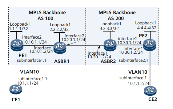
as Figure 1 , CE1 and CE2 belong to the same VPLS and are connected to the backbone network through PE1 in AS100 and PE2 in AS200 respectively.
When there are a large number of cross domain VPLS in each AS, you can configure cross domain BGP VPLS in OptionC mode. In option C cross domain BGP VPLS, VPLS label block information is no longer maintained on ASBR, but VPLS label block information is directly exchanged between PE S.
Figure 1 # configuration of cross domain BGP VPLS networking in OptionC mode
Configuration ideas
-
The IGP protocol is run on the backbone network so that all devices in the same AS domain can communicate with each other.
-
Enable MPLS on the backbone network, establish a dynamic LSP tunnel between PE and ASBR, and enable MPLS on the interface between ASBR.
-
Establish IBGP between PE and ASBR of the same AS.
-
Configure ebgp between ASBRs, and configure routing strategy on ASBR to enable label routing function. Establish MP-EBGP peer relationship between PE1 and PE2.
-
Create a VSI instance between PE1 and PE2 and access CE.
Operation steps
1. Configure the IP address of each device interface
#Configure CE1.
<HUAWEI> system-view
[~HUAWEI] sysname CE1
[*HUAWEI] commit
[~CE1] interface gigabitethernet 1/0/0
[*CE1-GigabitEthernet1/0/0] undo shutdown
[*CE1-GigabitEthernet1/0/0] quit
[*CE1] interface gigabitethernet 1/0/0.1
[*CE1-GigabitEthernet1/0/0.1] ip address 10.1.1.1 24
[*CE1-GigabitEthernet1/0/0.1] quit
[*CE1] commit
#Configure PE1.
<HUAWEI> system-view
[~HUAWEI] sysname PE1
[*HUAWEI] commit
[~PE1] interface loopback1
[*PE1-Loopback1] ip address 1.1.1.1 32
[*PE1-Loopback1] quit
[*PE1] interface gigabitethernet 1/0/0
[*PE1-GigabitEthernet1/0/0] undo shutdown
[*PE1-GigabitEthernet1/0/0] quit
[*PE1] interface gigabitethernet 1/0/0.1
[*PE1-GigabitEthernet1/0/0.1] quit
[*PE1] interface gigabitethernet 2/0/0
[*PE1-GigabitEthernet2/0/0] undo shutdown
[*PE1-GigabitEthernet2/0/0] ip address 10.10.1.1 24
[*PE1-GigabitEthernet2/0/0] quit
[*PE1] commit
#Configure ASBR1.
<HUAWEI> system-view
[~HUAWEI] sysname ASBR1
[*HUAWEI] commit
[~ASBR1] interface loopback1
[*ASBR1-Loopback1] ip address 2.2.2.2 32
[*ASBR1-Loopback1] quit
[*ASBR1] interface gigabitethernet 1/0/0
[*ASBR1-GigabitEthernet1/0/0] undo shutdown
[*ASBR1-GigabitEthernet1/0/0] ip address 10.10.1.2 24
[*ASBR1-GigabitEthernet1/0/0] quit
[*ASBR1] interface gigabitethernet 2/0/0
[*ASBR1-GigabitEthernet2/0/0] undo shutdown
[*ASBR1-GigabitEthernet2/0/0] ip address 10.20.1.1 24
[*ASBR1-GigabitEthernet2/0/0] quit
[*ASBR1] commit
#Configure ASBR2.
<HUAWEI> system-view
[~HUAWEI] sysname ASBR2
[*HUAWEI] commit
[~ASBR2] interface loopback1
[*ASBR2-Loopback1] ip address 3.3.3.3 32
[*ASBR2-Loopback1] quit
[*ASBR2] interface gigabitethernet 1/0/0
[*ASBR2-GigabitEthernet1/0/0] undo shutdown
[*ASBR2-GigabitEthernet1/0/0] ip address 10.20.1.2 24
[*ASBR2-GigabitEthernet1/0/0] quit
[*ASBR2] interface gigabitethernet 2/0/0
[*ASBR2-GigabitEthernet2/0/0] undo shutdown
[*ASBR2-GigabitEthernet2/0/0] ip address 10.30.1.1 24
[*ASBR2-GigabitEthernet2/0/0] quit
[*ASBR2] commit
#Configure PE2.
<HUAWEI> system-view
[~HUAWEI] sysname PE2
[*HUAWEI] commit
[~PE2] interface loopback1
[*PE2-Loopback1] ip address 4.4.4.4 32
[*PE2-Loopback1] quit
[*PE2] interface gigabitethernet 1/0/0
[*PE2-GigabitEthernet1/0/0] undo shutdown
[*PE2-GigabitEthernet1/0/0] ip address 10.30.1.1 24
[*PE2-GigabitEthernet1/0/0] quit
[*PE2] interface gigabitethernet 2/0/0
[*PE2-GigabitEthernet2/0/0] undo shutdown
[*PE2-GigabitEthernet2/0/0] quit
[*PE2] interface gigabitethernet 2/0/0.1
[*PE2-GigabitEthernet2/0/0.1] quit
[*PE2] commit
#Configure CE2.
<HUAWEI> system-view
[~HUAWEI] sysname CE2
[*HUAWEI] commit
[~CE2] interface gigabitethernet 1/0/0
[*CE2-GigabitEthernet1/0/0] undo shutdown
[*CE2-GigabitEthernet1/0/0] quit
[*CE2] interface gigabitethernet 1/0/0.1
[*CE2-GigabitEthernet1/0/0.1] ip address 10.1.1.2 24
[*CE2-GigabitEthernet1/0/0.1] quit
[*CE2] commit
2. Configure the IGP protocol of the backbone network
#Configure PE1.
[~PE1] ospf 1
[*PE1-ospf-1] area 0.0.0.0
[*PE1-ospf-1-area-0.0.0.0] network 1.1.1.1 0.0.0.0
[*PE1-ospf-1-area-0.0.0.0] network 10.10.1.0 0.0.0.255
[*PE1-ospf-1-area-0.0.0.0] quit
[*PE1-ospf-1] quit
[*PE1] commit
#Configure ASBR1.
[~ASBR1] ospf 1
[*ASBR1-ospf-1] area 0.0.0.0
[*ASBR1-ospf-1-area-0.0.0.0] network 2.2.2.2 0.0.0.0
[*ASBR1-ospf-1-area-0.0.0.0] network 10.10.1.0 0.0.0.255
[*ASBR1-ospf-1-area-0.0.0.0] quit
[*ASBR1-ospf-1] quit
[*ASBR1] commit
#Configure ASBR2.
[*ASBR2] ospf 1
[*ASBR2-ospf-1] area 0.0.0.0
[*ASBR2-ospf-1-area-0.0.0.0] network 3.3.3.3 0.0.0.0
[*ASBR2-ospf-1-area-0.0.0.0] network 10.30.1.0 0.0.0.255
[*ASBR2-ospf-1-area-0.0.0.0] quit
[*ASBR2-ospf-1] quit
[*ASBR2] commit
#Configure PE2.
[~PE2] ospf 1
[*PE2-ospf-1] area 0.0.0.0
[*PE2-ospf-1-area-0.0.0.0] network 4.4.4.4 0.0.0.0
[*PE2-ospf-1-area-0.0.0.0] network 10.30.1.0 0.0.0.255
[*PE2-ospf-1-area-0.0.0.0] quit
[*PE2-ospf-1] quit
[*PE2] commit
3. Enable MPLS and establish LSP tunnel
#Configure PE1.
[~PE1] mpls lsr-id 1.1.1.1
[*PE1] mpls
[*PE1-mpls] quit
[*PE1] mpls ldp
[*PE1-mpls-ldp] quit
[*PE1] interface gigabitethernet 2/0/0
[*PE1-GigabitEthernet2/0/0] mpls
[*PE1-GigabitEthernet2/0/0] mpls ldp
[*PE1-GigabitEthernet2/0/0] quit
[*PE1] commit
#Configure ASBR1.
[*ASBR1] mpls lsr-id 2.2.2.2
[*ASBR1] mpls
[*ASBR1-mpls] quit
[*ASBR1] mpls ldp
[*ASBR1-mpls-ldp] quit
[*ASBR1] interface gigabitethernet 1/0/0
[*ASBR1-GigabitEthernet1/0/0] mpls
[*ASBR1-GigabitEthernet1/0/0] mpls ldp
[*ASBR1-GigabitEthernet1/0/0] quit
[*ASBR1] commit
#Configure ASBR2.
[~ASBR2] mpls lsr-id 3.3.3.3
[*ASBR2] mpls
[*ASBR2-mpls] quit
[*ASBR2] mpls ldp
[*ASBR2-mpls-ldp] quit
[*ASBR2] interface gigabitethernet 2/0/0
[*ASBR2-GigabitEthernet2/0/0] mpls
[*ASBR2-GigabitEthernet2/0/0] mpls ldp
[*ASBR2-GigabitEthernet2/0/0] quit
[*ASBR2] commit
#Configure PE2.
[~PE2] mpls lsr-id 4.4.4.4
[*PE2] mpls
[*PE2-mpls] quit
[*PE2] mpls ldp
[*PE2-mpls-ldp] quit
[*PE2] interface gigabitethernet 1/0/0
[*PE2-GigabitEthernet1/0/0] mpls
[*PE2-GigabitEthernet1/0/0] mpls ldp
[*PE2-GigabitEthernet1/0/0] quit
[*PE2] commit
4. Enable MPLS function between domains on ASBR
#Configure ASBR1.
[~ASBR1] interface gigabitethernet 2/0/0
[*ASBR1-GigabitEthernet2/0/0] mpls
[*ASBR1-GigabitEthernet2/0/0-mpls] quit
[*ASBR1] commit
#Configure ASBR2.
[~ASBR2] interface gigabitethernet 1/0/0
[*ASBR2-GigabitEthernet1/0/0] mpls
[*ASBR2-GigabitEthernet1/0/0-mpls] quit
[*ASBR2] commit
5. Configure the IBGP peer between PE1 and ASBR1, PE2 and ASBR2, configure the EBGP peer between ASBR1 and ASBR2, and configure the routing policy on the ASBR. For the routes received from the PE of this AS, allocate the MPLS label when publishing to the opposite ASBR. For the routes published to the PE of this AS, if they are IPv4 routes with labels, the MPLS labels shall be reassigned.
#Configure PE1.
[~PE1] bgp 100
[*PE1-bgp] peer 2.2.2.2 as-number 100
[*PE1-bgp] peer 2.2.2.2 label-route-capability
[*PE1-bgp] peer 2.2.2.2 connect-interface LoopBack 1
[*PE1-bgp] quit
[*PE1] commit
#Configure ASBR1.
[*ASBR1] route-policy policy1 permit node 1
[*ASBR1-route-policy] if-match mpls-label
[*ASBR1-route-policy] apply mpls-label
[*ASBR1-route-policy] quit
[*ASBR1] route-policy policy2 permit node 1
[*ASBR1-route-policy] apply mpls-label
[*ASBR1-route-policy] quit
[*ASBR1] bgp 100
[*ASBR1-bgp] network 1.1.1.1 255.255.255.255
[*ASBR1-bgp] peer 1.1.1.1 as-number 100
[*ASBR1-bgp] peer 1.1.1.1 route-policy policy1 export
[*ASBR1-bgp] peer 1.1.1.1 label-route-capability
[*ASBR1-bgp] peer 1.1.1.1 connect-interface loopback 1
[*ASBR1-bgp] peer 10.20.1.2 as-number 200
[*ASBR1-bgp] peer 10.20.1.2 route-policy policy2 export
[*ASBR1-bgp] peer 10.20.1.2 label-route-capability check-tunnel-reachable
[*ASBR1-bgp] peer 10.20.1.2 connect-interface gigabitethernet 2/0/0
[*ASBR1-bgp]quit
[*ASBR1]commit
#Configure ASBR2.
[*ASBR2] route-policy policy1 permit node 1
[*ASBR2-route-policy] if-match mpls-label
[*ASBR2-route-policy] apply mpls-label
[*ASBR2-route-policy] quit
[*ASBR2] route-policy policy2 permit node 1
[*ASBR2-route-policy] apply mpls-label
[*ASBR2-route-policy] quit
[*ASBR2] bgp 200
[*ASBR2-bgp] network 4.4.4.4 255.255.255.255
[*ASBR2-bgp] peer 4.4.4.4 as-number 200
[*ASBR2-bgp] peer 4.4.4.4 route-policy policy1 export
[*ASBR2-bgp] peer 4.4.4.4 label-route-capability
[*ASBR2-bgp] peer 4.4.4.4 connect-interface loopback 1
[*ASBR2-bgp] peer 10.20.1.1 as-number 100
[*ASBR2-bgp] peer 10.20.1.1 route-policy policy2 export
[*ASBR2-bgp] peer 10.20.1.1 label-route-capability check-tunnel-reachable
[*ASBR2-bgp] peer 10.20.1.1 connect-interface gigabitethernet 1/0/0
[*ASBR2-bgp] quit
[*ASBR2] commit
#Configure PE2.
[~PE2] bgp 200
[*PE2-bgp] peer 3.3.3.3 as-number 200
[*PE2-bgp] peer 3.3.3.3 label-route-capability
[*PE2-bgp] peer 3.3.3.3 connect-interface loopback 1
[*PE2-bgp] quit
[*PE2] commit
After completing this step of configuration and executing the command on ASBR, you can see that the IBGP session state Established between PE and ASBR of the same AS is "Established", and the EBGP session state between ASBR is also "Established". Take the display of ASBR1 AS an example:
[~ASBR1] display bgp peer
 BGP local router ID : 2.2.2.2
 Local AS number : 100
 Total number of peers : 2                 Peers in established state : 2
 Peer            V    AS  MsgRcvd  MsgSent  OutQ  Up/Down       State  PrefRcv
 1.1.1.1         4   100      111      128     0 00:34:24 Established       0
10.20.1.2        4   200       75       89     0 00:38:40 Established       1
Execute the display tunnel info all command on ASBR, and you can find that a tunnel of type "mpls local ifnet" has been created. Take the display of ASBR1 as an example:
[~ASBR1] display tunnel-info all
Tunnel ID                     Type                Destination         Status
-----------------------------------------------------------------------------
0x0000000001004c4b42          ldp                 1.1.1.1             UP
0x000000000c00030000          mpls local ifnet    10.20.1.2           UP
6. Establish MP-EBGP peer between Pe1 and PE2
#Configure PE1.
[~PE1] bgp 100
[*PE1-bgp] peer 4.4.4.4 as-number 200
[*PE1-bgp] peer 4.4.4.4 ebgp-max-hop 255
[*PE1-bgp] peer 4.4.4.4 connect-interface loopback 1
[*PE1-bgp] l2vpn-ad-family
[*PE1-bgp-af-l2vpn-ad] peer 4.4.4.4 enable
[*PE1-bgp-af-l2vpn-ad] peer 4.4.4.4 signaling vpls
[*PE1-bgp-af-l2vpn-ad] quit
[*PE1-bgp] quit
[*PE1] commit
#Configure PE2.
[~PE2] bgp 200
[*PE2-bgp] peer 1.1.1.1 as-number 100
[*PE2-bgp] peer 1.1.1.1 ebgp-max-hop 255
[*PE2-bgp] peer 1.1.1.1 connect-interface loopback 1
[*PE2-bgp] l2vpn-ad-family
[*PE2-bgp-af-l2vpn-ad] peer 1.1.1.1 enable
[*PE2-bgp-af-l2vpn-ad] peer 1.1.1.1 signaling vpls
[*PE2-bgp-af-l2vpn-ad] quit
[*PE2-bgp] quit
[*PE2] commit
After completing this step of configuration, execute the display BGP L2VPN ad peer command on PE1 or PE2, and it can be found that the MP-EBGP peer status between PE1 and PE2 is "Established". Take the display of PE1 as an example:
[~PE1] display bgp l2vpn-ad peer
 BGP local router ID : 1.1.1.1
 Local AS number : 100
 Total number of peers : 1                 Peers in established state : 1
  Peer            V    AS  MsgRcvd  MsgSent  OutQ  Up/Down       State       PrefRcv
  4.4.4.4         4   200       74       66     0 00: 46:06      Established       1
Execute the display tunnel info all command on the PE to find that the cross domain tunnel is successfully established. Take the display of PE1 as an example:
[~PE1] display tunnel-info all
Tunnel ID                     Type                Destination         Status
-----------------------------------------------------------------------------
0x0000000001004c4b42          ldp                 2.2.2.2             UP
0x000000000201040000          bgp                 4.4.4.4             UP
7. Configure VSI instance on PE and access CE
#Configure PE1.
[~PE1] mpls l2vpn
[*PE1-l2vpn] quit
[~PE1] vsi v1 auto
[*PE1-vsi-v1] pwsignal bgp
[*PE1-vsi-v1-bgp] route-distinguisher 100:1
[*PE1-vsi-v1-bgp] vpn-target 1:1 import-extcommunity
[*PE1-vsi-v1-bgp] vpn-target 1:1 export-extcommunity
[*PE1-vsi-v1-bgp] site 1 range 5 default-offset 0
[*PE1-vsi-v1-bgp] quit
[*PE1-vsi-v1] quit
[*PE1] interface gigabitethernet1/0/0.1
[*PE1-GigabitEthernet1/0/0.1] shutdown
[*PE1-GigabitEthernet1/0/0.1] vlan-type dot1q 10
[*PE1-GigabitEthernet1/0/0.1] l2 binding vsi v1
[*PE1-GigabitEthernet1/0/0.1] undo shutdown
[*PE1-GigabitEthernet1/0/0.1] quit
[*PE11] commit
#Configure PE2.
[~PE2] mpls l2vpn
[*PE2-l2vpn] quit
[*PE2] vsi v1 auto
[*PE2-vsi-v1] pwsignal bgp
[*PE2-vsi-v1-bgp] route-distinguisher 200:1
[*PE2-vsi-v1-bgp] vpn-target 1:1 import-extcommunity
[*PE2-vsi-v1-bgp] vpn-target 1:1 export-extcommunity
[*PE2-vsi-v1-bgp] site 2 range 5 default-offset 0
[*PE2-vsi-v1-bgp] quit
[*PE2-vsi-v1] quit
[*PE2] interface gigabitethernet2/0/0.1
[*PE2-GigabitEthernet2/0/0.1] shutdown
[*PE2-GigabitEthernet2/0/0.1] vlan-type dot1q 10
[*PE2-GigabitEthernet2/0/0.1] l2 binding vsi v1
[*PE2-GigabitEthernet2/0/0.1] undo shutdown
[*PE2-GigabitEthernet2/0/0.1] quit
[*PE2] commit
#Configure CE1.
[~CE1] interface gigabitethernet1/0/0.1
[*CE1-GigabitEthernet1/0/0.1] shutdown
[*CE1-GigabitEthernet1/0/0.1] vlan-type dot1q 10
[*CE1-GigabitEthernet1/0/0.1] ip address 10.1.1.1 24
[*CE1-GigabitEthernet1/0/0.1] undo shutdown
[*CE1-GigabitEthernet1/0/0.1] quit
[*CE1] commit
#Configure CE2.
[~CE2] interface gigabitethernet1/0/0.1
[*CE2-GigabitEthernet1/0/0.1] shutdown
[*CE2-GigabitEthernet1/0/0.1] vlan-type dot1q 10
[*CE2-GigabitEthernet1/0/0.1] ip address 10.1.1.2 24
[*CE2-GigabitEthernet1/0/0.1] undo shutdown
[*CE2-GigabitEthernet1/0/0.1] quit
[*CE2] commit
8. Verify the configuration results
View the VSI information on the PE, and you can see that the VSI status is Up. The PW status to the remote PE is also Up. The tunnel used is the previously established cross domain LSP. Take PE1 display as an example:
[~PE1] display vsi name v1 verbose
 ***VSI Name               : v1
    Administrator VSI      : no
    Isolate Spoken         : disable
    VSI Index              : 0
    PW Signaling           : bgp
    Member Discovery Style : auto
    PW MAC Learn Style     : unqualify
    Encapsulation Type     : vlan
    MTU                    : 1500
    Diffserv Mode          : uniform
    Service Class          : --
    Color                  : --
    DomainId               : 255
    Domain Name            :
    Ignore AcState         : disable
    Multicast Fast Swicth  : disable
    Create Time            : 0 days, 0 hours, 27 minutes, 17 seconds
    VSI State              : up
    Resource Status        : Valid

    BGP RD                 : 100:1
    SiteID/Range/Offset    : 1/5/0
    Import vpn target      : 1:1
    Export vpn target      : 1:1

    Remote Label Block     : 25600/5/0
    Local Label Block      : 25600/5/0
    Interface Name         : GigabitEthernet1/0/0.1
    State                  : up
    Last Up Time           : 2014/05/17 10:29:49
    Total Up Time          : 0 days, 0 hours, 26 minutes, 27 seconds

   **PW Information:

   *Peer Ip Address        : 4.4.4.4
    PW State               : up
    Local VC Label         : 25602
    Remote VC Label        : 25601
    PW Type                : label
    Tunnel ID              : 0x6002024
    Broadcast Tunnel ID    : 0x6002024
    Ckey                   : 0x6
    Nkey                   : 0x5
    Main PW Token          : 0x6002024
    Slave PW Token         : 0x0
    Tnl Type               : BGP
    OutInterface           : 1POS2/0/0
    Stp Enable             : 0
    Mac Flapping           : 0
    PW Last Up Time        : 2014/05/17 10:31:05
    PW Total Up Time       : 0 days, 0 hours, 25 minutes, 32 seconds
Execute the display vpls connection bgp verbose command on PE1 to view the BGP VPLS connection. You can find that the connection status is Up.
[~PE1] display vpls connection bgp verbose
VSI Name: v1                               Signaling: bgp
  **Remote Site ID     : 2
    VC State           : up
    RD                 : 200:1
    Encapsulation      : bgp vpls
    MTU                : 1500
    Peer Ip Address    : 4.4.4.4
    PW Type            : label
    Local VC Label     : 25602
    Remote VC Label    : 25601
    Tunnel Policy      : --
    Tunnel ID          : 0x2002001
    Remote Label Block : 25600/5/0
    Export vpn target  : 1:1
CE1 and CE2 can ping each other.
[~CE1] ping 10.1.1.2
  PING 10.1.1.2: 56  data bytes, press CTRL_C to break
    Reply from 10.1.1.2: bytes=56 Sequence=1 ttl=255 time=90 ms
    Reply from 10.1.1.2: bytes=56 Sequence=2 ttl=255 time=77 ms
    Reply from 10.1.1.2: bytes=56 Sequence=3 ttl=255 time=34 ms
    Reply from 10.1.1.2: bytes=56 Sequence=4 ttl=255 time=46 ms
    Reply from 10.1.1.2: bytes=56 Sequence=5 ttl=255 time=94 ms
  --- 10.1.1.2 ping statistics ---
    5 packet(s) transmitted
    5 packet(s) received
    0.00% packet loss
    round-trip min/avg/max = 34/68/94 ms