Daily. Chat
The first column on Zero Foundation Field Program was created on February 2, 2021. It has been a year and only four updates have been made so far. Always say to update, but always drag more, until these two days of friends concerned about it, it comes to mind, here to say sorry to friends who care about you.
In the new year, I will have plenty of time. I will spend more time on this column, keeping my mind the same, or making progress with you, Hey.
Recently, I will be in touch with some home-made field bus development, such as Beijing Weiqili Fuxi software, etc. If you are interested, you can also communicate with us.

Preface
In the Zero Foundation GA series, I did not write the combinatorial logic circuit design, but went directly into the sequential logic circuit design. Since combinatorial logic is relatively simple, let me just mention it here.
Incidentally, I'll move on to the next article about Verilog syntax such as non-blocking assignment, blocking assignment, assign, and always.
1. Understanding Logical Design
Digital circuits can be divided into combinational and sequential logic circuits according to their different functions. The logical features of a combinatorial logic circuit are that the output at any time only depends on the input at that time, and is independent of the original state of the circuit. From the point of view of circuit characteristics, sequential logic is characterized by that the output at any time depends not only on the input at that time, but also on the original state of the circuit. The assign statement is usually the main one. In the circuit structure, combinatorial logic circuits do not involve the processing of signal jump edges, there is no memory circuit, and there is no feedback circuit, which can usually be expressed in the form of a true value table. Sequential logic circuits are structured such that no matter how the input changes, it is only possible for the output to change when the clock reaches along (up or down). Usually the always statement is the main one.
For combinatorial logic, here is a 3-8 decoder circuit:
A decoder is a composite logic circuit with multiple inputs and multiple outputs that translates binary code into specific objects (such as logical electrical equality) and functions opposite to the encoder. Decoders are generally divided into two categories: universal decoders and digital display decoders.
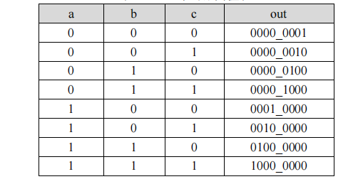
For example, a 38 decoder translates three input states into eight output states, and its true value table is shown below. A, B, C are data inputs and Out are data outputs. In MCU applications, if a certain speed is needed to achieve this function, a single chip, such as 74HC38 or 74LS38, is usually selected to hang out. However, the GA provides a complete imagination and implementation space, and the design requirements can be achieved by itself.
The true value table of the decoder
module decoder(
		a,
		b,
		c,
		out
	);

	input a;//Input Port A
	input b;//Input Port B
	input c;//Input Port C

	output [7:0]out;//Output port
	reg [7:0]out;

	always@(a,b,c)//always@() is a list of sensitive signals in parentheses
	//The always statement can have or without a clock. When always do not have a clock, the logic functions and assign s are exactly the same, producing only combinatorial logic.
	begin
		case({a,b,c})//Judges a,b,c status values, can be tested with dial switch
			3'b000:out = 8'b0000_0001;
			3'b001:out = 8'b0000_0010;
			3'b010:out = 8'b0000_0100;
			3'b011:out = 8'b0000_1000;
			3'b100:out = 8'b0001_0000;
			3'b101:out = 8'b0010_0000;
			3'b110:out = 8'b0100_0000;
			3'b111:out = 8'b1000_0000;
		endcase
	end

endmodule
2. Design of Sequential Logic Circuits
A sequential logic circuit means that the steady state output of a circuit at any time depends not only on the current input, but also on the state formed by the previous input. This is the opposite of combinatorial logic, where the output of the combinatorial logic only has a functional relationship with the current input. In other words, temporal logic has storage elements to store information, while combinatorial logic does not.
A key:
There are many kinds of sequential logic circuits. Here I will talk about the most common counters and compare them with combinational logic circuits. A counter is designed here to flip the LED status on the development board every 500ms. Most development boards on the market have 50MHz crystal oscillation, which means the clock cycle is 20ns (1_500_000), so that 500ms = 500_can be calculated. 000_ 000ns/20ns = 25_ 000_ 000, that is, counter count 25_is required 000_ 000 times, which means you need a counter with at least 25 bits (225>25_000_000>224). And every time the number of counts is reached, it needs to be cleared and counted again.
Verilog HDL is called Hardware Circuit Description Language because we are not programming like C, but writing an actual hardware circuit. Below you will design a counter to control an LED flash.
module counter
(
input clk, //Clock signal 50Mhz
input reset_n,//Reset signal
output led
);

reg led;

parameter MCNT = 24_999_999;

reg [24:0]period_cnt ;	//Define counter registers

//Counter Counting Process
always@(posedge clk or posedge reset_n)
if(reset_n)
	period_cnt <= 25'd0;
else if(period_cnt == MCNT)
	period_cnt <= 25'd0;
else
	period_cnt <= period_cnt + 1'b1;

//led output control process
always@(posedge clk or posedge reset_n)
if(reset_n)
	led <= 1'b1;
else if(period_cnt == MCNT)
	led <= ~led;
else
	led <= led;

endmodule
Because the counter starts at 0 and does not count at 1, it counts to 25'd24_ 999_ Zero at 999 instead of counting to 25'd25_ 000_ 0.000, where the maximum counter value is parameterized. The advantage of parameterized definition is to modify the top-level parameter parameter to complete the modification of the overall variable parameter.
When the counter counts to the preset value, invert the led once to achieve the purpose of flipping.
On the basis of this experiment, breathing lamp experiments can be done with PWM.
3. Expansion: Respiratory Light Experiment
The breathing lamp uses PWM to control the change of LED light brightness by adjusting the duty cycle at a fixed frequency. PWM, Pulse Width Modulation, LEDs do not light up if the duty cycle is 0 for a fixed period of PWM signal generated by a counter. If the duty cycle is 100%, the LED lights are the brightest. Therefore, the "breathing" effect of LED lamp can be achieved by changing the duty cycle from 0 to 100% and then from 100% to 0. The PWM duty cycle adjustment diagram is as follows:
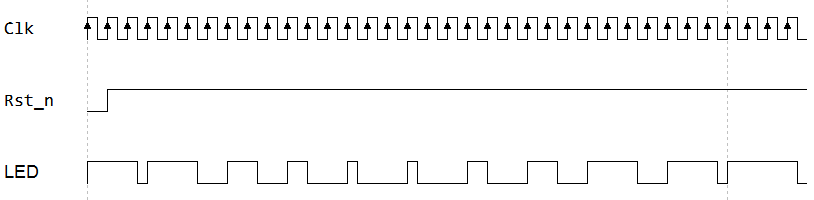
As you can see from the picture above, the time of high level LED decreases from long to short and then from short to long. If the LED light is on at high level, the LED light will show the process of brightness from light to dark and then from dark to light.
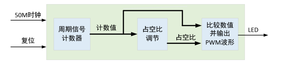
The cycle signal counter is used to generate the pulse signal that drives the LED. In this experiment, the cycle signal frequency is 1Khz, and the duty cycle is increased or decreased by the later logic after each cycle. Finally, the current count value is compared with the duty cycle count value to output the pulse signal with adjustable duty cycle.
module breath_led(
    input   clk   ,  //Clock signal 50Mhz
    input   reset_n ,  //Reset signal

    output  led          //LED
);

//reg define
reg  [15:0]  period_cnt ;   //Cycle counter frequency: 1khz cycle: 1ms count value: 1ms/20ns=50000
reg  [15:0]  duty_cycle ;   //Duty Cycle Value
reg          inc_dec_flag ; //0 Increase 1 Decrease

//Output LED based on size relationship between duty cycle and count value
assign   led = (period_cnt >= duty_cycle) ?  1'b1  :  1'b0;

//Cycle Counter
always @(posedge clk or negedge reset_n) begin
    if(!reset_n)
        period_cnt <= 16'd0;
    else if(period_cnt == 16'd50000)
        period_cnt <= 16'd0;
    else
        period_cnt <= period_cnt + 1'b1;
end

//Increasing or decreasing duty cycles at the beat of a cycle counter
always @(posedge clk or negedge reset_n) begin
    if(!reset_n) begin
        duty_cycle   <= 16'd0;
        inc_dec_flag <= 1'b0;
    end
    else begin
        if(period_cnt == 16'd50000) begin    //Full 1ms
            if(inc_dec_flag == 1'b0) begin   //Duty Cycle Incremental State
                if(duty_cycle == 16'd50000)  //If the duty cycle has increased to the maximum
                    inc_dec_flag <= 1'b1;    //Then the duty cycle starts to decrease
                else                         //Otherwise, the duty cycle increases by 25 Units
                    duty_cycle <= duty_cycle + 16'd25;
            end
            else begin                       //Duty Cycle Decreasing State
                if(duty_cycle == 16'd0)      //If the duty cycle has decreased to 0
                    inc_dec_flag <= 1'b0;    //Then the duty cycle starts to increase
                else                         //Otherwise, the duty cycle decreases by 25 Units
                    duty_cycle <= duty_cycle - 16'd25;
            end
        end
    end
end

endmodule
Lines 21-28 are counters for 1KHz periodic signals used to generate 1KHz LED driving signals. The always block in rows 31-52 is the duty ratio setting module. After each cycle of counting, the duty_cycle is incremented/decremented by 25 counts according to the increment/decrement sign. This incremental or decremental value can be used to control the respiratory rate of the respiratory lamp.
If the duty_cycle value has increased to the maximum, the breathing lamp is already at its brightest state and then begins to decrease. Conversely, if the duty cycle count has decreased to the minimum, that is, 0, the breathing lamp is off and then increases. By doing this, the effect of running water lamp is finally achieved. In line 18 of the code, the output level of the LED is determined by comparing the current cycle count value with the duty cycle count value through combinatorial logic. In a cycle, if the current cycle count value is less than or equal to the duty cycle count value, the LED outputs a high level, that is, light up; If the current cycle count value is greater than the duty cycle count value, the LED output is low, that is, off.