Objectives of this chapter:
- Simulate the process of loading applications by the operating system, demonstrate the relocation method of segments, and thoroughly understand the segmented memory management mechanism of 8086 processor
- Learn the program execution mechanism of x86 processor procedure call
- Understand how x86 processors access peripheral hardware devices
- Summarize all formats of JMP and CALL instructions
- Learn more about x86 processor instructions, such as in, out, shl, shr, rol, ror, jmp, call, ret, etc
8.1 code list of this chapter
8-1, main boot sector program loader
8-2, loaded application
8.2 structure of user program
8.2.1 assembly address of segments and segments and assembly address within segments
1.SECTION and SEGMENT
- NASM assembly instructions define segments through "SECTION" or "SEGMENT". Once a SEGMENT is defined, the following contents belong to that SEGMENT, unless there is another SEGMENT definition
SECTION Segment name
 perhaps
SEGMENT Segment name
-
"align =" clause
used to specify the assembly alignment of a SECTION
align=16 ", indicating that the segment is 16 byte aligned, that is, the physical address can be divided by 16 -
"section. Segment name. start" clause
the assembly address of the segment header relative to the beginning of the whole program is section header. start -
'vstart' clause
although a segment is defined, when a label is referenced, the assembly address at the label is still calculated from the beginning of the whole program, not from the beginning of the segment
8.2.2 user program header
- Loader and user program are developed by different individuals, so "program header" needs to be used for negotiation
- Program header composition
1) length of user program, size in bytes
2) entry point of the application, including segment address and offset address. This is because the application has more than one code snippet
relocation table of section 3). The segment address of each segment is stored and handed over to the loader for relocation. Because the label of assembly code is assembly address, it needs to be converted to memory logical address through relocation table
8.3 work flow of loader
8.3.1 initialization and determination of loading position
The loader needs to decide two things
- See where the memory is free, that is, from which physical memory to start loading user programs
- Where is the user program located on the hard disk and what is its starting logical sector number
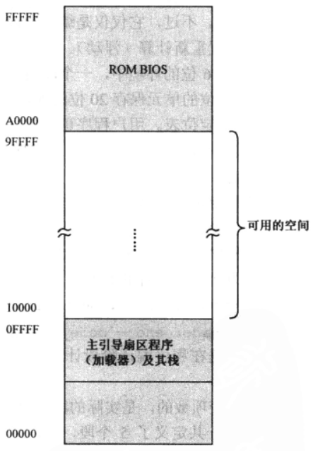
- At first, we directly define an available physical memory address 0x10000, and the memory space is planned as follows
1. equ pseudo instruction
equ pseudo instruction is used to declare a constant, which means "equal to".
Unlike db, dw and dd, values declared with equ do not occupy any assembly address or any memory location at runtime.
8.3.2 prepare to load user program
Interpret lines 12 to 21 of 8-1 code
8.3.3 peripheral equipment and its interface
The communication between processor and peripheral equipment needs to solve two problems
- It is impossible that all I/O interfaces are connected to the processor - bus
- How to solve the conflict between various I/O interfaces ----- use the I/O Controller Hub (ICH), which is the so-called South Bridge on the personal computer
8.3.4 I/O ports and port access
- The processor deals with peripherals through ports. In essence, ports are registers, which are similar to those in the processor. The difference is that PORT registers are located in the I/O interface circuit.
For example:
Hard disk attached PATA/SATA How many ports does the interface have
 Command port: when writing 0 to this port x20 When, it indicates that the data is read from the hard disk; Write 0 x30 Indicates that data is written to the hard disk.
Status port: the processor judges whether the hard disk works normally, whether the operation is successful, and what kind of error has occurred according to the data of this port
 Parameter ports: through these ports, the processor tells the hard disk the number of sectors to read and write and the starting logical sector number
 Data port: continuously take out the data to be read through this port, or continuously send the hard disk data to be written through this interface
 The port data width can be 8 bits, 16 bits, or 32 bits.
PATA/SATA The width of the interface is 16 bits
- Ports have different implementation methods in different computer systems
1) The port is mapped to a memory space address. For example, 0x00xE0000 is the real physical memory address, while 0xE00010xFFFFF is mapped from many I/O interfaces. When accessing this part of address, you are actually accessing the I/O address
2) The port is compiled independently and does not have a relationship with memory. The special pin "M/IO #" makes the access memory and I/O interface mutually exclusive. In Intel system, only 65536 ports are allowed, and the port number ranges from 0x0000 to 0xFFFF. Use in and out instructions to access the port.
1. in instruction, read from port
General form
in al, dx
in ax, dx
in ax, 0xf0      ;From 0 xf0 Read data from the port and put it into the register ax in
- The destination operand of the in instruction must be register AL or AX
- The source operand of the in instruction must be a register dx or an immediate
- The in instruction does not allow the use of other general-purpose registers and memory units
2. out instruction, write to port
The out instruction is opposite to the in instruction
out 0x37, al      ;take al Data write 0 x37 Port number (this is an 8-bit port)
out 0xf5, ax      ;Write 0 xf5 Port number (this is a 16 bit port)
out dx, al      ;This is an 8-bit port with the port number in the register DX in
out dx, ax      ;This is a 16 bit port with the port number in the register DX in
- The destination operand of the out instruction can be an 8-bit immediate or register DX
- The source operand of the out instruction must be register AL or AX
8.3.5 read sector data through hard disk control port
The basic unit of hard disk reading and writing is sector, 512 bytes. In this way, the data exchange between the host and the hard disk is block, so the hard disk is a block device.
How to read and write data from hard disk:
First, send the head number, cylinder number and sector number to the hard disk controller respectively, which is called CHS mode
Second, all sectors are numbered uniformly, that is, the logical sector code. Read and write data according to the logical sector number. This involves the problem of how to number the logical sector? LBA28 and LBA48 are numbered with 28bit and 48bit. 28bit supports 128G at most, which is not enough for the 1T hard disk, so LBA48 is launched
Five steps to read data from hard disk (LBA28 as an example)
- Sets the number of sectors to read
mov dx, 0x1f2      ;Write 0 x1f2 Port, which is an 8-bit port, means that you can only read 256 sectors at a time
mov al, 0x01      ;One sector
out dx, al
- Set the starting LBA sector number
The reading and writing of sectors are continuous, so only the number of the first sector needs to be given.
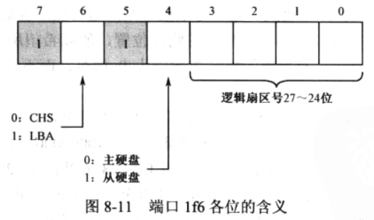
The 28 bit sector number divides it into four segments and writes them into ports 0x1f3, 0x1f4, 0x1f5 and 0x1f6 respectively
mov dx, 0x1f3
mov al, 0x02
out dx, al         ;LBA Address 7~0

inc dx           ;0x1f4
mov al, 0
out dx, al         ;LBA Address 15~8

inc dx           ;0x1f5
out dx, al         ;LBA Address 23~16

inc dx           ;0x1f6
mov al, 0xe0
out dx, al         ;LBA Mode, main hard disk, and LBA Address 27~24
Note the last three lines of the code. Under the current system, each PATA/SATA interface allows two hard disks to be attached, namely Master and Slave.
- Write 0x20 to port 0x1f and request the hard disk to read. This is also an 8-bit port
mov dx, 0x1f7
mov al, 0x20         ;Read command
out dx, al
- Wait for the read-write operation to complete
    mov dx, 0x1f7
.waits:
    in al, dx
    and al, 0x88
    cmp al, 0x08
    jnz .waits         ;Not busy, and the hard disk is ready to transfer data
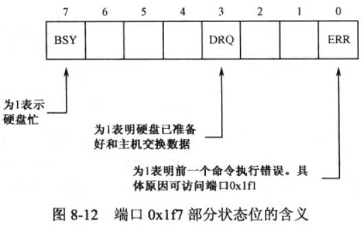
Port 0x1f7 is both a command port and a status port. After sending read-write commands through this port, the hard disk is busy. As shown in Figure 8-12, during its internal operation, it will "1" in position 7 of 0x1f7 port, indicating that it is busy. Once the hard disk is ready, it will clear this bit, indicating that it is busy. At the same time, it will "1" in position 3, which means that it is ready to request the host to send or receive data.
- Continuous extraction of data
0x1f0 is the data port of the hard disk interface, and it is also a 16 bit port.
;The hard disk reads a sector (512 bytes or 256 bytes), and the read data is stored in the segment register DS The offset address of the specified data segment is determined by the register BX appoint
    mov cx, 256
    mov dx, 0x1f0
.readw:
    in ax, dx
    mov [bx], ax
    add bx, 2
    loop .readw
Finally, 0x1f1 port is the error register, which contains the status of the hard disk drive after the last command execution (error reason)
8.3.6 procedure call
The 8-1 code goes to lines 79 to 148
call instruction
The 8086 processor supports four call modes
- 16 bit relatively close call
Near call means that the called target process is located in the current code segment, not another different code segment, so you only need to get the offset address. The relatively near call is a three byte instruction with the opcode 0xE8 followed by a 16 bit operand.
call near proc_1
;keyword near It's not necessary
;Compilation phase: proc_1 Assembly address - call Instruction assembly address - 3 = Operand of machine code
;Execution phase: Register IP Current content + Machine code operand + 3 = Address to be executed next
- 16 bit absolute near call
The operand in the instruction is not the offset, but the real offset address of the called process, so it is called the absolute address. Opcode bit 0xFF
call cx         ;The destination address is cx In, omitted near
call [0x3000]     ;You need to access memory before you can get the target address
call [bx]        ;You need to access memory before you can get the target address
call [bx+si+0x02]   ;You need to access memory before you can get the target address
- 16 bit direct absolute remote call
This call belongs to inter segment call, which is called far call
call 0x2000:0x0030
;The machine code compiled by the instruction is 9 A 30 00 00 20,0x9A The address is followed by the address and the offset code, respectively
- 16 bit indirect absolute remote call
It belongs to inter segment call. The 16 bits here are also used to limit the offset address.
call far [0x2000]
call far [proc_1]
call far [bx]
call far [bx+si]
;Indirect calls must use keywords far
;The above code means to take two words from the specified memory address as the jump offset address and segment address
ret and retf instructions
- ret is a turn back instruction. When it is executed, the processor only does one thing, that is, pop a word from the stack to the instruction pointer register IP
- retf returns the instruction remotely. When it is executed, the processor pops two words from the stack to the instruction pointer register IP and code register CS respectively
8.3.7 loading user program
Interpret 30 ~ 53 lines of code. The function of this code is to load the contents of the sector to the beginning of the memory space 0x10000
8.3.8 relocation of user program
After the contents of the user program are loaded into the memory, the address of the user program in the memory is determined, but what is saved in the relocatable table is still the assembly address, which needs to be converted into a physical address. This is the role of relocatability.
The function of 55 ~ 74 lines of code is to rewrite the relocatable table.
1. adc instruction
adc is a carry addition, which adds the destination operand and the source operand, and then adds the value of the flag register CF. Can be used to complete 32-bit addition.
2. shr and shl instructions
shr(Shift logical Right) logical right instruction. When the logical right shift instruction is executed, the operand will be continuously moved to the right for a specified number of times. Each time it is moved, the "squeezed" bit will be moved to the CF bit of the flag register, and the empty part on the left will be filled with "0".
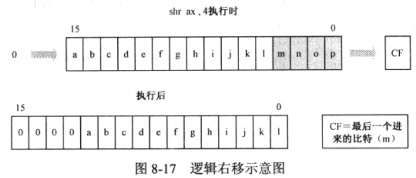
shr ax, 4       ;Register AX Shift the contents of the right by 4 bits.
- Destination operand: 8-bit or 16 bit general-purpose register or memory unit
- Source operand: digit 1, 8-bit immediate, register CL
- format
shr r/m8, 1
shr r/m16, 1
shr r/m8, imm8
shr r/m16, imm8
shr r/m8, cl
shr r/m16, cl
- The shl instruction is a paired instruction of the shr instruction, indicating a shift left
3. ror and rol instructions
ror(ROtate Right) is a rotate right instruction. When the circular shift right instruction is executed, every time it shifts to the right, the shifted bits are sent to both the CF bit of the flag register and the left empty bit.

- The pairing instruction of ror is the circular left shift instruction rol(ROtate Left). The instruction formats of ror, rol, shr and shl are the same.
8.3.9 procedures for handing over control to users
Processor execution
jmp far [0x04]
Start executing user's code
8.3.10 unconditional branch instruction of 8086 processor
- Relatively short transfer
For intra segment branch instructions, the keyword "short" must be used, and the operand is the offset relative to the target position
Operation code: 0xEB
Operand: 1 byte, signed
jmp short infinite
jmp short 0x2000
- 16 bit relative near transfer
Intra segment branch instruction, using the keyword "near", and the operand is the offset relative to the target position
Operation code: 0xE9
Operand: 16 bits (2 bytes), signed
jmp near infinite
jmp near 0x3000
- 16 bit indirect absolute near transfer
For intra segment transfer instructions, the keyword "near" can be omitted
Operand: 16 bit general register or memory address
jump_dest dw 0xc000
jmp [jump_dest]
jmp near cx
- 16 bit direct absolute far transfer
Operation code: 0xEA
jmp 0x0000:0x7c00
;The compiled machine instructions are EA 00 7C 00 00
;The word is stored in the low-end byte order, and after compilation, the offset address is in the front and the segment address is in the back
- 16 bit indirect absolute far transfer (jmp far)
The target address of remote transfer can be obtained indirectly by accessing memory. This is called indirect remote transfer, but the keyword "far" should be used“
jump_far dw 0x33c0, 0xf000
jmp far [jump_far]
;keyword far The function of is to tell the compiler that the instruction should be compiled into a far transfer. After the processor executes this instruction, it accesses the segment register DS For the data segment pointed to, take two words from the offset address given in the instruction to replace the segment register respectively CS Instruction pointer register IP Content of the.

jmp far [bx]
jmp far [bx + si]
8.4 workflow of user program
8.4.1 initialization segment register and stack switching
137 ~ 142 lines of code are explained
1. resb pseudo instruction
It means that the specified number of bytes are reserved from the current position, but their values are not initialized, that is, the value of each byte is uncertain.
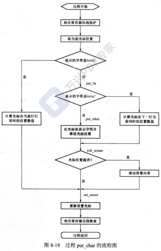
8.4.2 calling string display routine
Lines 171 to 191 are explained
- Carriage Return: push the coordinates to the far left of a line, that is, the beginning of a line.
- Line Feed: push coordinates to the next line.
- Carriage return and line feed (CRLF): both carriage return and line feed, that is, the coordinates will be at the beginning of the next line.
- ASCII code of carriage return: 0x0d.
- ASCII code of newline: 0x0a.
8.4.3 nesting of processes
- Allows another procedure to be invoked in one process, which is called procedure nesting.
- Explained put_ Workflow of string: loop to get a single character from DS: BX and judge whether it is 0. If it is not 0, call another process put_char, 0 returns the main program.
8.4.4 screen cursor control
- Cursor control
The position of the cursor on the screen is saved in two cursor registers inside the graphics card. Each register is 8 bits, which together form a 16 bit value.
For example: 0 indicates that the cursor is in row 0 and column 0 on the screen.
8.4.5 take the current cursor position
Many registers in the graphics card can only be accessed indirectly through the index register.
The port number of the index register is 0x3d4, and a value can be written to it to specify an internal register. For example, the index values of two 8-bit cursor registers are 14 (0x0e) and 15 (0x0f) respectively, which are used to provide the high 8 bits and low 8 bits of the cursor position respectively.
After the register is specified, it should be read and written through the data port 0x3d5.