First of all, let's talk about the process of writing code (take this as an example and don't repeat it):
Whether it is a provincial or national competition, I will find that the nixie tube display and matrix keys are essential, so my first step is to restore the content of the dynamic nixie tube, and let the nixie tube display the content I want to display by assigning a value to the org array. After ensuring that this part is correct, restore the matrix key module, change the contents in the org array and change the nixie tube display by pressing the key. If it is the same as expected, proceed to the next step. I'll show you my time to finish this provincial race. I hope it can help you.
| Analyze the problem. Do you need nixie tube and matrix keys | About 2 minutes |
| Let the nixie tube display 1234.5678 | About 20 minutes |
| Change the display content of the nixie tube through the matrix key | About 20 minutes |
| Read the topic and understand the system requirements | About 10 minutes |
| Modify the mode flag for the S4 key | About 2 minutes |
| For the S5 key, modify the time and start the countdown (two bugs appear after writing: 1. Logic error, the time directly changes from 0 to 2 minutes, and there is no display of 1 minute. 2. After modifying the 1 problem, press the matrix key once to identify multiple times, and add delay to reduce the recognition speed) | About 30 minutes (mostly BUG modification) |
| For S9 key, complete the clearing time function | About 2 minutes |
| Complete the LED lights on and off in different modes (a BUG appears after writing: the LED flashes, and the reason is that it interrupts and preempts the use of P2. This problem is easy for me to analyze from the bottom. In fact, many people can't find the reason at all. We must understand the principle and constantly abolish part of the code temporarily to find out. We'll talk about the specific content later) | About 40 minutes (mostly BUG modification) |
| Complete PWM output (LED is also added here, because there is no oscilloscope around, and the phenomenon can be observed) | About 15 minutes |
| For S8, add the temperature module (a BUG appears after writing: the key fails. After analysis, the reading temperature is outside the control of the delay parameter, which slows down the recognition speed of the matrix key. I choose to make the reading temperature within the control of the delay parameter) | About 30 minutes (mostly BUG modification) |
| Review the questions again and detect the modification function (for example, small details such as count=0 make the system more accurate) | About 10 minutes |
Such time is still quite OK. The remaining time is more than 1 hour. No matter how long the objective question time is, we have enough time. The realization of functions one by one, burning and detecting whether there are problems immediately, and this habit can better solve some problems. However, after communicating with the students, many students found that they are used to burning the whole code directly after writing, and then correcting and modifying the code. However, I want to say that many bugs can't be predicted by you. If you write them together and then modify them, unless you are very familiar with many problems or your analytical ability is superior, Otherwise, you will fall into confusion. Personally, I feel that my level is above the middle level. Point to point BUG modification takes up about half of the programming time. For beginners, I think it's best to be down-to-earth step by step.
Now let's go to code programming. After reading the whole, I'll talk about the modification idea of my BUG (the "/ * same * /" after the function means that the content of the previous module is almost the same [here you learn step by step according to the article I wrote by default]. Because you don't read the previous module when writing the system, the parameter names will be different, and the others are almost the same.):
#include "STC15F2K60S2.H"
#include "stdio.h"
#include "onewire.h" / * is the same as the module I wrote, but different from the official module*/
typedef unsigned int u16;
typedef unsigned char u8;
u8 org[10],tran[9],wei,old,new,mode=1,time,dis,led,delay,flag,count1,low,high,*low1,*high1;
u16 count,te;/*Need 16 digit number to use unsigned integer!!!*/
sfr clock = 0x8f;/*Prepare to turn on the PWM output*/
void lighten(u8 led)/*identical*/
{
P0=0XFF;
P2=P2&0X1F|0X80;
P2=P2&0X1F;
P0=~led;
P2=P2&0X1F|0X80;
P2=P2&0X1F;
}
void close()/*identical*/
{
P0=0;
P2=P2&0X1F|0XA0;
P2=P2&0X1F;
P0=0XFF;
P2=P2&0X1F|0X80;
P2=P2&0X1F;
}
void open()/*One more timer 1 is turned on*/
{
EA=1;
ET0=1;
ET1=1;
}
void Timer1Init(void)/*identical*/ //1ms @ 12.000MHz
{
AUXR |= 0x40; //Timer clock 1T mode
TMOD &= 0x0F; //Set timer mode
TL1 = 0x20; //Set timing initial value
TH1 = 0xD1; //Set timing initial value
TF1 = 0; //Clear TF1 flag
TR1 = 1; //Timer 1 starts timing
}
void translate(u8 org[],u8 tran[])/*identical*/
{
u8 j,k,mid0;
for(j=0,k=0;j<8;j++,k++)
{
switch(org[k])
{
case'0':mid0=0xc0;break;
case'1':mid0=0xf9;break;
case'2':mid0=0xa4;break;
case'3':mid0=0xb0;break;
case'4':mid0=0x99;break;
case'5':mid0=0x92;break;
case'6':mid0=0x82;break;
case'7':mid0=0xf8;break;
case'8':mid0=0x80;break;
case'9':mid0=0x90;break;
case'-':mid0=0xbf;break;
case'c':mid0=0xc6;break;
default:mid0=0xff;
}
if(org[k+1]=='.')
{
mid0&=0x7f;
k++;
}
tran[j]=mid0;
}
}
u8 key_translate()/*identical*/
{
u16 key;
u8 key_return;
P34=0;P35=1;P42=1;P44=1;
key=(key<<4)+(P3&0x0f);
P34=1;P35=0;P42=1;P44=1;
key=(key<<4)+(P3&0x0f);
P34=1;P35=1;P42=0;P44=1;
key=(key<<4)+(P3&0x0f);
P34=1;P35=1;P42=1;P44=0;
key=(key<<4)+(P3&0x0f);
switch(~key)
{
case 0x1000:key_return=19;break;
case 0x2000:key_return=18;break;
case 0x4000:key_return=17;break;
case 0x8000:key_return=16;break;
case 0x0100:key_return=15;break;
case 0x0200:key_return=14;break;
case 0x0400:key_return=13;break;
case 0x0800:key_return=12;break;
case 0x0010:key_return=11;break;
case 0x0020:key_return=10;break;
case 0x0040:key_return=9;break;
case 0x0080:key_return=8;break;
case 0x0001:key_return=7;break;
case 0x0002:key_return=6;break;
case 0x0004:key_return=5;break;
case 0x0008:key_return=4;break;
default:key_return=0;
}
return key_return;
}
void Timer0Init(void)/*identical*/ //100 microseconds @ 12.000MHz
{
AUXR |= 0x80; //Timer clock 1T mode
TMOD &= 0xF0; //Set timer mode
TL0 = 0x50; //Set timing initial value
TH0 = 0xFB; //Set timing initial value
TF0 = 0; //Clear TF0 flag
TR0 = 1; //Timer 0 starts timing
}
void keydo()
{
new=key_translate();
if(new!=old&&new!=0)
{
if(new==4)
{
if(++mode==4) mode=1;/*The three modes switch back and forth*/
switch(mode)
{
case 1:flag=2;count1=0;break;/*flag Used to control the duty cycle*/
case 2:flag=3;count1=0;break;
case 3:flag=7;count1=0;break;
}
}
if(new==5)
{
time+=60;/*Adjustment time*/
if(time>=180) time=0;
else if(time>=120) time=120;
else time=60;
count=0;
}
if(new==9) time=0;/*Time return to 0*/
if(new==8) if(++dis==2) dis=0;/*dis Distinguish display content*/
}
old=new;
}
void display(u8 tran[],u8 wei)/*identical*/
{
P0=0xff;
P2=P2&0X1F|0XE0;
P2=P2&0X1F;
P0=1<<wei;
P2=P2&0X1F|0XC0;
P2=P2&0X1F;
P0=tran[wei];
P2=P2&0X1F|0XE0;
P2=P2&0X1F;
}
void disled()/*LED display*/
{
if(time==0) led=0;/*When the time is 0, turn off the light*/
else
switch(mode)/*Turn on the corresponding lamp according to the mode. Be careful to turn off other lights at the same time*/
{
case 1:led=led&0xf8;led=led|0x01;break;
case 2:led=led&0xf8;led=led|0x02;break;
case 3:led=led&0xf8;led=led|0x04;break;
}
}
void main()
{
low1=&low;high1=&high;
clock=clock|0x01;/*Turn on the PWM output, and the system outputs through P34, that is, timer 0, page 488 of the user's manual*/
close();
rd_temperature(low1,high1);
Timer1Init();
Timer0Init();
open();
while(1)
{
disled();
translate(org,tran);
if(time) lighten(led);
if(!delay)
{
keydo();
rd_temperature(low1,high1);
delay=1;
}
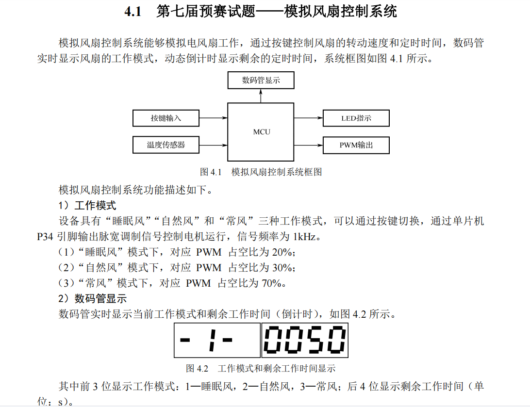
if(dis==0) sprintf(org,"-%1u- %4u",(u16)mode,(u16)time);
if(dis==1)
{
te=(low+high*256);
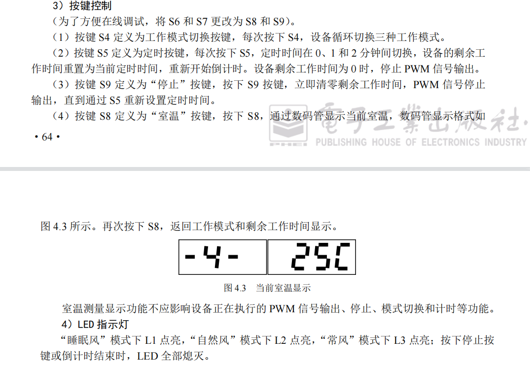
sprintf(org,"-4- %2uc",(u16)(te/16.0));
}
}
}
void time0() interrupt 1
{
if(++wei==8) wei=0;
display(tran,wei);
if(time!=0) lighten(led);
else lighten(0);
if(++count1==10) count1=0;
if(time!=0&&count1<=flag)/*1KHZ The signal cycle is 1 millisecond. Taking natural wind as an example, it needs 300 microseconds high level and 700 microseconds low level. After analyzing all modes, it is decided to program with 100 microseconds as the basic unit*/
{
P34=1;
led=led|0x80;
}
else
{
P34=0;
led=led&0x7f;
}
}
void time1() interrupt 3
{
if(++delay==10) delay=0;
count++;
if(count==1000)
{
count=0;
if(time>0) time--;/*count down*/
}
}In order to facilitate the understanding of the code, I make the meaning of parameters into a table again:
| mode | The initial value is 1, which records the system working mode |
| time | The remaining working time of the system. When it is 0, it means that the system stops working, the PWM output stops, the light is not on, and the countdown stops. Therefore, the function is restricted in many places. |
| dis | Display content to determine whether to display temperature or working state. |
| delay | Slowing down and prolonging the judgment interval can effectively prevent multiple recognition of matrix keys (sometimes, for example, competition and adventure will still affect the output results). |
| flag | Limit the duty cycle of PWM (P34, timer 1) high and low levels in each cycle. |
| count1 | Judge whether the high and low levels need to be changed according to the flag. |
| count | For countdown. |
Finally, I explain the BUG modification process:
Simple bugs don't need to be explained. Errors that can be found by following your own code (that is, logical errors) are not enough to be feared! I choose two explanations.
The table at the beginning of the article mentioned: "for S8, add the temperature module (a BUG appears after writing: the key fails. After analysis, the reading temperature is outside the control of the delay parameter, which slows down the recognition speed of the matrix key. I choose to make the reading temperature within the control of the delay parameter)." How did you find out? When I display the temperature, the matrix key recognition is very slow, but the matrix key is normal when the system working state is displayed, so it must be the problem after pressing S8. In the previous S8, I have a function to identify the temperature, that is, I execute the main function while (1) every time, because when S8 is pressed, I have to read the temperature function, and the temperature module is single line, which is lower than the speed, This causes the execution cycle of keydo to increase instantaneously. I choose to reduce the frequency of executing the read temperature function, which is controlled by delay. Of course, there are many ways. I only choose the one I think of first.
The table at the beginning of the article mentioned: "complete the LED lights on and off in different modes (after writing, there is a BUG: LED flickering. After analysis, the reason is to interrupt and seize the use of P2. This problem is easy to say from the bottom analysis. In fact, many people can't find the reason at all. We must understand the principle and constantly temporarily abolish some codes to find out. We'll talk about the specific content later) "
The latches of nixie tube and led are finally selected through P2, so if one is located in the main function (lighten function) and the other is located in the interrupt (display function), they will interfere with each other. The principle can be seen as follows:
Blue Bridge Cup MCU module code (LED) (code + comment)_ tuygre blog - CSDN blog
There is a complete explanation in the code.
The header file onewire has been modified. See for details Blue Bridge Cup MCU module code (DS18B20 temperature measurement) (code + comment)_ tuygre blog - CSDN blog
In fact, fixing bugs is the difficulty of the game, which requires the ability of independent analysis, and sometimes basic knowledge and understanding of principles. If you can't, practice more! After that, update the provincial competition at least once a week. Hope to pay attention!
The download address of the schematic diagram and user manual officially provided is as follows:
Link: https://pan.baidu.com/s/1y8lRYHxLKojL4_r0PZPYRw
Extraction code: 19so
The notes cannot be inserted into the picture. The relevant information mentioned can be found in the folder by the reader himself.
Nanjing University of information engineering undergraduate study notes for your reference.
If there is any error, contact QQ3182097183.