catalogue
2. kubernetes design architecture
4. kubernetes design structure
2. Install Kubernetes using the deployment tool kubedm
3. Installing flannel network components
4. Other nodes access k8s cluster
1. Creation and deletion of pod
2. Port exposure in pod -- service microservice
2. Pod expansion and shrinkage
2. Parameter details in resource list
1. Pod life cycle structure diagram
2. Official documentation of Pod's life cycle
6. Examples of live and ready probes
1. Basic concept of controller
2. Official documentation of the controller
4. Deployment controller example - version rollback
5. DaemonSet controller example - ensure that a copy of a Pod is running on all (or some) nodes
6. Job controller example -- execute batch tasks, execute tasks only once, and exit after completion
2. Deployment controller + svc service
1. Principle of cross host communication in Flannel vxlan mode
3. flannel supports multiple back ends
4. calico network plug-in (details will be introduced later)
5. Headless Service "Headless Service"
6. The second way to access services from outside is LoadBalancer type services
7. Deploying Metallb-layer2 environment on a stand-alone computer
8. The third way to access a service externally is ExternalName
9. Ingress Service -- accessing the internal cluster from the external network
(1) Deployment steps of basic ingress structure:
(2) Inress deployment extension -- domain name based virtual host
10. Advanced features of ingress
11. Canary publishing practice
(1)calico network plug-in official website
(3)calico network architecture
(5)calico installation and deployment
Experiment 1 - set calico network policy, the contents are as follows:
Experiment 2 - set calico network policy, the contents are as follows:
1, Introduction to Kubernetes
1. Introduction to Kubernetes
With the rapid development of Docker as an advanced container engine, container technology has been applied in Google for many years, and Borg system runs and manages thousands of container applications.
Kubernetes project originates from Borg, which can be said to be the essence of Borg design thought, and has absorbed the experience and lessons of Borg system.
Kubernetes abstracts computing resources at a higher level, and gives the final application services to users by carefully combining containers.
Kubernetes benefits:
(1) Hide resource management and error handling. Users only need to pay attention to application development.
(2) The service is highly available and reliable.
(3) The load can be run in a cluster composed of thousands of machines.
2. kubernetes design architecture
Kubernetes cluster includes node agent kubelet and Master components (APIs, scheduler, etc.), all based on distributed storage system.
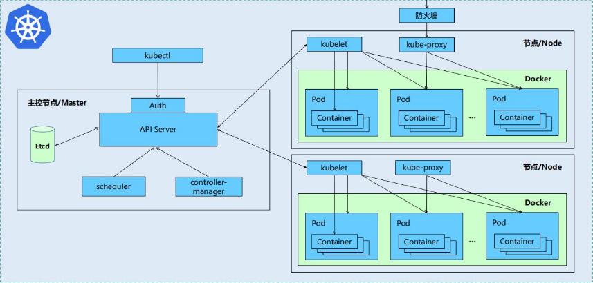
3. Kubernetes core components
Kubernetes is mainly composed of the following core components:
| etcd | The state of the entire cluster is saved |
| apiserver | It provides a unique entry for resource operation, and provides mechanisms such as authentication, authorization, access control, API registration and discovery |
| controller manager | Be responsible for maintaining the status of the cluster, such as fault detection, automatic expansion, rolling update, etc |
| scheduler | Be responsible for resource scheduling, and schedule the Pod to the corresponding machine according to the predetermined scheduling strategy |
| kubelet | Responsible for maintaining the life cycle of the container, as well as the management of Volume (CVI) and network (CNI) |
| Container runtime | Responsible for image management and real operation of Pod and container (CRI) |
| kube-proxy | Responsible for providing Service discovery and load balancing within the cluster for services |
In addition to the core components, there are some recommended add ons:
| kube-dns | Responsible for providing DNS services for the whole cluster |
| Ingress Controller | Provide Internet access for services |
| Heapster | Provide resource monitoring |
| Dashboard | Provide GUI |
| Federation | Provide clusters across availability zones |
| Fluentd-elasticsearch | Provide cluster log collection, storage and query |
4. kubernetes design structure
Kubernetes design concept and function is actually a layered architecture similar to Linux
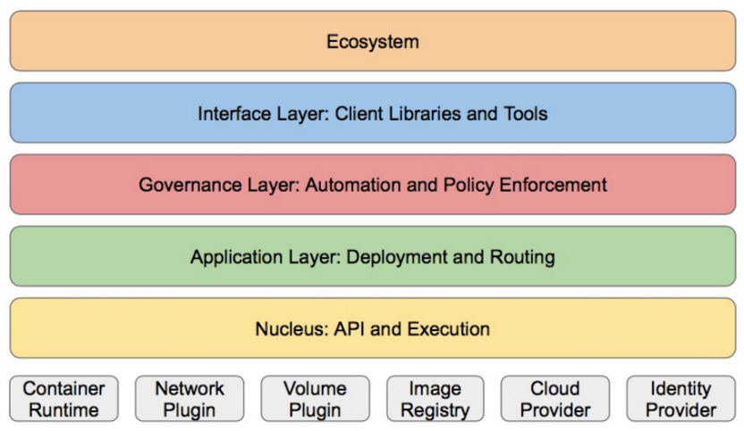
Core layer: the core function of Kubernetes, which provides API s to build high-level applications externally and plug-in application execution environment internally
Application layer: Deployment (stateless applications, stateful applications, batch tasks, cluster applications, etc.) and routing (service discovery, DNS resolution, etc.)
Management: system measurement (such as infrastructure, container and network measurement), automation (such as automatic expansion, dynamic Provision, etc.) and policy management (RBAC, Quota, PSP, NetworkPolicy, etc.)
Interface layer: kubectl command line tool, CLIENT SDK and cluster Federation
Ecosystem: a huge container cluster management and scheduling ecosystem above the interface layer, which can be divided into two categories: Kubernetes external: log, monitoring, configuration management, CI, CD, Workflow, FaaS, OTS application, ChatOps, etc
Kubernetes internal: CRI, CNI, CVI, image warehouse, Cloud Provider, cluster configuration and management, etc
2, Kubernetes deployment
1. Official documents:
Container runtimes | KubernetesYou need to install a container runtime into each node in the cluster so that Pods can run there. This page outlines what is involved and describes related tasks for setting up nodes.Kubernetes 1.23 requires that you use a runtime that conforms with the Container Runtime Interface (CRI).See CRI version support for more information.This page lists details for using several common container runtimes with Kubernetes, on Linux: https://kubernetes.io/docs/setup/production-environment/container-runtimes/#docker Preparation: this experiment takes server1 as the harbor warehouse, deploys k8s on three virtual machines: server2, server3 and server4, and server2 as the management node.
stay server2,server3,server4 Upper reset docker
  300  systemctl status docker
  301  rm -f /etc/systemd/system/docker.service.d/10-machine.conf
  302  systemctl daemon-reload
  303  systemctl restart docker.service
  304  systemctl restart docker.socket
  305  docker info


stay server1 Shangqingkong docker-machine node
[root@server1 harbor]# docker-machine rm server4
About to remove server4
WARNING: This action will delete both local reference and remote instance.
Are you sure? (y/n): y
Successfully removed server4
[root@server1 harbor]# docker-machine ls
NAME   ACTIVE   DRIVER   STATE   URL   SWARM   DOCKER   ERRORS
2. Install Kubernetes using the deployment tool kubedm
#Change the engine file on server2/3/4 and set cgroupdriver=systemd
[root@server2 ~]# cat /etc/docker/daemon.json
{
  "registry-mirrors": ["https://reg.westos.org"],
  "exec-opts": ["native.cgroupdriver=systemd"],
  "log-driver": "json-file",
  "log-opts": {
    "max-size": "100m"
  },
  "storage-driver": "overlay2"
}
[root@server2 ~]# systemctl daemon-reload
[root@server2 ~]# systemctl restart docker


#Disable swap swap partition on server2/3/4
[root@server2 ~]# swapoff -a
[root@server2 ~]# vim /etc/fstab
 11 #/dev/mapper/rhel-swap   swap                    swap    defaults        0 0

#Allow iptables of server2/3/4 to check bridge traffic
[root@server2 ~]# vim /etc/sysctl.d/docker.conf
[root@server2 ~]# cat /etc/sysctl.d/docker.conf
    net.bridge.bridge-nf-call-iptables = 1
    net.bridge.bridge-nf-call-ip6tables = 1
[root@server2 ~]# sysctl --system
Install software: configure the software source and install the software kubedm, kubelet and kubectl
#Configure alicloud software source on server2/3/4 to install kubedm
[root@server2 yum.repos.d]# vim /etc/yum.repos.d/k8s.repo
[root@server2 yum.repos.d]#
[root@server2 yum.repos.d]# cat /etc/yum.repos.d/k8s.repo
[kubernetes]
name=Kubernetes
baseurl=https://mirrors.aliyun.com/kubernetes/yum/repos/kubernetes-el7-x86_64/
enabled=1
gpgcheck=0

#Install the software on server2/3/4 and activate and start kubelet automatically
[root@server2 yum.repos.d]# yum install -y kubeadm kubelet kubectl
[root@server2 yum.repos.d]# systemctl enable --now kubelet
Deploy Kubernetes
kubeadm config print init-defaults //View default configuration information
#Delete all unused images in server1
docker images |grep -v REPOSITORY |awk '{system("docker rmi "$1":"$2"")}'

#Query the image required by kubedm in server2
[root@server2 yum.repos.d]# kubeadm config images list --image-repository registry.aliyuncs.com/google_containers
registry.aliyuncs.com/google_containers/kube-apiserver:v1.23.4
registry.aliyuncs.com/google_containers/kube-controller-manager:v1.23.4
registry.aliyuncs.com/google_containers/kube-scheduler:v1.23.4
registry.aliyuncs.com/google_containers/kube-proxy:v1.23.4
registry.aliyuncs.com/google_containers/pause:3.6
registry.aliyuncs.com/google_containers/etcd:3.5.1-0
registry.aliyuncs.com/google_containers/coredns:v1.8.6

#Pull the required image in server1
 1146  docker pull registry.aliyuncs.com/google_containers/kube-apiserver:v1.23.4
 1147  docker pull registry.aliyuncs.com/google_containers/kube-controller-manager:v1.23.4
 1148  docker pull registry.aliyuncs.com/google_containers/kube-scheduler:v1.23.4
 1149  docker pull registry.aliyuncs.com/google_containers/kube-proxy:v1.23.4
 1150  docker pull  registry.aliyuncs.com/google_containers/pause:3.6
 1151  docker pull registry.aliyuncs.com/google_containers/etcd:3.5.1-0
 1152  docker pull registry.aliyuncs.com/google_containers/coredns:v1.8.6
Modify the image label in server1 and upload it to the harbor private warehouse
#Modify the image label in server1
[root@server1 ~]# docker images | grep aliyuncs | awk '{print $1":"$2}' |awk -F/ '{system("docker tag "$0" reg.westos.org/k8s/"$3"")}'
#After modification, it is as follows:
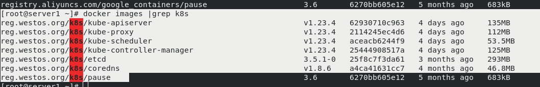
[root@server1 ~]# docker images |grep k8s
reg.westos.org/k8s/kube-apiserver v1.23.4 62930710c963 4 days ago 135MB
reg.westos.org/k8s/kube-proxy v1.23.4 2114245ec4d6 4 days ago 112MB
reg.westos.org/k8s/kube-scheduler v1.23.4 aceacb6244f9 4 days ago 53.5MB
reg.westos.org/k8s/kube-controller-manager v1.23.4 25444908517a 4 days ago 125MB
reg.westos.org/k8s/etcd 3.5.1-0 25f8c7f3da61 3 months ago 293MB
reg.westos.org/k8s/coredns v1.8.6 a4ca41631cc7 4 months ago 46.8MB
reg.westos.org/k8s/pause 3.6 6270bb605e12 5 months ago 683kB
#Upload the image with the label changed to the harbor private warehouse in server1
[root@server1 ~]# docker images |grep k8s | awk '{system("docker push "$1":"$2"")}'
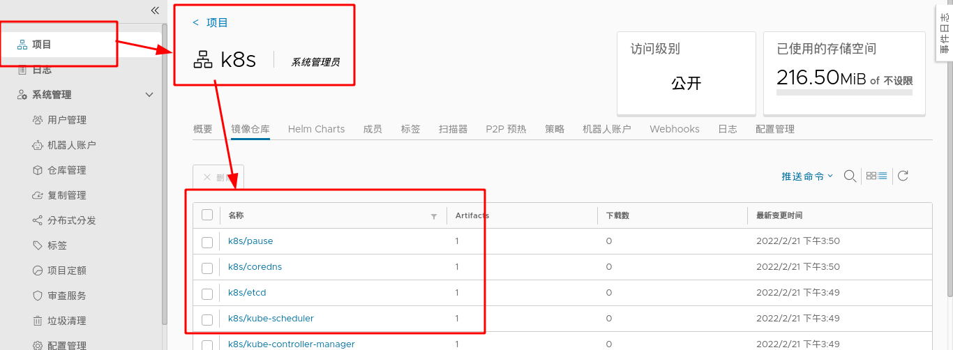
Query the image of the local private harbor warehouse in server2 and start deploying k8s clusters
Note: when a pit is encountered during initialization, at least two CPUs are required; RAM memory shall be at least 2G.
If the initialization fails, you can use the < kubedm reset > command to reset the node.
#Query the image of private harbor warehouse in server2
[root@server2 ~]# kubeadm config images list --image-repository reg.westos.org/k8s

#Pull the image of the private harbor warehouse in server2
[root@server2 ~]# kubeadm config images pull --image-repository reg.westos.org/k8s

#Initialize the cluster in server2
[root@server2 ~]# kubeadm init --pod-network-cidr=10.244.0.0/16 --image-repository reg.westos.org/k8s
#Execute authorization (execute it every time you restart the system, or put it directly into the. bash_profile and start it automatically)
[root@server2 ~]# export KUBECONFIG=/etc/kubernetes/admin.conf
[root@server2 ~]# vim .bash_profile
[root@server2 ~]# cat .bash_profile
    export KUBECONFIG=/etc/kubernetes/admin.conf


#Master view status
[root@server2 ~]# kubectl get pod --all-namespaces
NAMESPACE     NAME                              READY   STATUS    RESTARTS   AGE
kube-system   coredns-7b56f6bc55-6httc          0/1     Pending   0          6m10s
kube-system   coredns-7b56f6bc55-k5fnm          0/1     Pending   0          6m10s
kube-system   etcd-server2                      1/1     Running   0          6m24s
kube-system   kube-apiserver-server2            1/1     Running   0          6m26s
kube-system   kube-controller-manager-server2   1/1     Running   0          6m24s
kube-system   kube-proxy-5rgqp                  1/1     Running   0          6m11s
kube-system   kube-scheduler-server2            1/1     Running   0          6m24s
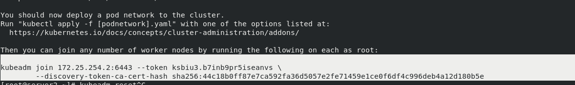
Note: after the initialization of management node server2 is completed, a command will be generated at the end. Other nodes can directly join the k8s cluster by executing this command. The command is as follows:
3. Installing flannel network components
#Download the flannel plug-in on server2
[root@server2 ~]# wget https://raw.githubusercontent.com/coreos/flannel/master/Documentation/kube-flannel.yml

Search from this file“/image"Get two images,stay server1 Pull image from,And upload to harbor Warehouse
#Pull image
 1160  docker pull  rancher/mirrored-flannelcni-flannel-cni-plugin:v1.0.1
 1161  docker pull rancher/mirrored-flannelcni-flannel:v0.16.3
#Change mirror label
 1162  docker tag rancher/mirrored-flannelcni-flannel-cni-plugin:v1.0.1 reg.westos.org/rancher/mirrored-flannelcni-flannel-cni-plugin:v1.0.1
 1163  docker tag rancher/mirrored-flannelcni-flannel:v0.16.3 reg.westos.org/rancher/mirrored-flannelcni-flannel:v0.16.3
#Upload image to harbor
 1164  docker push reg.westos.org/rancher/mirrored-flannelcni-flannel-cni-plugin:v1.0.1
 1165  docker push reg.westos.org/rancher/mirrored-flannelcni-flannel:v0.16.3
Note: you need to create "Ranger" in harbor warehouse in advance

#Installing network components
[root@server2 ~]# kubectl apply -f kube-flannel.yml
(
kubectl apply -f https://raw.githubusercontent.com/coreos/flannel/master/Documentation/kube-flannel.yml) since the previous step has been downloaded from the website, it can be installed directly
4. Other nodes access k8s cluster
After the k8s management node of server2 is initialized, server3 and server4 execute the command to join the node. After joining successfully, you can view the cluster members in server2
#Execute this command in server3/4 to join the k8s cluster managed by server2
[root@server3 ~]# kubeadm join 172.25.254.2:6443 --token ksbiu3.b7inb9pr5iseanvs --discovery-token-ca-cert-hash sha256:44c18b0ff87e7ca592fa36d5057e2fe71459e1ce0f6df4c996deb4a12d180b5e

#View nodes in k8s cluster in server2
[root@server2 ~]# kubectl get node
NAME      STATUS   ROLES                  AGE   VERSION
server2   Ready    control-plane,master   41m   v1.23.4
server3   Ready    <none>                 22s   v1.23.4
server4   Ready    <none>                 35s   v1.23.4
#Check that the status of all containers in the cluster is "running" in server2, which proves that k8s cluster deployment is successful
[root@server2 ~]# kubectl get pod --all-namespaces
NAMESPACE     NAME                              READY   STATUS    RESTARTS   AGE
kube-system   coredns-7b56f6bc55-6httc          1/1     Running   0          47m
kube-system   coredns-7b56f6bc55-k5fnm          1/1     Running   0          47m
kube-system   etcd-server2                      1/1     Running   0          48m
kube-system   kube-apiserver-server2            1/1     Running   0          48m
kube-system   kube-controller-manager-server2   1/1     Running   0          48m
kube-system   kube-flannel-ds-fdwcr             1/1     Running   0          17m
kube-system   kube-flannel-ds-vkrd8             1/1     Running   0          7m1s
kube-system   kube-flannel-ds-wp5x5             1/1     Running   0          6m47s
kube-system   kube-proxy-5pvc7                  1/1     Running   0          7m1s
kube-system   kube-proxy-5rgqp                  1/1     Running   0          47m
kube-system   kube-proxy-lbglv                  1/1     Running   0          6m47s
kube-system   kube-scheduler-server2            1/1     Running   0          48m
When the kubernetes cluster is expanded, the new node can automatically join the cluster by directly executing the above command; However, it should be noted that the valid period of the token in the command is 24 hours. When adding, you need to update the token in the command. Refer to official documents for specific methods:
kubeadm join --token <token> <control-plane-host>:<control-plane-port> --discovery-token-ca-cert-hash sha256:<hash>
< token >: kubedm token list. If it expires, use kubedm token create
<control-plane-host>:<control-plane-port> : cat /etc/kubernetes/admin. You can find it in conf
<hash> : openssl x509 -pubkey -in /etc/kubernetes/pki/ca.crt | openssl rsa -pubin -outform der 2>/dev/null | openssl dgst -sha256 -hex | sed 's/^.* //'
kubectl command Guide:
Kubectl Reference Docs https://kubernetes.io/docs/reference/generated/kubectl/kubectl-commands
Master View status:
kubectl get cs
kubectl get node
kubectl get pod -n kube-system -o wide

see pod Specific information
kubectl get pod -n kube-system -o wide          #Show all pod s
kubectl describe pod kube-proxy-5pvc7 -n kube-system        #Display all information of kube-proxy-5pvc7
kubectl logs kube-proxy-5pvc7 -n kube-system            #Display kube-proxy-5pvc7 log
                    -n:appoint namespace

#View all namespace s
[root@server2 ~]# kubectl get ns
NAME              STATUS   AGE
default           Active   3d4h
kube-node-lease   Active   3d4h
kube-public       Active   3d4h
kube-system       Active   3d4h
#Specify namespace
[root@server2 ~]# kubectl get pod -n kube-system
NAME                              READY   STATUS    RESTARTS      AGE
coredns-7b56f6bc55-6httc          1/1     Running   1 (28m ago)   3d4h
coredns-7b56f6bc55-k5fnm          1/1     Running   1 (28m ago)   3d4h
etcd-server2                      1/1     Running   1 (28m ago)   3d4h
kube-apiserver-server2            1/1     Running   1 (28m ago)   3d4h
kube-controller-manager-server2   1/1     Running   1 (28m ago)   3d4h
kube-flannel-ds-fdwcr             1/1     Running   1 (28m ago)   3d4h
kube-flannel-ds-vkrd8             1/1     Running   1 (28m ago)   3d3h
kube-flannel-ds-wp5x5             1/1     Running   1 (28m ago)   3d3h
3, Pod management
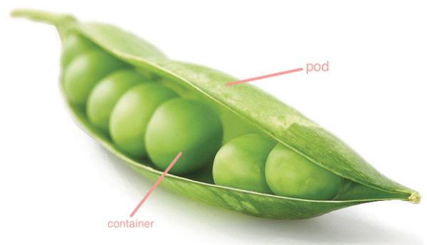
Pod is the smallest deployable unit that can create and manage Kubernetes computing. A pod represents a process running in the cluster, and each pod has a unique ip.
A pod is similar to a pea pod and contains one or more containers (usually docker s). IPC, Network and UTC namespace are shared among multiple containers.
Pod can provide a relatively persistent storage environment. When the container is reset or hung up, the data can be temporarily stored in the pod. As long as there is no problem with the pod, there will be no problem with the data.
1. Creation and deletion of pod
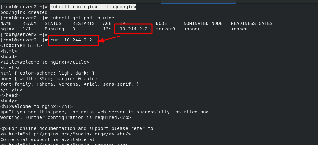
#Create and run pod
kubectl run nginx --image=nginx            #Create and run nginx images in the current namespace
kubectl get pod -o wide                     #View the image information in the current namespace

#Delete pod
kubectl delete pod nginx
Note: when using the "kubectl run" command to create a pod, it is an autonomous pod, which will disappear if deleted; When you create a pod using the "kubectl create deployment" command, a controller is created to manage the pod.
#Create multiple containers in one pod at the same time. The pod name is my Dep
kubectl create deployment my-dep --image=myapp:v1 --replicas=3

#To delete a pod, you need to delete the controller
kubectl delete deployments.apps my-dep             #Delete controller
kubectl delete svc my-dep                         #Delete network
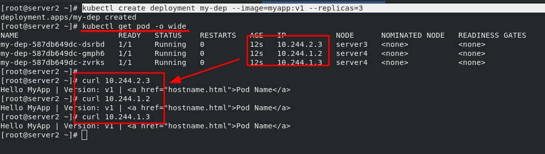
Note: the IP after the creation of pod can only be accessed inside the cluster, but not outside the network. Therefore, it is necessary to expose the pod in the cluster to the outside of the cluster.
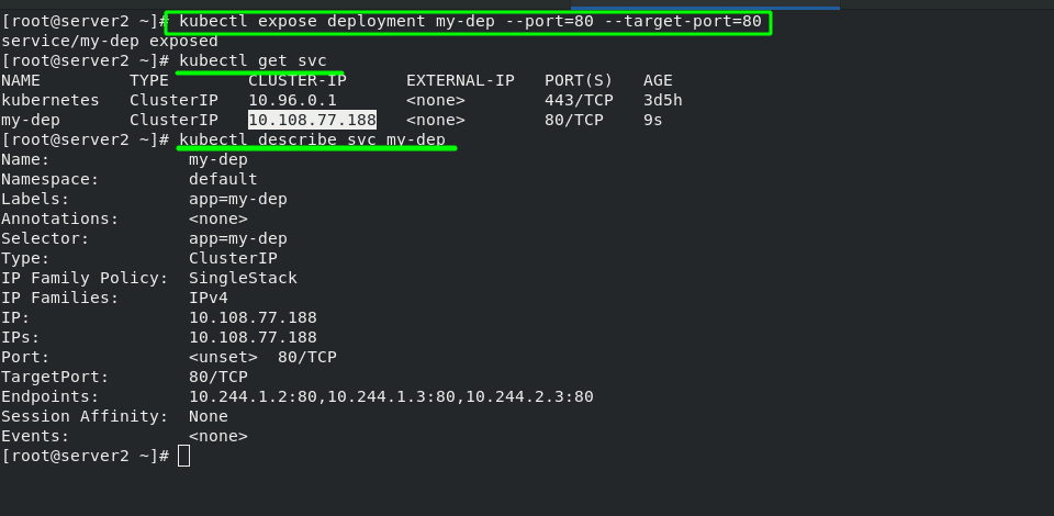
[root@server2 ~]# kubectl expose deployment my-dep --port=80 --target-port=80
service/my-dep exposed
[root@server2 ~]# kubectl get svc
NAME         TYPE        CLUSTER-IP      EXTERNAL-IP   PORT(S)   AGE
kubernetes   ClusterIP   10.96.0.1       <none>        443/TCP   3d5h
my-dep       ClusterIP   10.108.77.188   <none>        80/TCP    9s
2. Port exposure in pod -- service microservice
Service is an abstract concept, which defines the logical collection of multiple pods of a service and the strategy of accessing pod. Generally, service is called micro service.
Create service
$ kubectl expose deployment nginx --port=80 --target-port=80
At this time, the pod client can access the two backend pods through the name of the service
ClusterIP: the default type, which automatically assigns a virtual IP that can only be accessed within the cluster
Use the NodePort type to expose the port and allow external clients to access the Pod
$kubectl edit svc nginx / / modify the type of service to NodePort
$kubectl expose deployment nginx -- port = 80 -- target port = 80 -- type = nodeport / / you can also specify the type when creating a service
NodePort: bind a port on each machine for the Service on the basis of ClusterIP, so that the Service can be accessed through NodeIP:NodePort
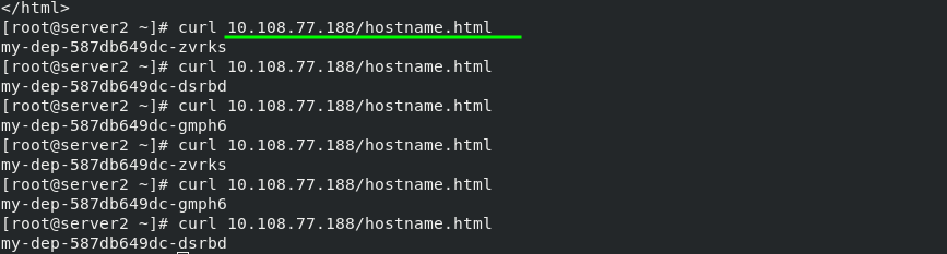
After the port is exposed, an IP will be allocated to the whole pod and accessed in the cluster, which shows load balancing. This load balancing is not realized through lvs, but through iptables. It is randomly distributed!!!
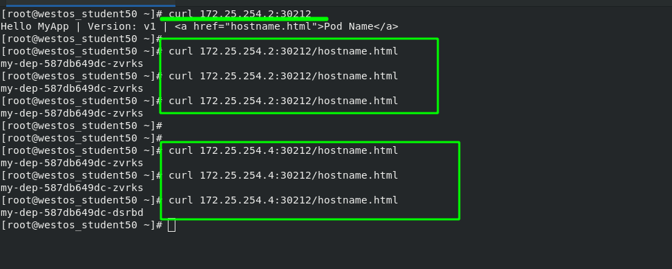
The first way to access the pod from the outside: NodePort
In order to solve the problem of external network accessing cluster nodes, the following configuration is also required:
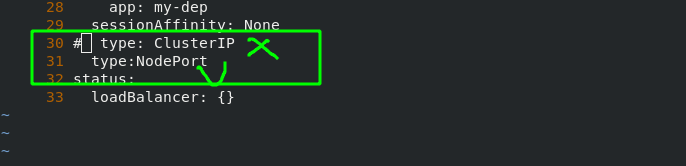
Change "ClusterIP" to "NodePort". After configuration, it is found that a new port "30212" is added to my dep's network, which can be understood as port mapping.
#Display pod network information
[root@server2 ~]# kubectl get svc
NAME         TYPE        CLUSTER-IP      EXTERNAL-IP   PORT(S)   AGE
kubernetes   ClusterIP   10.96.0.1       <none>        443/TCP   3d5h
my-dep       ClusterIP   10.108.77.188   <none>        80/TCP    36m

#Edit the network of my dep pod. The network changes are as follows
[root@server2 ~]# kubectl edit svc my-dep
service/my-dep edited

#Check the network information of pod again
[root@server2 ~]# kubectl get svc
NAME         TYPE        CLUSTER-IP      EXTERNAL-IP   PORT(S)        AGE
kubernetes   ClusterIP   10.96.0.1       <none>        443/TCP        3d5h
my-dep       NodePort    10.108.77.188   <none>        80:30212/TCP   37m
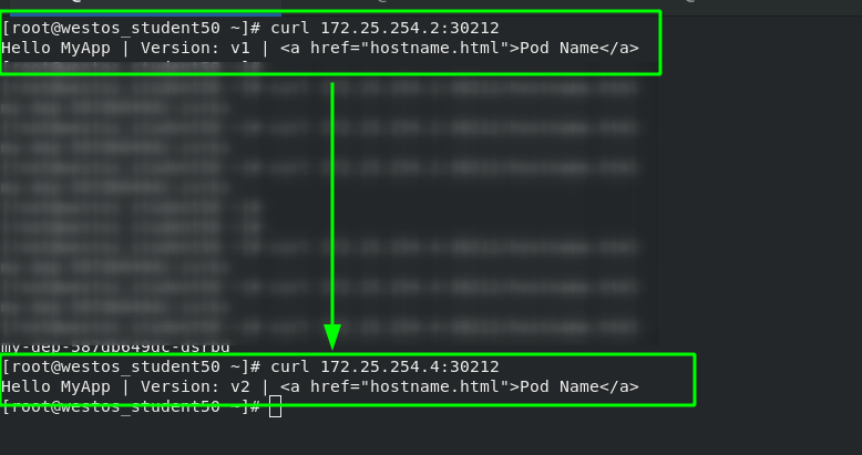
After the configuration is completed, test the external network again, and add the mapped port during the test. You can see that accessing any node in the cluster will get the same result.
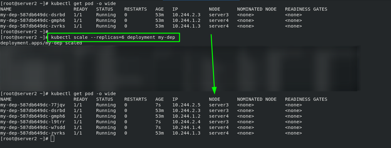
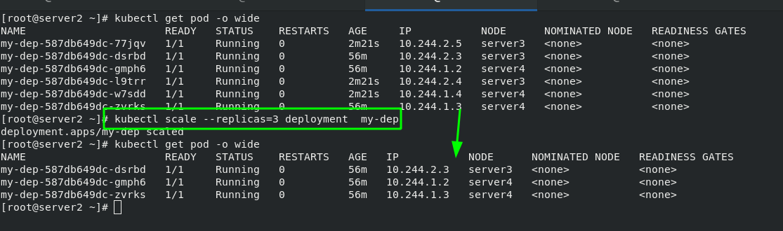
2. Pod expansion and shrinkage
#pod expansion
kubectl scale --replicas=6 deployment my-dep

#pod volume reduction
kubectl scale --replicas=3 deployment  my-dep
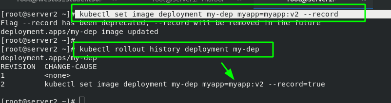
3. Update pod image
#Update the pod image from myapp:v1 to myapp:v2
kubectl set image deployment my-dep myapp=myapp:v2 --record

#View the update history of my dep
kubectl rollout history deployment my-dep
After the master side of server2 is changed, you can see that the version has been updated when accessing the external network
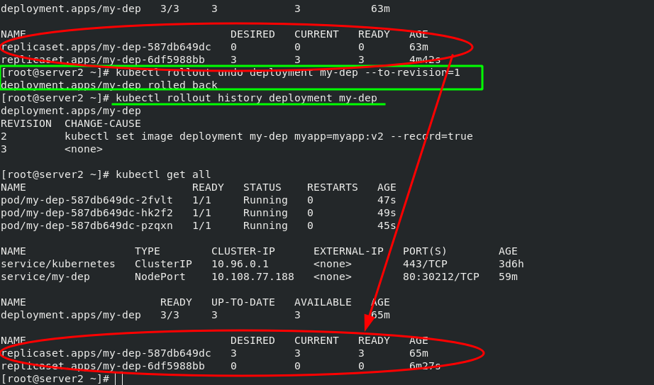
#pod version rollback
kubectl rollout undo deployment my-dep --to-revision=1
After the pod version is rolled back, view the version update history; View the current pod information; Testing; Obvious effects can be seen.
4, Resource list
yaml resource list tutorial
1. Resource list example
#Create and run a pod
[root@server2 ~]# kubectl run demo --image=nginx
pod/demo created

#View status
[root@server2 ~]# kubectl get pod
NAME   READY   STATUS    RESTARTS   AGE
demo   1/1     Running   0          10s

#Output this pod as demo Yaml file
[root@server2 ~]# kubectl get pod -o yaml > demo.yaml

#Create pod from yaml file
[root@server2 pod]# kubectl apply -f demo.yaml
pod/demo created

#Delete pod
[root@server2 pod]# kubectl delete -f demo.yaml
pod "demo" deleted

#View pod information
[root@server2 pod]# kubectl describe pod demo

#Show node labels
[root@server2 pod]# kubectl get nodes --show-labels

#Enter the interactive container, where demo represents the pod name, busybox represents the container name, and - it represents the foreground operation
[root@server2 pod]# kubectl attach demo -c busybox -it
    If you don't see a command prompt, try pressing enter.
    / # ip addr
The format is as follows:
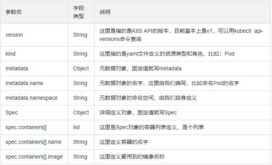
apiVersion: group/version / / indicates which group and version the api resource belongs to. A group can have multiple versions
###Kubectl API versions / / query command
kind: / / mark the resource type created. k8s it mainly supports the following resource categories: Pod,ReplicaSet,Deployment,StatefulSet,DaemonSet,Job,Cronjob
Metadata: / / metadata
Name: / / object name
Namespace: / / which namespace does the object belong to
labels: / / specify the resource label, which is a kind of key value data
spec: / / define the expected state of the target resource
###kubectl explain pod / / query help documents
### kubectl explain pod.spec / / query pod Spec details
### kubectl explain pod.spec.containers / / query pod Details of spec.containers
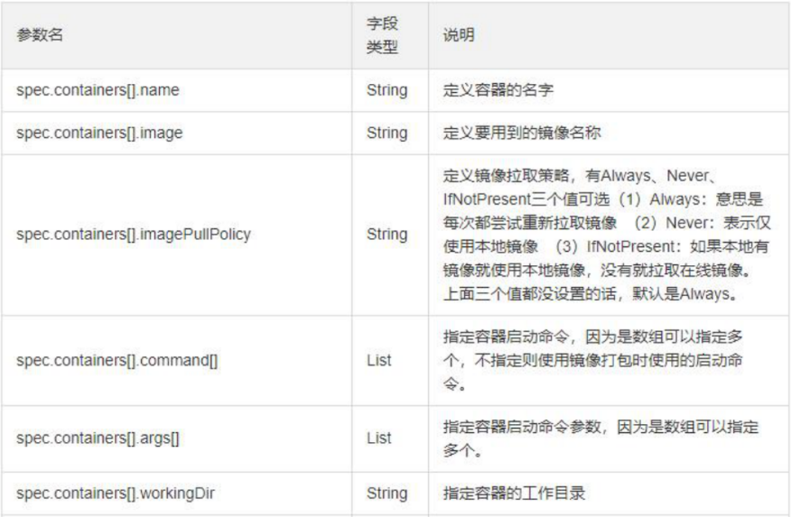
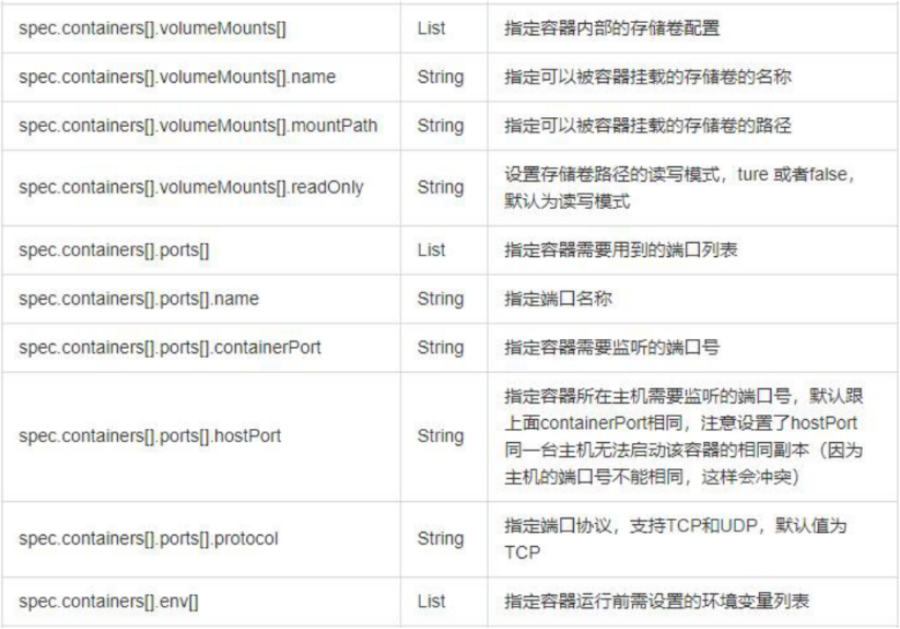
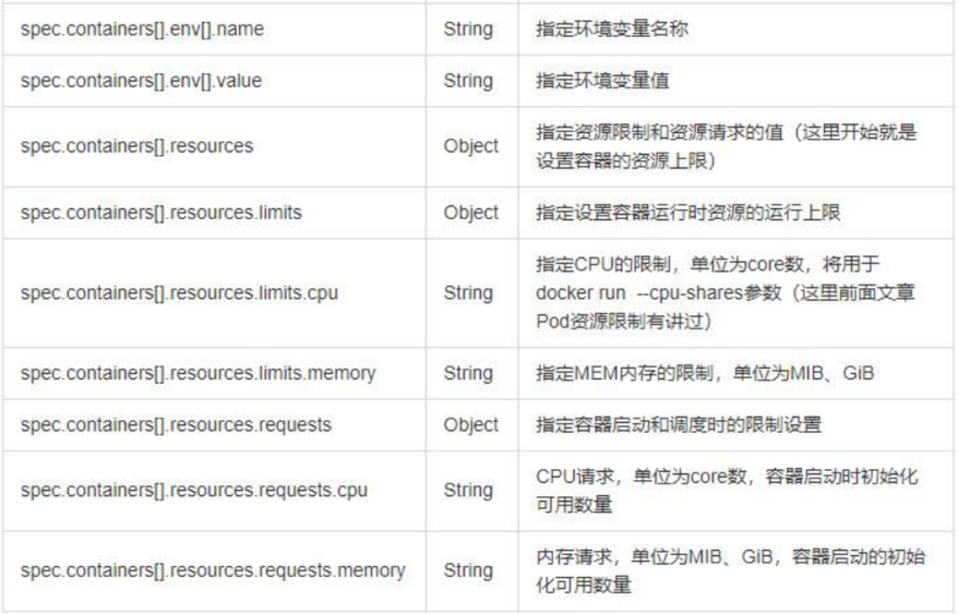
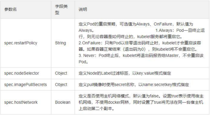
2. Parameter details in resource list
3. Resource list example:
[root@server2 pod]# vim demo.yaml
  1 apiVersion: v1
  2 kind: Pod
  3 metadata:
  4   name: demo
  5 spec:
  6   containers:
  7   - name: myapp           #Create the first container named myapp
  8     image: myapp:v1
  9     imagePullPolicy: IfNotPresent
 10     ports:
 11     - name: http
 12       containerPort: 80   #Port in container
 13       hostPort: 80        #Host port
 14     resources:            #Set the upper limit of resources that the container can allocate from the node
 15       limits:
 16         cpu: 1
 17         memory: 200Mi
 18       requests:             #Set the lower resource limit. If the node does not meet the requirements, it cannot run
 19         cpu: 0.5
 20         memory: 100Mi
 21   - name: busybox         #Create a second container called busybox
 22     image: busyboxplus
 23     imagePullPolicy: IfNotPresent
 24     stdin: true         #The application container needs to give him a terminal
 25     tty: true           #Both are terminal settings
 26
 27
 28   nodeSelector:           #Specify the node on which to run
 29     kubernetes.io/hostname: server3
 30   hostNetwork: true       #The default value is false. Setting it to true indicates that the host network is used, which is similar to the host mode in docker
5, Pod life cycle
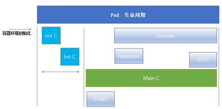
1. Pod life cycle structure diagram
Initialize container to Init_C. It can be one or multiple; The initialization container runs successfully and exits. Then the main container main will be run_ C; The main container has a life cycle from Startup to shutdown, so there is a survival probe "Liveness" to judge whether the main container is in the survival state, and "running" will be displayed when the container is alive; The READY probe "readiness" is used to detect whether the container is READY. When it is READY, "READY" will be displayed.
Pod can contain multiple containers in which applications run. At the same time, pod can also have one or more Init containers started before the application container.
Init containers are very similar to ordinary containers, except for the following two points: (1) they always run to completion. (2)Init containers do not support Readiness because they must be run before Pod is ready. Each init container must run successfully before the next one can run.
If the Init container of the Pod fails, Kubernetes will restart the Pod continuously until the Init container succeeds. However, if the restart policy value corresponding to Pod is Never, it will not restart.
2. Official documentation of Pod's life cycle
3. Init container
What can Init container do?
The Init container can contain some utilities or personalized code that does not exist in the application container during installation.
The Init container can safely run these tools to prevent them from reducing the security of the application image.
The creator and deployer of application image can work independently, and there is no need to jointly build a separate application image.
The Init container can run in a file system view different from the application container in the Pod. Therefore, the Init container can have access to Secrets, while the application container cannot.
Because the Init container must run before the application container starts, the Init container provides a mechanism to block or delay the start of the application container until a set of prerequisites are met. Once the preconditions are met, all application containers in the Pod will start in parallel.
4. init container instance
Note: (1) as long as the statement defining the init container exists in the yml script, it will be executed first, regardless of the writing order. (2) The image pulled in the yml script will be automatically pulled from the local warehouse. Only when the local warehouse does not exist will it be pulled from the external network. If the version is not specified, it is the latest version by default
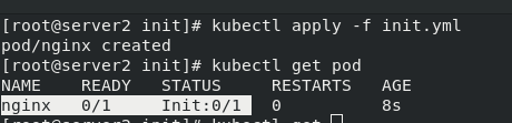
[root@server2 init]# vim init.yml
  1 apiVersion: v1
  2 kind: Pod
  3 metadata:
  4   name: nginx
  5   labels:
  6     app: nginx
  7 spec:
  8   containers:
  9     - name: nginx
 10       image: nginx
 11       imagePullPolicy: IfNotPresent
 12   initContainers:
 13     - name: init-container
 14       image: busybox
 15       command: ["/bin/sh", "-c", "until nslookup myservice.default.svc.cluster.local; do echo waiting for myservice; sleep 2; done"]
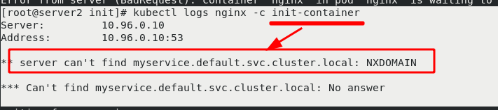
This is because there is no micro service in the initialization container init, that is, service parsing, which makes the initialization container unable to complete and the main container nginx unable to start.
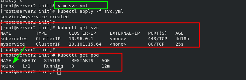
Write an svc file with the pod name "myservice". After writing, start svc yml. The main container nginx is ready for normal operation. After the main container is initialized, it stops.
As long as svc is created, parsing will be provided in the cluster. After svc stops, parsing will not be available!!! Therefore, svc is prepared for initializing containers!!!
[root@server2 init]# vim svc.yml
  1 apiVersion: v1
  2 kind: Service
  3 metadata:
  4   name: myservice                #The port can be set arbitrarily, but the service name should be set well
  5 spec:
  6   ports:
  7   - protocol: TCP
  8     port: 80
  9     targetPort: 80
Test svc parsing:
Method 1:
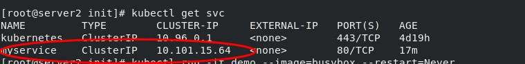
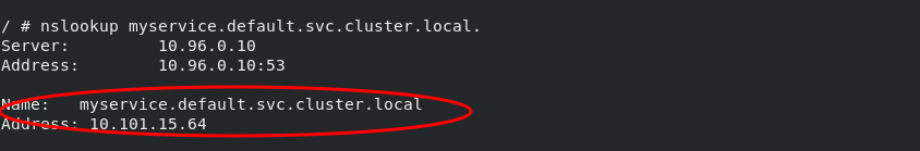
[root@server2 init]# kubectl get svc
NAME         TYPE        CLUSTER-IP     EXTERNAL-IP   PORT(S)   AGE
kubernetes   ClusterIP   10.96.0.1      <none>        443/TCP   4d19h
myservice    ClusterIP   10.101.15.64   <none>        80/TCP    17m

[root@server2 init]# kubectl run -it demo --image=busybox --restart=Never
If you don't see a command prompt, try pressing enter.
/ # nslookup myservice                        #The first parsing failed
Server:		10.96.0.10
Address:	10.96.0.10:53
** server can't find myservice.default.svc.cluster.local: NXDOMAIN

/ # nslookup myservice.default.svc.cluster.local.            #The second parsing succeeded
Server:		10.96.0.10
Address:	10.96.0.10:53

Name:	myservice.default.svc.cluster.local
Address: 10.101.15.64
Method 2:
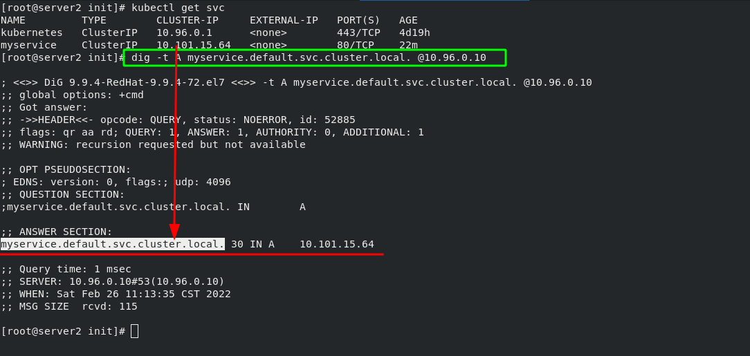
dig -t A myservice.default.svc.cluster.local. @10.96.0.10 #The last IP address indicates the IP to which the service is assigned by the cluster
Probe 5
There are three detection methods:
The probe is a periodic diagnosis of the container performed by kubelet.
ExecAction: executes the specified command in the container. If the return code is 0 when the command exits, the diagnosis is considered successful.
TCPSocketAction: TCP checks the IP address of the container on the specified port. If the port is open, the diagnosis is considered successful.
HTTPGetAction: execute an HTTP Get request on the IP address of the container on the specified port and path. If the status code of the response is greater than or equal to 200 and less than 400, the diagnosis is considered successful.
Each probe will get one of the following three results:
Success: the container passed the diagnosis. Failed: container failed diagnostics. Unknown: the diagnosis failed and no action will be taken.
There are three types of probes:
Kubelet can choose whether to execute the three probes running on the container and react
livenessProbe: indicates whether the container is running. If the survival probe fails, kubelet will kill the container and the container will be affected by its restart strategy. If the container does not provide a survival probe, the default state is Success.
readinessProbe: indicates whether the container is ready for Service requests. If the ready probe fails, the endpoint controller will delete the IP address of the Pod from the endpoints of all services matching the Pod. The ready state before the initial delay defaults to Failure. If the container does not provide a ready probe, the default state is Success.
startupProbe: indicates whether the application in the container has been started. If a startup probe is provided, all other probes are disabled until it succeeds. If the probe fails to start, kubelet will kill the container, and the container will restart according to its restart policy. If the container does not provide a start probe, the default status is Success.
Restart policy PodSpec:
There is a restartPolicy field in. The possible values are Always, OnFailure and Never. The default is Always.
Pod's life:
Generally, Pod will not disappear until they are artificially destroyed, which may be a person or controller.
It is recommended that you create an appropriate controller to create the Pod instead of creating the Pod yourself. Because a single Pod cannot recover automatically in case of machine failure, but the controller can.
Three controllers are available:
(1) use job to run Pod that is expected to terminate, such as batch calculation. Job is only applicable to Pod whose restart policy is OnFailure or Never.
(2) use ReplicationController, ReplicaSet and Deployment, such as Web server, for Pod that is not expected to be terminated. ReplicationController is only applicable to pods with restartPolicy of Always.
(3) provide machine specific system services and run a Pod for each machine using DaemonSet.
6. Examples of live and ready probes
The survival probe detects whether port 80 is available 2 seconds after the image is started. It detects it every 3 seconds. A timeout of 1 second is allowed for each detection
The ready probe detects whether the "test.html" file exists in the default release directory through port 80. The detection rules are the same as above. After passing the test, convey the ready instruction.
[root@server2 init]# vim liveness.yml
  1 apiVersion: v1
  2 kind: Pod
  3 metadata:
  4   labels:
  5     test: liveness
  6   name: liveness-http
  7 spec:
  8   containers:
  9   - name: liveness
 10     image: nginx
 11     imagePullPolicy: IfNotPresent
 12     livenessProbe:              #Survival probe
 13       tcpSocket:
 14         port: 80
 15       initialDelaySeconds: 2    #Detection after image startup delay of 2 seconds
 16       periodSeconds: 3          #Detect every 3 seconds
 17       timeoutSeconds: 1         #Probe timeout
 18     readinessProbe:             #Ready probe
 19       httpGet:
 20         path: /test.html
 21         port: 80
 22       initialDelaySeconds: 2
 23       periodSeconds: 3
 24       timeoutSeconds: 1
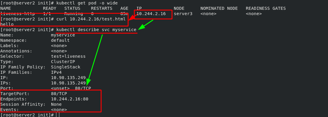
Create an SVC YML service, used to expose the port of pod. The micro service selects the pod through the tag, which is used to show the ports in the cluster to the outside world. When the pod status is not ready, the pod will not be found by the micro service. Microservices have the function of automatic discovery and load balancing on the back end.
[root@server2 init]# vim svc.yml
  1 apiVersion: v1
  2 kind: Service
  3 metadata:
  4   name: myservice
  5 spec:
  6   selector:
  7     test: liveness
  8   ports:
  9   - protocol: TCP
 10     port: 80              #Service port
 11     targetPort: 80        #pod / port in container
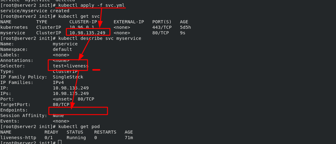
Since the ready probe cannot detect the "test.html" file in the nginx publishing directory, the pod cannot run yet. After entering the pod (the pod name is liveness HTTP), create the "test.html" file in the publishing directory and check the pod status again. It is ready. Checked by curl command, it is also ready. Once the pod is ready, it will be automatically discovered by the svc of myservice.
[root@server2 init]# kubectl exec -it liveness-http -- bash
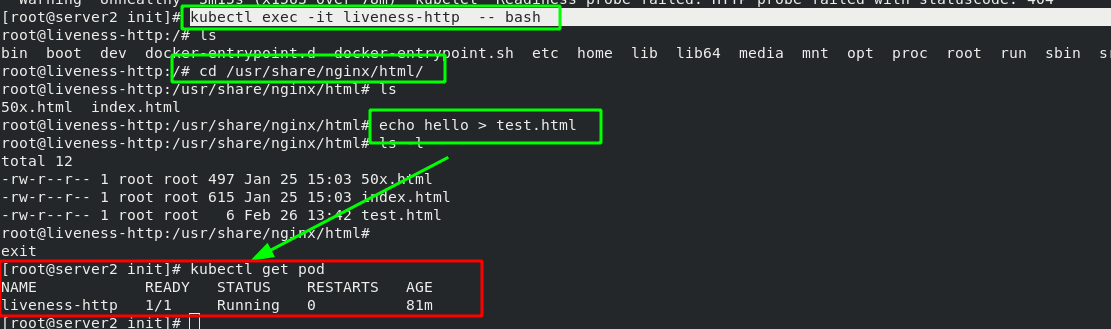
Note: the ready probe will always exist. When the conditions detected by the ready probe are not met, the pod service will be stopped immediately, and the pod service will not be allowed to run until the conditions are met again. Microservices are used to discover ready pods and realize back-end load balancing.
6, Controller
1. Basic concept of controller
Pod classification:
(1) Autonomous Pod: it is managed by the user and will not be created after exiting
(2) Pod managed by the controller: maintain the number of copies of the pod throughout the life cycle of the controller
Controller type:
Replication Controller and ReplicaSet, Deployment, DaemonSet, StatefulSet, Job, CronJob, HPA(Horizontal Pod Autoscaler)
Detailed comparison of controller types:
| Replication Controller and ReplicaSet | ReplicaSet is the next generation of Replication Controller, which is officially recommended. The only difference between ReplicaSet and Replication Controller is selector support. ReplicaSet supports new set based selector requirements. ReplicaSet ensures that a specified number of Pod replicas are running at any time. Although ReplicaSets can be used independently, today it is mainly used by Deployments as a mechanism to coordinate Pod creation, deletion and update. |
| Deployment | Deployment provides a declarative definition method for Pod and ReplicaSet. Typical application scenarios: used to create Pod and ReplicaSet, rolling update and rollback, capacity expansion and shrinkage, pause and resume |
| DaemonSet | The daemon set ensures that a copy of the Pod is running on all (or some) nodes. When a node joins the cluster, it will also add a Pod for them. When a node is removed from the cluster, these pods will also be recycled. Deleting a DaemonSet will delete all pods it creates. Typical usage of DaemonSet: Run the clustered storage DaemonSet on each node, such as glusterd, ceph. Run the log collection daemon set on each node, such as fluent D and logstash. Run monitoring DaemonSet on each node, such as Prometheus Node Exporter, zabbix agent, etc A simple usage is to start a daemon set on all nodes, which will be used as each type of daemon. A slightly complicated usage is to use multiple daemonsets for each daemon type separately, but with different flags, and different memory and CPU requirements for different hardware types. |
| StatefulSet | StatefulSet is an API object used to manage the workload of stateful applications. Applications with unequal relationships between instances and dependencies on external data are called "stateful applications" Stateful set is used to manage Deployment and extend a group of pods, and can provide * sequence number and uniqueness guarantee * for these pods. StatefulSets are valuable for applications that need to meet one or more of the following requirements: Stable and unique network identifier. Stable and persistent storage. Orderly and elegant deployment and scaling. Orderly and automatic rolling update. |
| Job | Execute batch processing tasks and only execute the task once to ensure the successful completion of one or more pods of the task. |
| CronJob | Cron Job creates Jobs based on time scheduling. A CronJob object is like a line in a crontab (cron table) file. It is written in Cron format and executes Jobs periodically at a given scheduling time. |
| HPA | Automatically adjust the number of pods in the service according to the resource utilization to realize the automatic scaling of Pod level. |
2. Official documentation of the controller
Workload resources | Kubernetes https://kubernetes.io/zh/docs/concepts/workloads/controllers/
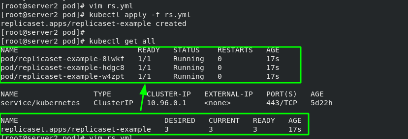
3. ReplicaSet controller example - container number detection (automatically created when container hangs)
[root@server2 pod]# vim rs.yml
  1 apiVersion: apps/v1
  2 kind: ReplicaSet                        #Specify controller type
  3 metadata:
  4     name: replicaset-example
  5 spec:
  6   replicas: 3                           #The number of copies is 3 (capacity can be expanded or reduced at will)
  7   selector:                             #Match label
  8     matchLabels:
  9       app: nginx                        #The matching tag is nginx
 10   template:                             #Template template is used to apply nginx tags to all container s under the template
 11     metadata:
 12       labels:
 13         app: nginx
 14     spec:                               #Define container
 15       containers:
 16       - name: nginx
 17         image: nginx
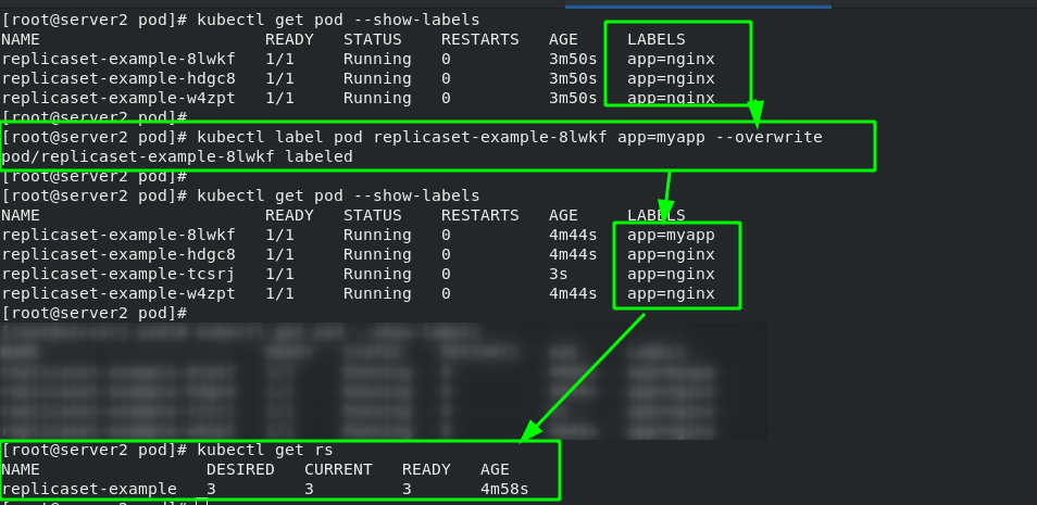
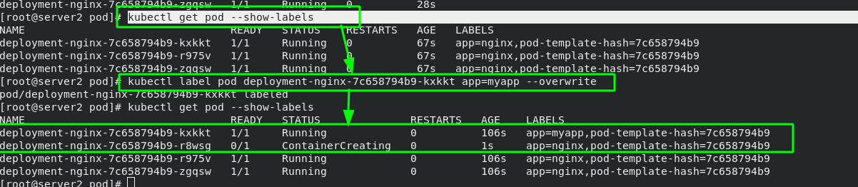
#Change pod label
[root@server2 pod]# kubectl label pod replicaset-example-8lwkf app=myapp --overwrite
#Show all pod Tags
[root@server2 pod]# kubectl get pod --show-labels
#Display rs controller
[root@server2 pod]# kubectl get rs
rs manages containers based on "tag items". Only tags that comply with "app=nginx" belong to rs management. After changing the pod tag, the original container ID has not changed, but it has been separated from the management of rs. in order to ensure that there are three copies, rs will create another container.
4. Deployment controller example - version rollback
[root@server2 pod]# vim deploy.yml
  1 apiVersion: apps/v1
  2 kind: Deployment                        #Specify controller type
  3 metadata:
  4   name: deployment-nginx
  5 spec:
  6   replicas: 3
  7   selector:
  8     matchLabels:
  9       app: nginx
 10   template:
 11     metadata:
 12       labels:
 13         app: nginx
 14     spec:
 15       containers:
 16       - name: nginx
 17         image: nginx:latest
The Deployment controller is based on rs controller. The basic function is the same as that of rs controller, with the label of container as the standard. After changing the container label, a new container is also created.
The main function of Deployment is to change the image version (upgrade or rollback)
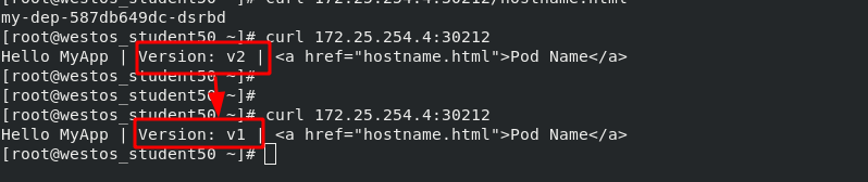
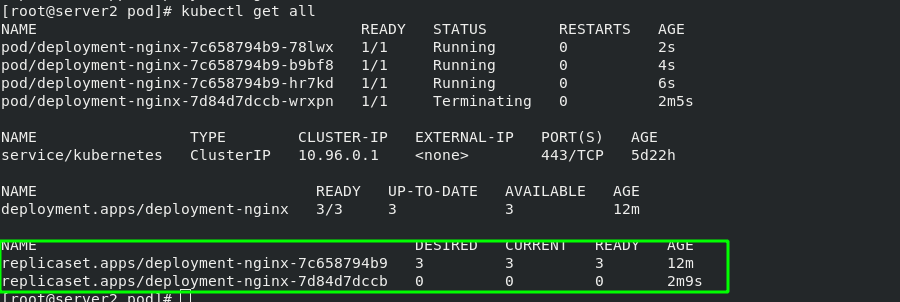
After the mirror version is changed and takes effect again, you will find that there will be history information behind the controller.
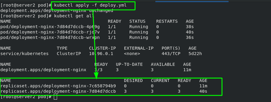
If you change back to the previous image version, the container can be directly rolled back to the previous version!!!
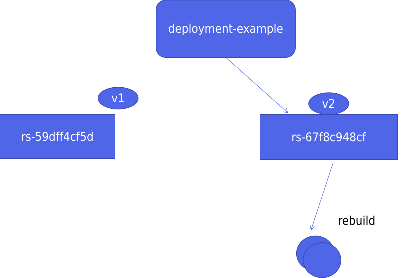
The basic structure diagram of Deployment is as follows:
When the version changes from v1 to v2, a new rs controller will be created, and a new container will be created through the rs controller of v2, while keeping the rs controller of v1; When the version is rolled back to v1, the container will be created directly from the rs controller of v1, which greatly saves resources.
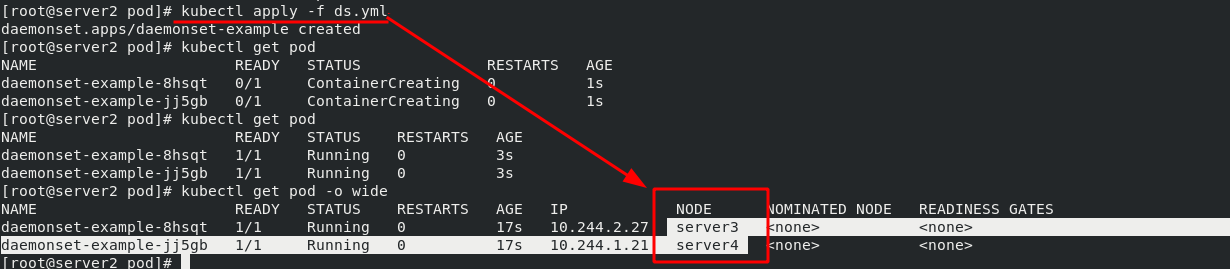
5. DaemonSet controller example - ensure that a copy of a Pod is running on all (or some) nodes
[root@server2 pod]# vim ds.yml
  1 apiVersion: apps/v1
  2 kind: DaemonSet
  3 metadata:
  4   name: daemonset-example
  5   labels:
  6     k8s-app: zabbix-agent
  7 spec:
  8   selector:
  9     matchLabels:
 10       name: zabbix-agent
 11   template:
 12     metadata:
 13       labels:
 14         name: zabbix-agent
 15     spec:
 16       containers:
 17       - name: zabbix-agent
 18         image: nginx
There is no need to set the number of copies here. It will automatically add a mirror for each node.
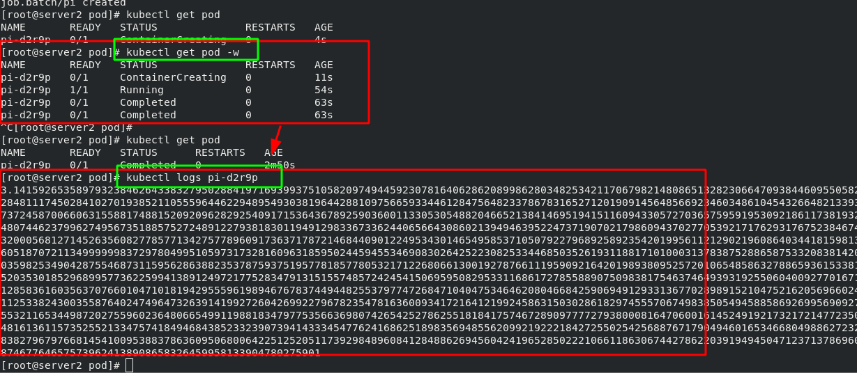
6. Job controller example -- execute batch tasks, execute tasks only once, and exit after completion
[root@server2 pod]# vim job.yml
  1 apiVersion: batch/v1
  2 kind: Job                               #Controller type
  3 metadata:
  4   name: pi
  5 spec:
  6   template:
  7     spec:
  8       containers:
  9       - name: pi
 10         image: perl                             #The image name is perl
 11         command: ["perl",  "-Mbignum=bpi", "-wle", "print bpi(2000)"]           #2000 bits after calculating pi
 12       restartPolicy: Never
 13   backoffLimit: 4
#View pod operation information
[root@server2 pod]# kubectl get pod -w
NAME       READY   STATUS              RESTARTS   AGE
pi-d2r9p   0/1     ContainerCreating   0          11s

#View the running results through logs
[root@server2 pod]# kubectl logs pi-d2r9p
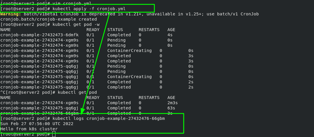
7. Cronjob controller example - cronjob creates scheduled tasks and periodically executes jobs at a given scheduling time
[root@server2 pod]# vim cronjob.yml
  1 apiVersion: batch/v1beta1
  2 kind: CronJob
  3 metadata:
  4   name: cronjob-example
  5 spec:
  6   schedule: "* * * * *"                         #Execute the job at the time of "time sharing day month week"
  7   jobTemplate:
  8     spec:
  9       template:
 10         spec:
 11           containers:
 12           - name: cronjob
 13             image: busybox
 14             args:
 15             - /bin/sh
 16             - -c
 17             - date; echo Hello from k8s cluster        #Print this sentence every time through busybox
 18           restartPolicy: OnFailure
Execute every other minute and output the statement.
7, Service - micro service
1. Service concept
A Service can be regarded as a group of external access interfaces of pods that provide the same Service (for port exposure in the pod). With the help of Service, applications can easily realize Service discovery and load balancing.
By default, the service only supports 4-tier load balancing capabilities, without 7-tier functions. (it can be realized through Ingress)
Type of service:
ClusterIP: the default value, k8s the virtual IP automatically assigned by the system to the service, can only be accessed inside the cluster.
NodePort: expose the Service to the outside through the port on the specified Node to access any one
NodeIP:nodePort will be routed to ClusterIP.
LoadBalancer: on the basis of NodePort, create an external load balancer with the help of cloud provider and forward the request to < nodeip >: NodePort. This mode can only be used on ECs.
ExternalName: forwards the service to the specified domain name through DNS CNAME record (set through spec.externlName).
Official documents:
Service is implemented by Kube proxy components and iptables.
Kube proxy processes the Service through iptables. It needs to set quite a lot of iptables rules on the host. If the host has a large number of pods (and when adding or deleting pods), constantly refreshing iptables rules will consume a lot of CPU resources.
IPVS mode service enables K8s cluster to support more orders of Pod.
Open the ipvs mode of Kube proxy:
#Install ipvsadm manager on all nodes
yum install -y ipvsadm

#Modify IPVS mode
kubectl edit cm kube-proxy -n kube-system
mode: "ipvs"

#Update Kube proxy pod
kubectl get pod -n kube-system |grep kube-proxy | awk '{system("kubectl delete pod "$1" -n kube-system")}'
After the update, you can see that the policy has been updated through ipvsadm, as shown below:
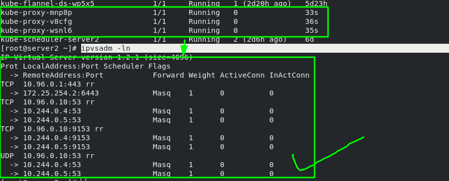
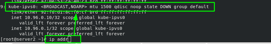
After the setting is completed, the network card options of the host computer will have more Kube IPVS interfaces. All added svc addresses will be added to the IP of this interface
2. Deployment controller + svc service
[root@server2 pod]# vim deploy.yml
  1 apiVersion: apps/v1
  2 kind: Deployment
  3 metadata:
  4   name: deployment-nginx
  5 spec:
  6   replicas: 3
  7   selector:
  8     matchLabels:
  9       app: nginx
 10   template:
 11     metadata:
 12       labels:
 13         app: nginx
 14     spec:
 15       containers:
 16       - name: nginx
 17         image: myapp:v1
 18 ---                                #Create micro Service
 19 apiVersion: v1
 20 kind: Service
 21 metadata:
 22   name: myservice
 23 spec:
 24   selector:
 25     app: nginx                    #Note that the label is consistent with the label of the deploy controller defined above
 26   ports:
 27   - protocol: TCP
 28     port: 80              #Service port
 29     targetPort: 80        #pod / port in container
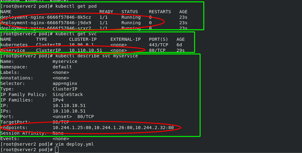
Viewing the forwarding rules through ipvsadm, the virtual IP address obtained by svc can be scheduled to three containers in the background through rr algorithm.
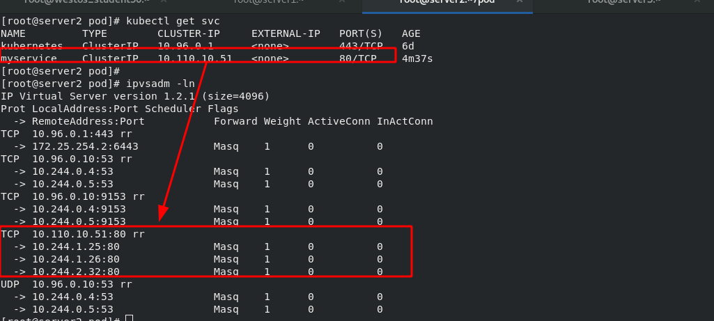
In this way, you can achieve load balancing without frequently refreshing the iptables policy, which will change dynamically with the IP of the container
8, k8s network communication
k8s connect other plug-ins through CNI interface to realize network communication. At present, the popular plug-ins include flannel, calico, etc. CNI plug-in storage location: # cat / etc / CNI / net d/10-flannel. conflist
The solutions used by the plug-in are as follows:
Virtual bridge, virtual network card, multiple containers share a virtual network card for communication.
Multiplexing: MacVLAN, where multiple containers share a physical network card for communication.
Hardware exchange: SR-LOV, a physical network card can virtualize multiple interfaces, which has the best performance.
Inter container communication: the communication between multiple containers in the same pod can be realized through lo;
Communication between pod s:
The pod s of the same node forward data packets through the cni bridge.
The communication between pod s of different nodes needs the support of network plug-ins.
Communication between pod and service: communication is realized through iptables or ipvs. ipvs cannot replace iptables, because ipvs can only do load balancing, not nat conversion.
pod and extranet communication: MASQUERADE of iptables.
Communication between Service and external clients of the cluster: (ingress, nodeport, loadbalancer)
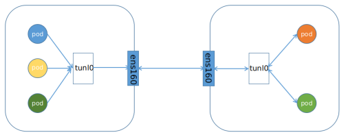
1. Principle of cross host communication in Flannel vxlan mode
2. flannel network
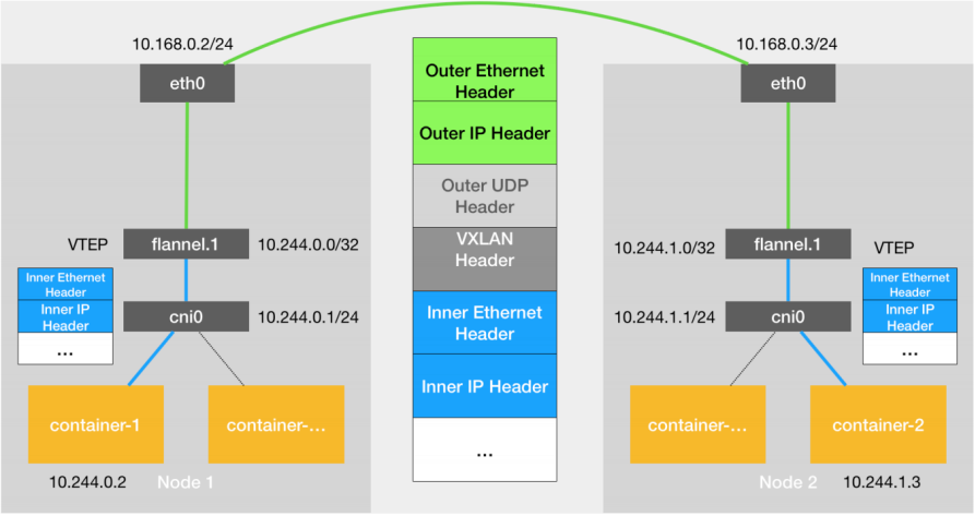
VXLAN, Virtual Extensible LAN (Virtual Extensible LAN), is a network virtualization technology supported by Linux itself. VXLAN can completely realize encapsulation and de encapsulation in the kernel state, so as to build an Overlay Network through the "tunnel" mechanism.
VTEP: VXLAN Tunnel End Point. In Flannel, the default value of VNI is 1, which is why the VTEP devices of the host are called Flannel 1. The reason for the failure. Cni0: bridge device. Each time a pod is created, a pair of Veth pairs will be created. One end is eth0 in pod and the other end is the port (network card) in cni0 bridge.
Flannel.1: TUN device (virtual network card) is used to process vxlan messages (packet and unpacking). The pod data traffic between different node s is sent from the overlay device to the opposite end in the form of tunnel.
Flanneld: flanneld runs flanneld in each host as an agent. It will obtain a small network segment subnet from the network address space of the cluster for the host, from which the IP addresses of all containers in the host will be allocated. At the same time, flanneld monitors the K8s cluster database for flannel 1. The device provides necessary mac, IP and other network data information when encapsulating data.
Principle of flannel network:
When the container sends an IP packet, it is sent to the cni bridge through veth pair, and then routed to the local flannel 1. Process the equipment.
VTEP devices communicate through layer-2 data frames. After receiving the original IP packet, the source VTEP device adds a destination MAC address to it, encapsulates it into an internal data frame and sends it to the destination VTEP device.
The internal data frame cannot be transmitted on the two-layer network of the host. The Linux kernel needs to further encapsulate it into an ordinary data frame of the host, carrying the internal data frame and transmitting it through the eth0 of the host.
Linux will add a VXLAN header in front of the internal data frame. There is an important flag called VNI in the VXLAN header, which is an important flag for VTEP to identify whether a data frame should be handled by itself.
flannel.1. The device only knows the flannel at the other end 1 the MAC address of the device, but I don't know what the corresponding host address is. In the linux kernel, the forwarding basis of network devices comes from the forwarding database of FDB, the flannel The FDB information corresponding to 1 bridge is maintained by the flanneld process.
The linux kernel adds a layer-2 data frame header in front of the IP packet, fills in the MAC address of the target node, and the MAC address is obtained from the ARP table of the host.
Flannel 1 device can send the data frame from eth0, and then through the host network to the eth0 device of the target node. The target host kernel network stack will find that this data frame has VXLAN Header, and VNI is 1. The Linux kernel will unpack it, get the internal data frame, and give it to the local flannel according to the VNI value 1 equipment processing, flannel 1 unpack and send it to the cni bridge according to the routing table, and finally reach the target container.
3. flannel supports multiple back ends
Vxlan:
vxlan / / message encapsulation, default
Directrouting / / direct routing. vxlan is used for cross network segments, and host GW mode is used for the same network segment.
Host GW: / / the host gateway has good performance, but it can only be used in the layer-2 network and does not support cross network. If there are thousands of pods, it is easy to produce broadcast storms, which is not recommended
UDP: / / poor performance, not recommended
Configure flannel:
#Configure flannel
[root@server2 ~]# kubectl edit cm -n kube-system kube-flannel-cfg
27 net-conf.json: |
28 {
29 "Network": "10.244.0.0/16",
30 "Backend": {
31 "Type": "host-gw" #Change from xvlan to host GW
32 }
33 }
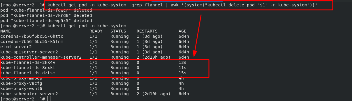
#Delete the old flannel, and the controller will re-establish the flannel according to the new configuration
[root@server2 ~]# kubectl get pod -n kube-system |grep flannel | awk '{system("kubectl delete pod "$1" -n kube-system")}'
4. calico network plug-in (details will be introduced later)
Official website: https://docs.projectcalico.org/getting-started/kubernetes/self-managed-onprem/onpremises
calico introduction:
flannel implements network communication, and calico's feature is the isolation between pod s.
Routing through BGP, but the topology calculation and convergence of large-scale endpoints often require a certain amount of time and computing resources.
Pure three-tier forwarding, without any NAT and overlay in the middle, has the best forwarding efficiency.
Calico only relies on three-tier routing. Calico's less dependency makes it suitable for all VM, Container, white box or mixed environment scenarios.
calico network architecture:
Felix: monitor the storage acquisition events in the ECTD center. After the user creates a pod, Felix is responsible for setting its network card, IP and MAC, and then write a note in the routing table of the kernel, indicating that this IP should go to this network card. Similarly, if the user makes an isolation policy, Felix will also create the policy into the ACL to achieve isolation.
BIRD: a standard routing program. It will get which IP's routing has changed from the kernel, and then spread to other host computers through the standard BGP routing protocol to let the outside world know that this IP is here and come here when routing.

5. Headless Service "Headless Service"
Headless Service does not need to assign a VIP, but directly resolves the IP address of the proxy Pod in the form of DNS records. Domain name format: $(servicename)$ (namespace). svc. cluster. local
Headless Service instance:
[root@server2 service]# vim headless.yml
  1 apiVersion: v1
  2 kind: Service
  3 metadata:
  4   name: nginx-svc
  5 spec:
  6   ports:
  7     - name: http
  8       port: 80
  9       targetPort: 80
 10   selector:
 11       app: nginx
 12   clusterIP: None
6. The second way to access services from outside is LoadBalancer type services
The second way to access services from outside is applicable to Kubernetes services on the public cloud. At this time, you can specify a Service of LoadBalancer type. (the first is NodePort mode and the second is LoadBalancer mode)
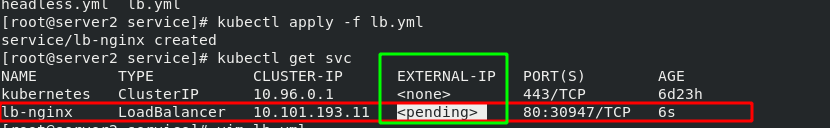
[root@server2 service]# vim lb.yml
  1 apiVersion: v1
  2 kind: Service
  3 metadata:
  4   name: lb-nginx
  5 spec:
  6   ports:
  7     - name: http
  8       port: 80
  9       targetPort: 80
 10   selector:
 11       app: nginx
 12   type: LoadBalancer
After the service is submitted, Kubernetes will call CloudProvider to create a load balancing service for you on the public cloud, and configure the IP address of the proxy Pod to the load balancing service as the back end. In this example, "EXTERNAL-IP" can be understood as a load balancer.
Note: the "EXTERNAL-IP" will be set in the next section
Basic structure diagram:
(1) The cloud environment is as follows:
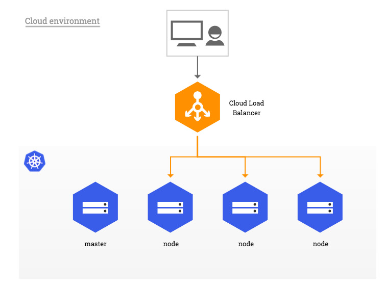
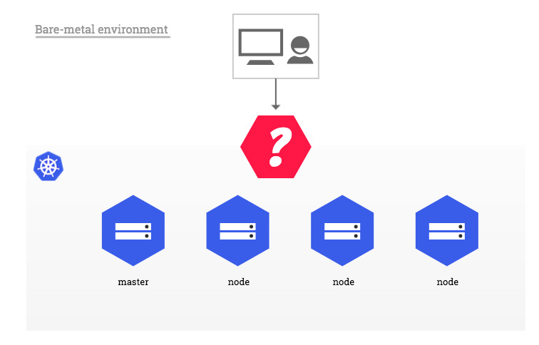
(2) single machine environment: bare metal
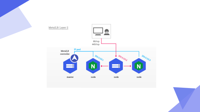
7. Deploying Metallb-layer2 environment on a stand-alone computer
Official documents:
MetalLB, bare metal load-balancer for Kubernetes https://metallb.universe.tf/installation/
Start an svc service and add the nginx image controlled by the deployment controller to facilitate subsequent testing.
[root@server2 service]# vim lb.yml
  1 apiVersion: v1
  2 kind: Service
  3 metadata:
  4   name: lb-nginx
  5 spec:
  6   ports:
  7     - name: http
  8       port: 80
  9       targetPort: 80
 10   selector:
 11       app: nginx
 12   type: LoadBalancer
 13
 14 ---
 15 apiVersion: apps/v1
 16 kind: Deployment
 17 metadata:
 18   name: deployment-nginx
 19 spec:
 20   replicas: 3
 21   selector:
 22     matchLabels:
 23       app: nginx
 24   template:
 25     metadata:
 26       labels:
 27         app: nginx
 28     spec:
 29       containers:
 30       - name: nginx
 31         image: myapp:v1
Deploy metallb-layer2
#Set ipvs mode
kubectl edit configmap -n kube-system kube-proxy
    apiVersion: kubeproxy.config.k8s.io/v1alpha1
    kind: KubeProxyConfiguration
    mode: "ipvs"
    ipvs:
      strictARP: true

#Reload the container for the changes to take effect
kubectl get pod -n kube-system |grep kube-proxy | awk '{system("kubectl delete pod "$1" -n kube-system")}

#Install a new namespace and deploy metallb
kubectl apply -f https://raw.githubusercontent.com/metallb/metallb/v0.12.1/manifests/namespace.yaml
kubectl apply -f https://raw.githubusercontent.com/metallb/metallb/v0.12.1/manifests/metallb.yaml
Note: when deploying metallb, metallb There will be a pull image in yaml file, so you can download the image to the local warehouse first
#Pull image
[root@server1 ~]# docker pull quay.io/metallb/speaker:v0.12.1
[root@server1 ~]# docker pull quay.io/metallb/controller:v0.12.1
#Change mirror label
[root@server1 ~]# docker tag quay.io/metallb/controller:v0.12.1 reg.westos.org/metallb/controller:v0.12.1
[root@server1 ~]# docker tag quay.io/metallb/speaker:v0.12.1 reg.westos.org/metallb/speaker:v0.12.1
#Upload image
[root@server1 ~]# docker push reg.westos.org/metallb/controller:v0.12.1
[root@server1 ~]# docker push reg.westos.org/metallb/speaker:v0.12.1
#Change metallb Get the address of yaml's image
[root@server2 metallb]# vim metallb.yaml
365 image: metallb/speaker:v0.12.1
444 image: metallb/controller:v0.12.1
#Run metallb and view it in the specified namespace
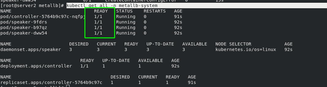
[root@server2 metallb]# kubectl apply -f metallb.yaml
[root@server2 metallb]# kubectl get pod -n metallb-system
NAME READY STATUS RESTARTS AGE
controller-5764b9c97c-nqfpj 0/1 Running 0 14s
speaker-9fdrs 0/1 CreateContainerConfigError 0 15s
speaker-b97qz 0/1 CreateContainerConfigError 0 15s
speaker-dww54 0/1 CreateContainerConfigError 0 15s
Configure address pool:
[root@server2 metallb]# vim config.yaml
  1 apiVersion: v1
  2 kind: ConfigMap
  3 metadata:
  4   namespace: metallb-system
  5   name: config
  6 data:
  7   config: |
  8     address-pools:
  9     - name: default
 10       protocol: layer2
 11       addresses:
 12       - 172.25.254.100-172.25.254.200        #Set as your own IP address pool (external access is required)
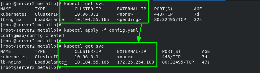
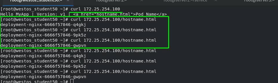
Test: after svc obtains an "EXTERNAL-IP", the external network can directly access this IP to access the background container, and the access is load balanced. The test results are as follows
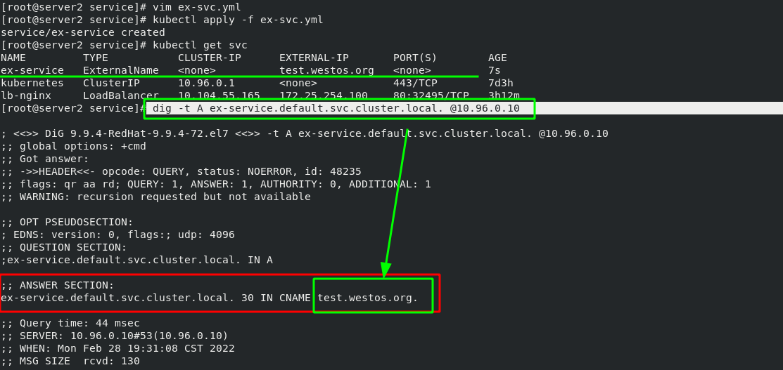
8. The third way to access a service externally is ExternalName
[root@server2 service]# vim ex-svc.yml
  1 apiVersion: v1
  2 kind: Service
  3 metadata:
  4   name: ex-service
  5 spec:
  6   type:  ExternalName
  7   externalName: test.westos.org
Because the IP address of svc in the cluster is always changing, a resolution can be provided to make it relatively fixed; When accessing the external network, you only need to find the domain name to automatically resolve to the svc IP.
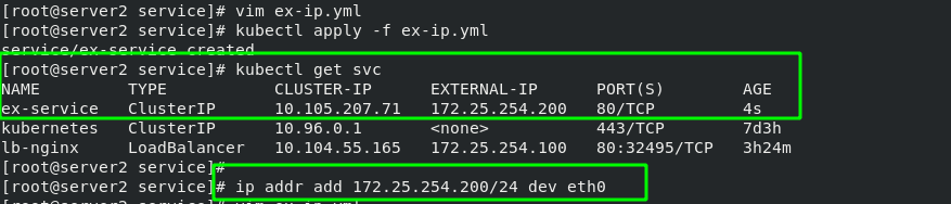
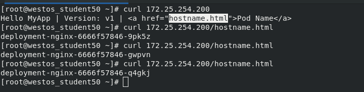
You can also bind an IP directly to svc. After svc is started, you need to manually add an IP address to the node, and then you can access it outside the cluster. It is generally not recommended, which requires high maintenance costs in the later stage.
  1 apiVersion: v1
  2 kind: Service
  3 metadata:
  4   name: ex-service
  5 spec:
  6   selector:
  7     app: nginx
  8   ports:
  9   - name: http
 10     protocol: TCP
 11     port: 80
 12     targetPort: 80
 13   externalIPs:
 14   - 172.25.254.200
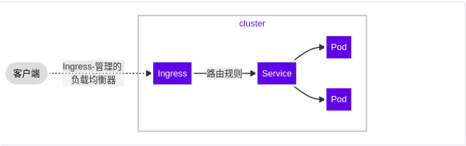
9. Ingress Service -- accessing the internal cluster from the external network
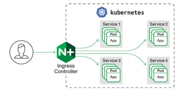
A global load balancing Service set to proxy different backend services is the Ingress Service in Kubernetes.
Ingress consists of two parts: Ingress Controller and ingress service. The Ingress Controller will provide corresponding proxy capabilities according to the ingress object you define.
Various reverse proxy projects commonly used in the industry, such as Nginx, HAProxy, Envoy, traifik, etc., have specially maintained the corresponding progress controller for Kubernetes.
In other words, Ingress is used to load balance svc, and svc is used to load balance pod
Official documents:
(1) Deployment steps of basic ingress structure:
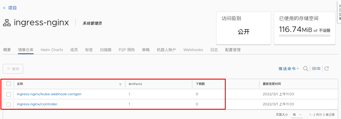
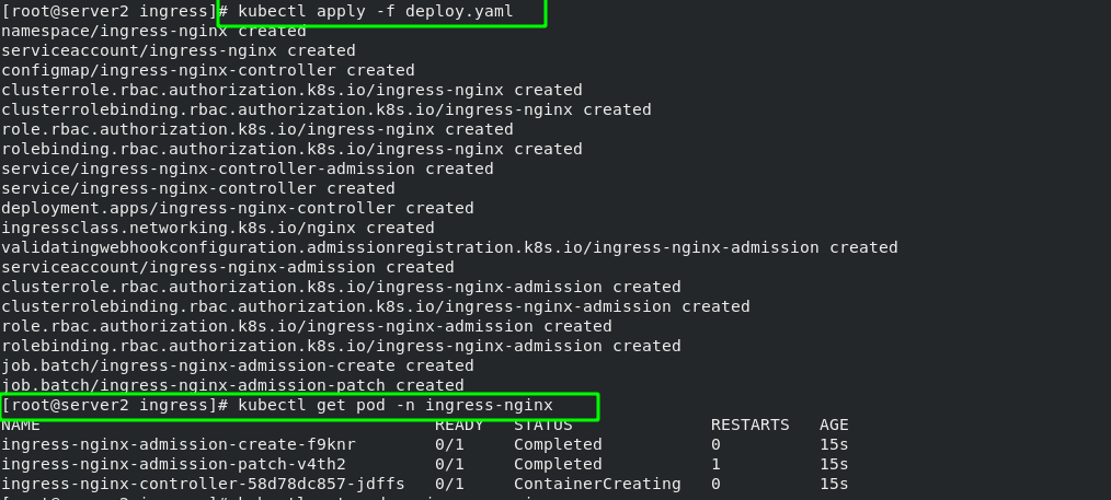
stay server2 in
#Download deploy YML file
wget https://raw.githubusercontent.com/kubernetes/ingress-nginx/controller-v1.1.1/deploy/static/provider/baremetal/deploy.yaml

stay server1 Pull the upper part from the middle deply.yaml Two images required in the file,Modify the tag and upload it to the local warehouse
 1044  docker pull liangjw/ingress-nginx-controller:v1.1.1
 1045  docker pull liangjw/kube-webhook-certgen:v1.1.1
 1046  docker tag liangjw/ingress-nginx-controller:v1.1.1 reg.westos.org/ingress-nginx/controller:v1.1.1
 1047  docker tag liangjw/kube-webhook-certgen:v1.1.1 reg.westos.org/ingress-nginx/kube-webhook-certgen:v1.1.1
 1048  docker push reg.westos.org/ingress-nginx/controller:v1.1.1
 1049  docker push reg.westos.org/ingress-nginx/kube-webhook-certgen:v1.1.1
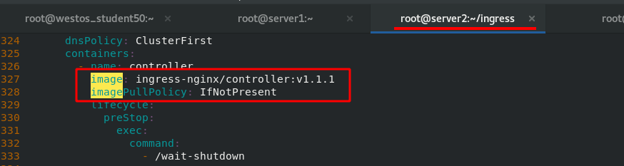
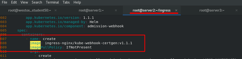
Deploy. In server2 Change the image address in yaml file to the address of private warehouse.
The effect after deployment is as follows:
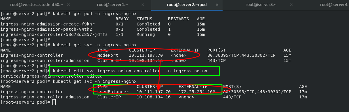
The basic logic is: client - > inress - > svc - > pod. Therefore, you can change the ingress controller to the LoadBalancer mode, which will automatically obtain an IP address and directly access svc from the external network.
The first requirement is to access the "www1.westos.org" domain name on the external host to access the inside of the pod through ingress. Therefore, you need to reset an svc
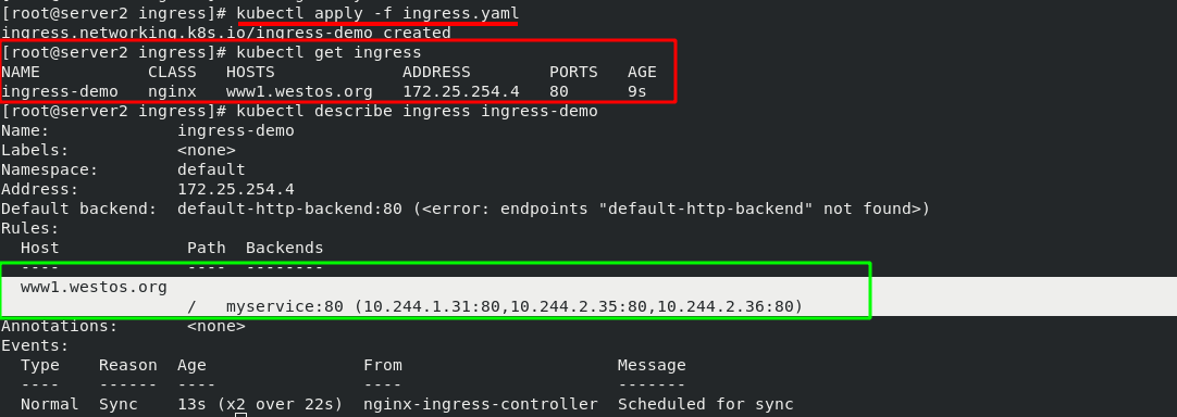
[root@server2 ingress]# cat ingress.yaml
  1 apiVersion: networking.k8s.io/v1
  2 kind: Ingress
  3 metadata:
  4   name: ingress-demo
  5 spec:
  6   ingressClassName: nginx
  7   rules:
  8   - host: www1.westos.org
  9     http:
 10       paths:
 11       - path: /                         #Direct access to the root directory
 12         pathType: Prefix
 13         backend:                #Set the svc of the backend
 14           service:
 15             name: myservice             #The svc name of the backend must match
 16             port:
 17               number: 80

#ingress. After the YML file takes effect, view the details
[root@server2 ingress]# kubectl apply -f ingress.yaml
ingress.networking.k8s.io/ingress-demo created
[root@server2 ingress]# kubectl get ingress
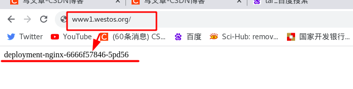
The green box in the following figure shows that when the external network accesses "www1.westos.org", it will automatically access the three pod s on the backend "myservice:80"
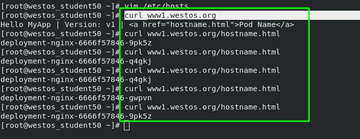
Test on external host:
(2) Inress deployment extension -- domain name based virtual host
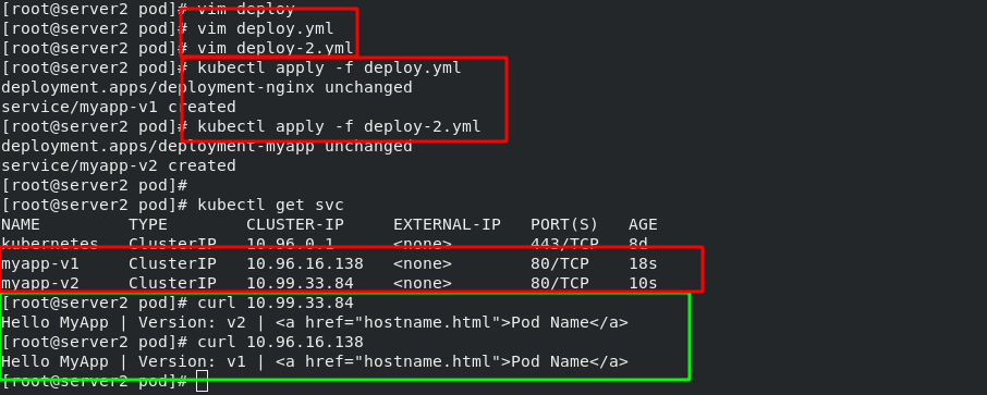
In order to distinguish it from the next experiment, a new experiment domain name is "www2.westos.org" and the svc service name is "myapp svc".
#New svc service
[root@server2 pod]# vim deploy-2.yml
  1 apiVersion: apps/v1
  2 kind: Deployment
  3 metadata:
  4   name: deployment-myapp
  5 spec:
  6   replicas: 3
  7   selector:
  8     matchLabels:
  9       app: myapp
 10   template:
 11     metadata:
 12       labels:
 13         app: myapp
 14     spec:
 15       containers:
 16       - name: myapp
 17         image: myapp:v2
 18 ---
 19 apiVersion: v1
 20 kind: Service
 21 metadata:
 22   name: myapp-svc
 23 spec:
 24   selector:
 25     app: myapp
 26   ports:
 27   - protocol: TCP
 28     port: 80              #Service port
 29     targetPort: 80        #pod / port in container
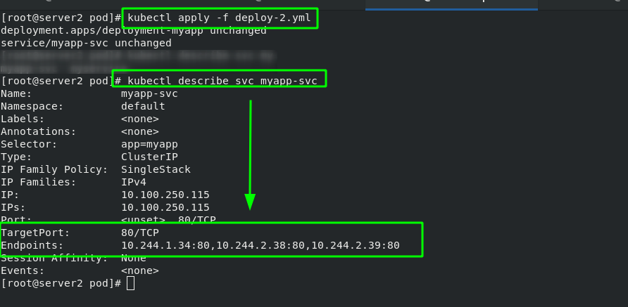
#In the previous ingress Add www2.0 to yaml file westos. Org domain name
[root@server2 ingress]# vim ingress.yaml
 1 apiVersion: networking.k8s.io/v1
  2 kind: Ingress
  3 metadata:
  4   name: ingress-demo
  5 spec:
  6   ingressClassName: nginx
  7   rules:
  8   - host: www1.westos.org
  9     http:
 10       paths:
 11       - path: /                         #Direct access to the root directory
 12         pathType: Prefix
 13         backend:                #Set the svc of the backend
 14           service:
 15             name: myservice             #The svc name of the backend must match
 16             port:
 17               number: 80
 18   - host: www2.westos.org
 19     http:
 20       paths:
 21       - path: /                         #Direct access to the root directory
 22         pathType: Prefix
 23         backend:                #Set the svc of the backend
 24           service:
 25             name: myapp-svc             #The svc name of the backend must match
 26             port:
 27               number: 80

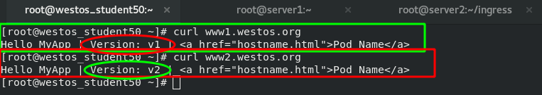
Test: if the two domain names are accessed separately on the external host, they will be dispatched to different SVCS by ingress
(3)ingress examples
Introduction - NGINX Ingress Controllerhttps://kubernetes.github.io/ingress-nginx/examples/
(4)ingress encryption
TLS termination - NGINX Ingress Controller https://kubernetes.github.io/ingress-nginx/examples/tls-termination/ Create a certificate and import kubectl
#Generate certificates and keys
[root@server2 ingress]# openssl req -x509 -sha256 -nodes -days 365 -newkey rsa:2048 -keyout tls.key -out tls.crt -subj "/CN=nginxsvc/O=nginxsvc"
Generating a 2048 bit RSA private key
..............................................................+++
..........+++
writing new private key to 'tls.key'
-----
#Import certificates and keys
[root@server2 ingress]# kubectl create secret tls tls-secret --key tls.key --cert tls.crt
secret/tls-secret created
#View certificates in kubectl
[root@server2 ingress]# kubectl get secrets
NAME                  TYPE                                  DATA   AGE
default-token-tcwmq   kubernetes.io/service-account-token   3      7d21h
tls-secret            kubernetes.io/tls                     2      11s
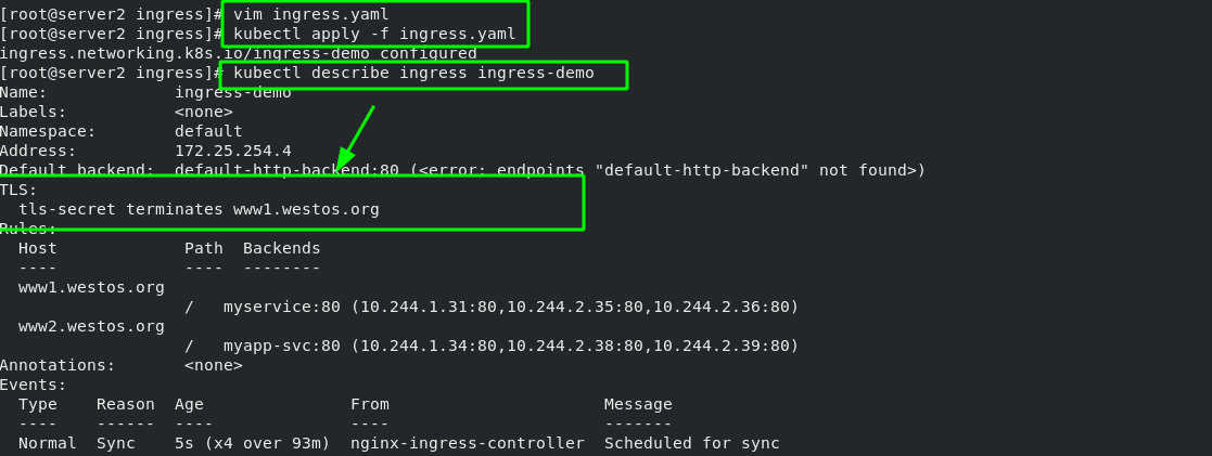
[root@server2 ingress]# vim ingress.yaml
  1 apiVersion: networking.k8s.io/v1
  2 kind: Ingress
  3 metadata:
  4   name: ingress-demo
  5 spec:
  6   tls:                            #Add encryption policy
  7   - hosts:
  8     - www1.westos.org
  9     secretName: tls-secret            #Specify encrypted pod
 10   ingressClassName: nginx
 11   rules:
 12   - host: www1.westos.org
 13     http:
 14       paths:
 15       - path: /                         #Direct access to the root directory
 16         pathType: Prefix
 17         backend:                #Set the svc of the backend
 18           service:
 19             name: myservice             #The svc name of the backend must match
 20             port:
 21               number: 80
 22   - host: www2.westos.org
 23     http:
 24       paths:
 25       - path: /                         #Direct access to the root directory
 26         pathType: Prefix
 27         backend:                #Set the svc of the backend
 28           service:
 29             name: myapp-svc             #The svc name of the backend must match
 30             port:
 31               number: 80
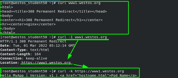
Test: when the external host accesses port 80, it will automatically redirect to port 443 of ingress
(5)ingress certification
Basic Authentication - NGINX Ingress Controllerhttps://kubernetes.github.io/ingress-nginx/examples/auth/basic/ Generate authentication files and import them into kubectl resources
#Install the tool httpd tools for generating authentication key
yum install -y httpd-tools
#Create an authenticated user
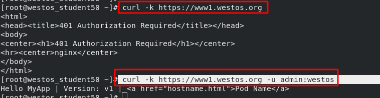
[root@server2 ingress]# htpasswd -c auth admin
New password: westos
Re-type new password: westos
Adding password for user admin
#Load the user authentication file into the kubectl resource
[root@server2 ingress]# kubectl create secret generic basic-auth --from-file=auth
#Check whether the user authentication pod resources are ready
[root@server2 ingress]# kubectl get secrets
NAME TYPE DATA AGE
basic-auth Opaque 1 20s
default-token-tcwmq kubernetes.io/service-account-token 3 7d21h
tls-secret kubernetes.io/tls 2 19m
In ingress Add user authentication options to yaml
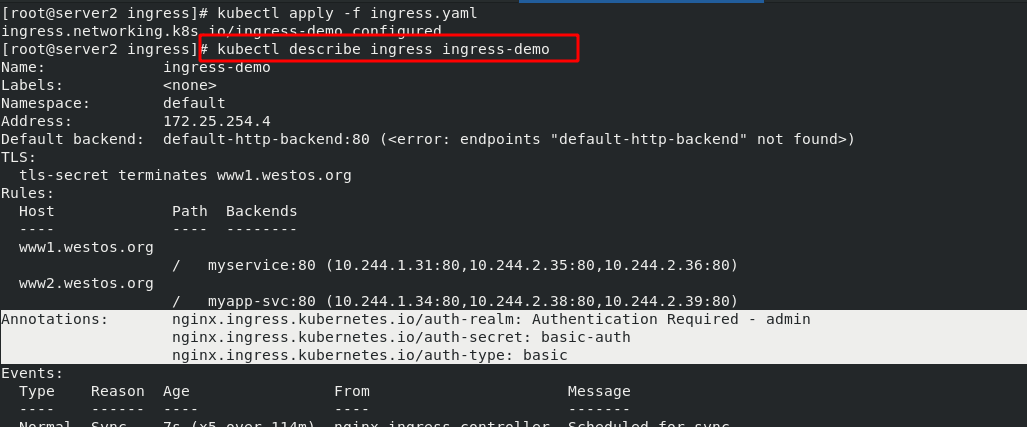
[root@server2 ingress]# vim ingress.yaml
  1 apiVersion: networking.k8s.io/v1
  2 kind: Ingress
  3 metadata:
  4   name: ingress-demo
  5   annotations:                #Add options for user authentication
  6     nginx.ingress.kubernetes.io/auth-type: basic
  7     nginx.ingress.kubernetes.io/auth-secret: basic-auth
  8     nginx.ingress.kubernetes.io/auth-realm: 'Authentication Required - admin'
  9 spec:
 10   tls:
 11   - hosts:
 12     - www1.westos.org
 13     secretName: tls-secret
 14   ingressClassName: nginx
 15   rules:
 16   - host: www1.westos.org
 17     http:
 18       paths:
 19       - path: /                         #Direct access to the root directory
 20         pathType: Prefix
 21         backend:                #Set the svc of the backend
 22           service:
 23             name: myservice             #The svc name of the backend must match
 24             port:
 25               number: 80
 26   - host: www2.westos.org
 27     http:
 28       paths:
 29       - path: /                         #Direct access to the root directory
 30         pathType: Prefix
 31         backend:                #Set the svc of the backend
 32           service:
 33             name: myapp-svc             #The svc name of the backend must match
 34             port:
 35               number: 80
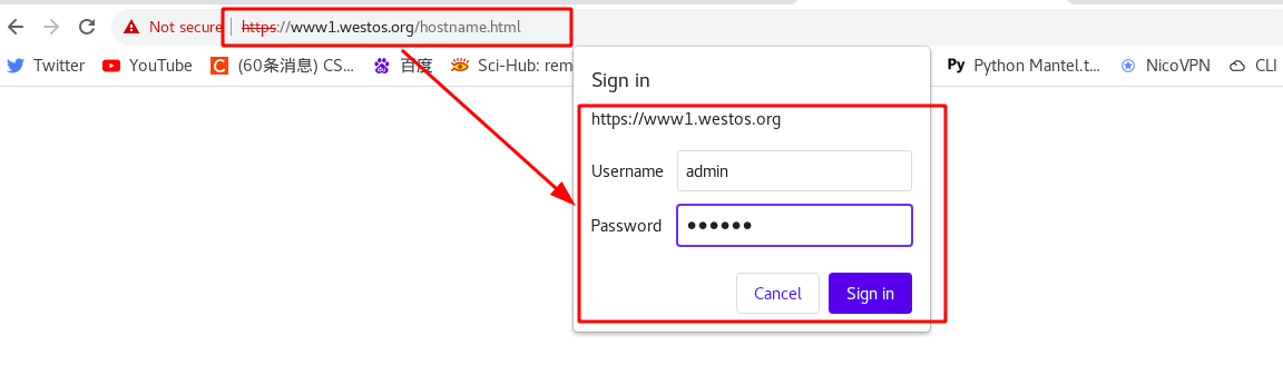
Rerun ingress After the yaml file, you can see the authentication information. This means that access to this domain name requires authentication.
Test:
(6)ingress redirection
Rewrite - NGINX Ingress Controllerhttps://kubernetes.github.io/ingress-nginx/examples/rewrite/
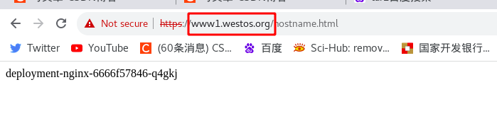
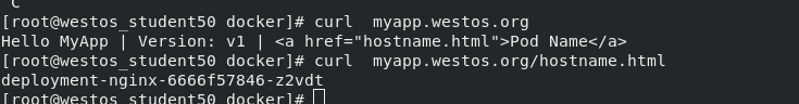
Requirement: direct redirect to "www1.westos.org.hostname.html" when visiting "www1.westos.org"
In ingress Add redirection statement in yaml file, with the format as follows:
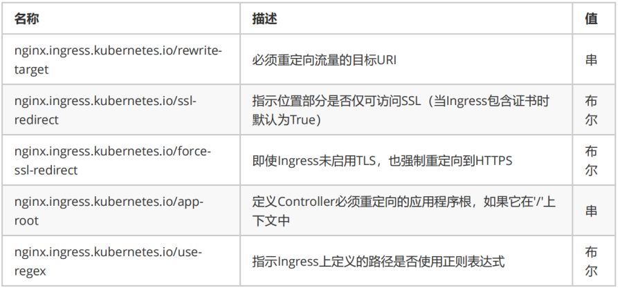
[root@server2 ingress]# vim ingress.yaml
  1 apiVersion: networking.k8s.io/v1
  2 kind: Ingress
  3 metadata:
  4   name: ingress-demo
  5   annotations:
  6     nginx.ingress.kubernetes.io/app-root: /hostname.html    #redirect
  ******
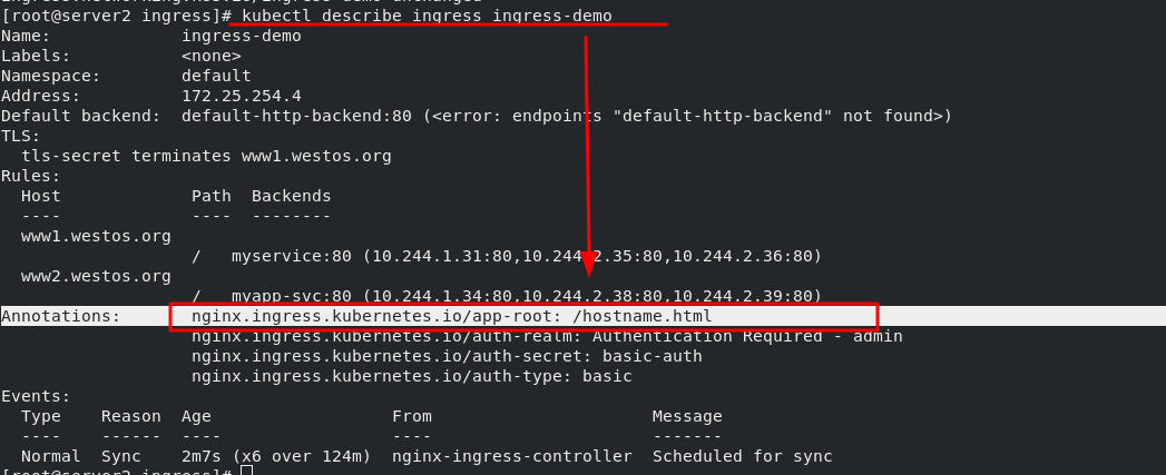
Test: after setting, test through the browser. When you enter "www1.westos.org", you will automatically redirect to "www1.westos.org/hostname.html"
10. Advanced features of ingress
annotations parameter:
Canary:
Annotations - NGINX Ingress Controllerhttps://kubernetes.github.io/ingress-nginx/user-guide/nginx-configuration/annotations/#canary Introduction to Canary:
 http://idcsec.com/2019/09/12/kubernetes%E5%9F%BA%E4%BA%8Enginx-ingress%E8%BF%9B%E8%A1%8C%E8%93%9D%E7%BB%BF%E9%83%A8%E7%BD%B2-%E9%87%91%E4%B8%9D%E9%9B%80%E5%8F%91%E5%B8%83canary/
Deploy version B after shutting down version A. this technology means that the downtime of the service depends on the shutdown and startup duration of the application. It has a great impact on users
kubernetes rolling update method:
The rolling update strategy includes gradually updating the version of the application by replacing instances one by one until all instances are updated. It usually follows the following process: use the version A pool behind the load balancer and deploy an instance of version B. When the service is ready to accept traffic, the instance is added to the pool. Then, remove an instance of version A from the pool and close it.
You can adjust the following parameters to increase deployment time:
maxSurge: how many instances to add in addition to the current number.
maxUnavailable: the number of unavailable instances in the rolling update process.

Blue green deployment:
Blue / Green deployment strategy: version B (green) is deployed together with version A (blue), and the number of instances is exactly the same. After testing that the new version meets all requirements, the traffic switches from version A to version B at the load balancer level

canary:
Canary deployment involves gradually transferring production traffic from version A to version B. generally, traffic is divided according to weight. For example, 90% of requests go to version A and 10% to version B

A / B test:
A / B test deployment includes routing a subset of users to new functions under specific conditions. It is often a technique for making business decisions based on statistics rather than deployment policies. This can be achieved by adding additional functionality for canary deployment
11. Canary publishing practice
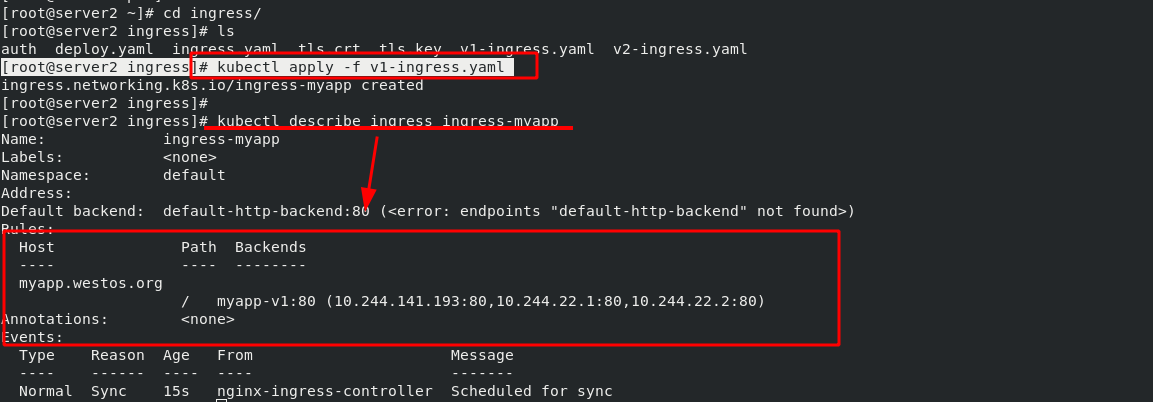
On the basis of previous experiments, the names of the two SVCS were changed to "myapp-v1" and "myapp-v2" respectively to simulate the two versions and view the iteration effect of the versions. (delete the previous ingress to prevent it from affecting this experiment)
The version of "myapp-v1" is as follows:
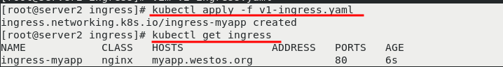
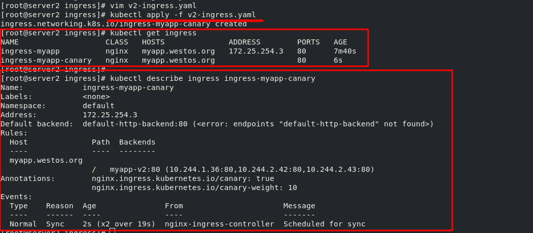
[root@server2 ingress]# vim v1-ingress.yaml
  1 apiVersion: networking.k8s.io/v1
  2 kind: Ingress
  3 metadata:
  4   name: ingress-myapp
  5 spec:
  6   ingressClassName: nginx
  7   rules:
  8   - host: myapp.westos.org
  9     http:
 10       paths:
 11       - path: /
 12         pathType: Prefix
 13         backend:
 14           service:
 15             name: myapp-v1
 16             port:
 17               number: 80
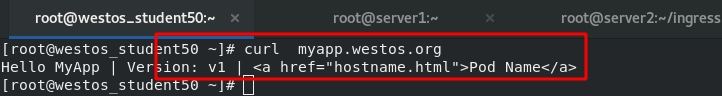
After making it effective, you can see that the current image version is "mapp-v1" when accessing the external host
If you need to update to the "myapp V2" version now, use the Canary method to slowly move the traffic of v1 to v2.
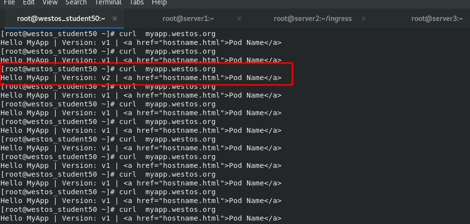
[root@server2 ingress]# vim v2-ingress.yaml
  1 apiVersion: networking.k8s.io/v1
  2 kind: Ingress
  3 metadata:
  4   name: ingress-myapp-canary
  5   annotations:
  6     nginx.ingress.kubernetes.io/canary: "true"        #Enable Canary mode
  7     nginx.ingress.kubernetes.io/canary-weight: "10"    #Transfer 10% of the flow first
  8 spec:
  9   ingressClassName: nginx
 10   rules:
 11   - host: myapp.westos.org
 12     http:
 13       paths:
 14       - path: /
 15         pathType: Prefix
 16         backend:
 17           service:
 18             name: myapp-v2
 19             port:
 20               number: 80
In the host test, about once every 10 accesses will be allocated to v2
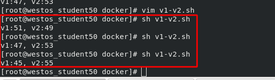
Next, adjust the traffic ratio to 50, which means that every 100 visits, 50 are allocated to v2. It is implemented in the host through a script, which is as follows:
[root@westos_student50 docker]# vim v1-v2.sh
  1 #!/bin/bash
  2
  3 v1=0
  4 v2=0
  5
  6 for (( i=0; i<100; i++))
  7 do
  8     response=`curl -s myapp.westos.org |grep -c v1`
  9
 10     v1=`expr $v1 + $response`
 11     v2=`expr $v2 + 1 - $response`
 12
 13 done
 14
 15 echo "v1:$v1, v2:$v2"
12. calico network plug-in
If you want to control the access of some services to the network in the cluster, you need to set corresponding network policies. Setting the network policy requires the support of the network plug-in.
The previously used "flannel network plug-in" cannot provide such a service, so it is necessary to replace the network plug-in "calico network plug-in" that can provide this service.
(1)calico network plug-in official website
(2)calico introduction:
flannel implements network communication, and calico's feature is the isolation between pod s.
Routing through BGP, but the topology calculation and convergence of large-scale endpoints often require a certain amount of time and computing resources.
Pure three-tier forwarding, without any NAT and overlay in the middle, has the best forwarding efficiency.
Calico only relies on three-tier routing. Calico's less dependency makes it suitable for all VM, Container, white box or mixed environment scenarios.
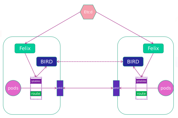
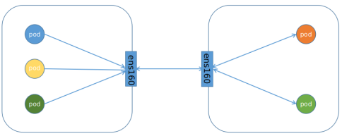
(3)calico network architecture
Felix: monitor the storage acquisition events in the ECTD center. After the user creates a pod, Felix is responsible for setting its network card, IP and MAC, and then write a note in the routing table of the kernel, indicating that this IP should go to this network card. Similarly, if the user makes an isolation policy, Felix will also create the policy into the ACL to achieve isolation.
BIRD: a standard routing program. It will get which IP's routing has changed from the kernel, and then spread to other host computers through the standard BGP routing protocol to let the outside world know that this IP is here and come here when routing.
(4)calico working mode
IPIP working mode: it is applicable to the scenario where pod s accessing each other are not in the same network segment and are accessed across network segments.
BGP working mode: it is applicable to pod s accessing each other in the same network segment, and it is applicable to large networks.
(5)calico installation and deployment
#Download calico Yaml file
curl https://projectcalico.docs.tigera.io/manifests/calico.yaml -O calico.yaml
#Change calico The image source in yaml is the name of the local image warehouse
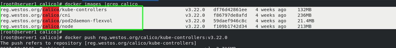
[root@server2 calico]# cat calico.yaml |grep image
image: calico/cni:v3.22.0
image: calico/cni:v3.22.0
image: calico/pod2daemon-flexvol:v3.22.0
image: calico/node:v3.22.0
image: calico/kube-controllers:v3.22.0
calico. Several images involved in yaml files have been packaged and placed in the local warehouse.
#Clear the previous flannel component in server2
[root@server2 ~]# kubectl delete -f kube-flannel.yml

#Delete redundant configuration files in each node
[root@server2 net.d]# rm -f /etc/cni/net.d/10-flannel.conflist

#Run calico YML file and check whether each node is ready
[root@server2 calico]# kubectl apply -f calico.yaml
[root@server2 calico]# kubectl get pod -n kube-system
    NAME                                       READY   STATUS    RESTARTS     AGE
    calico-kube-controllers-599bb85f6d-pkzzv   1/1     Running   0            80s
    calico-node-7r29t                          1/1     Running   0            80s
    calico-node-fn49q                          0/1     Running   0            80s
    calico-node-qf6t2                          0/1     Running   0            80s
In order not to be disturbed by previous experiments, delete all previous pod s
  579  kubectl delete -f v1-ingress.yaml
  580  kubectl delete -f v2-ingress.yaml
  581  kubectl delete svc --all
  582  kubectl delete deployments.apps deployment-myapp
  583  kubectl delete deployments.apps deployment-nginx
Then create a new project. And there is no problem testing in the cluster.
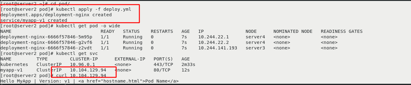
To access from outside the cluster, you also need an ingress, so start the previous "V1 ingress. Yaml"
Test: access the internal cluster on the external host and it can be accessed normally. Therefore, calico has been installed
(6)calico network policy
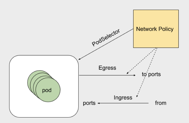
NetworkPolicy policy policy model: network inbound and outbound rules that control pod s in a namespace
calico network policy official document:
Declare network policy | Kubernetes this article can help you start using Kubernetes' NetworkPolicy API to declare network policy to manage the communication between pods. Note: this section links to the third-party project that provides the functions required by Kubernetes. The authors of the Kubernetes project are not responsible for these projects. This page follows the CNCF website guide and lists items alphabetically. To add items to this list, read the content guide before committing changes. To start, you must have a Kubernetes cluster, and your Kubernetes cluster must have kubectl command line tool. It is recommended that you run this tutorial on a cluster with at least two nodes that do not host the control plane. If you don't have a cluster yet, you can build your own cluster through Minikube, or you can use any of the following Kubernetes tools: Katacoda plays with Kubernetes. Your Kubernetes server version must be no less than version v1 8. For version information, enter kubectl version You first need to have a Kubernetes cluster that supports network policy. There are already many network providers supporting NetworkPolicy, including: antrea calico cilium Kube router Romana weave network, create an nginx Deployment and expose it through services to see how Kubernetes network policy works, Kubectl create Deployment nginx -- Image = nginx Deployment Apps / nginx created exposes this Deployment as a Service named nginx:https://kubernetes.io/zh/docs/tasks/administer-cluster/declare-network-policy/Kubernetespod is allowed to communicate with various network "entities" (we use the word "entity" here to avoid overloading the more common terms such as "endpoints" and "services", which have specific Kubernetes notifications) over the network-- If you want to control network traffic at the IP address or port level (OSI layer 3 or 4), you can consider using Kubernetes network policy for specific applications in the cluster. NetworkPolicy is an application-centered structure that allows you to set how to allow pod to communicate with various network "entities" on the network (we use entities here to avoid overusing common terms such as "endpoint" and "service", which have a specific meaning in Kubernetes). The pod that the pod can communicate with is identified by the combination of the following three identifiers: other allowed Pods (exception: the pod cannot block access to itself) allowed namespace IP blocks (exception: communication with the node where the pod runs is always allowed, regardless of the pod or the IP address of the node) selector to specify what traffic is allowed to and from the Pod(s) that match the selector.https://kubernetes.io/zh/docs/concepts/services-networking/network-policies/
Experiment 1 - set calico network policy, the contents are as follows:
[root@server2 calico]# vim policy.yaml
  1 apiVersion: networking.k8s.io/v1
  2 kind: NetworkPolicy
  3 metadata:
  4   name: access-nginx
  5 spec:
  6   podSelector:
  7     matchLabels:
  8       app: nginx                #Restrictions are only made for nginx tags
  9   ingress:                        #Inbound requests can only be accessed through a pod with this tag
 10   - from:
 11     - podSelector:
 12         matchLabels:
 13           access: "true"
policy. After the yaml file policy takes effect, it is only valid for the pod labeled "app=nginx".
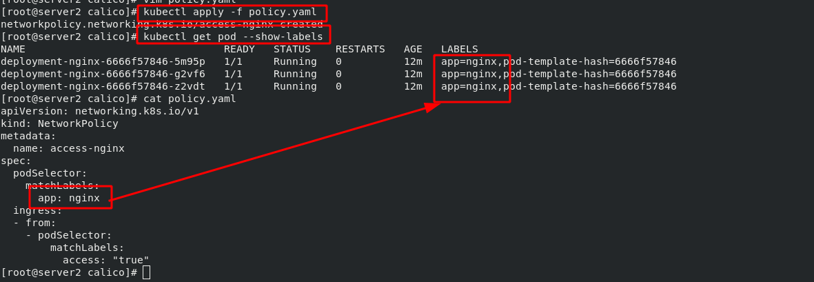
Since the network policy is set to "inbound requests can only be accessed through the pod with this tag", and the pod tag of the request is not "nginx", the pod cannot be accessed in the cluster
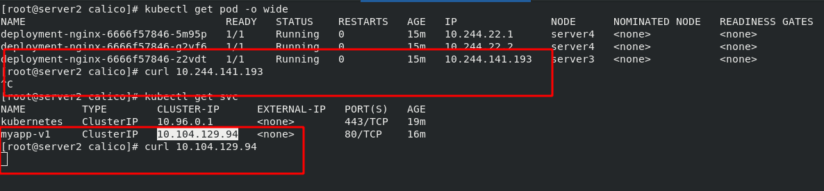
Through other image tests, you can see that the newly created busyboxplus image is labeled "demo", so you still can't access the inside of the pod.
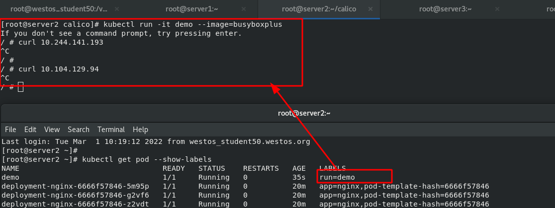
Connect server2 to another terminal and change the label of demo to "access=true". Once you have this tag, you can access it from busyboxplus again to access the inside of the pod.
#Change the label of the demo
[root@server2 ~]# kubectl label pod demo access=true
pod/demo labeled
#View the label of the demo
[root@server2 ~]# kubectl get pod --show-labels
NAME                                READY   STATUS    RESTARTS   AGE   LABELS
demo                                1/1     Running   0          51s   access=true,run=demo
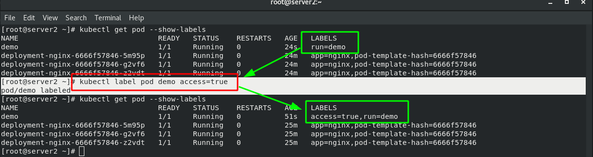
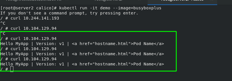
Experiment 2 - set calico network policy, the contents are as follows:
Indicates that the request with the matching pod tag of "access=true" can be accessed; Or restrict the access of "test" pods from the namespace
[root@server2 calico]# vim policy.yaml
  1 apiVersion: networking.k8s.io/v1
  2 kind: NetworkPolicy
  3 metadata:
  4   name: access-nginx
  5 spec:
  6   podSelector:
  7     matchLabels:
  8       app: nginx
  9   ingress:
 10   - from:
 11     - podSelector:                #Strategy 1
 12         matchLabels:
 13           access: "true"
 14     - namespaceSelector:            #Strategy 2
 15         matchLabels:
 16           role: "test"
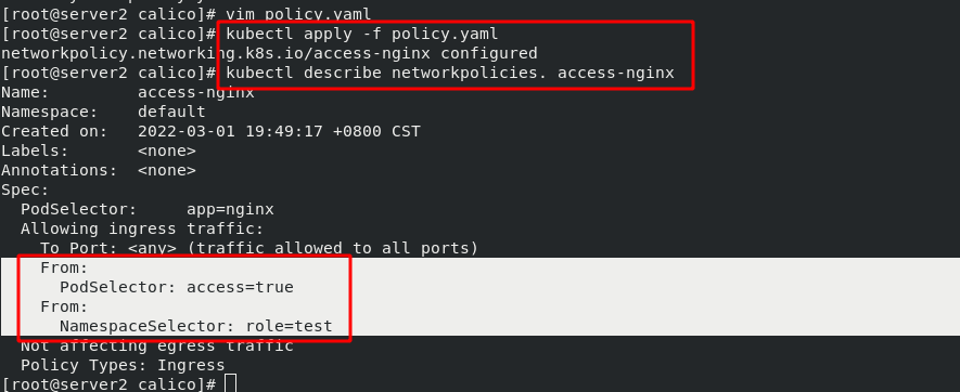
Create a new test namespace, but its label is still the default
#Create a namespace named test
[root@server2 calico]# kubectl create namespace test
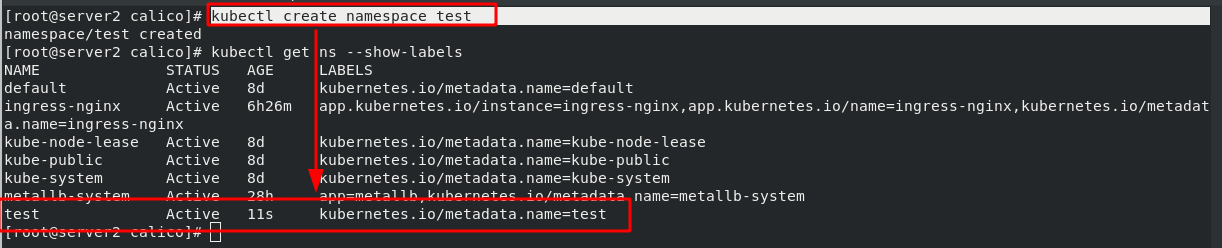
Rerun the previous demo. The namespace of this run is on test. Test in busyboxplus, unable to access internal pod.
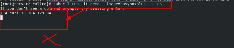
#Label the namespace of test
[root@server2 calico]# kubectl label ns test role=test
namespace/test labeled


[root@server2 calico]# kubectl get ns --show-labels
test              Active   5m30s   kubernetes.io/metadata.name=test,role=test
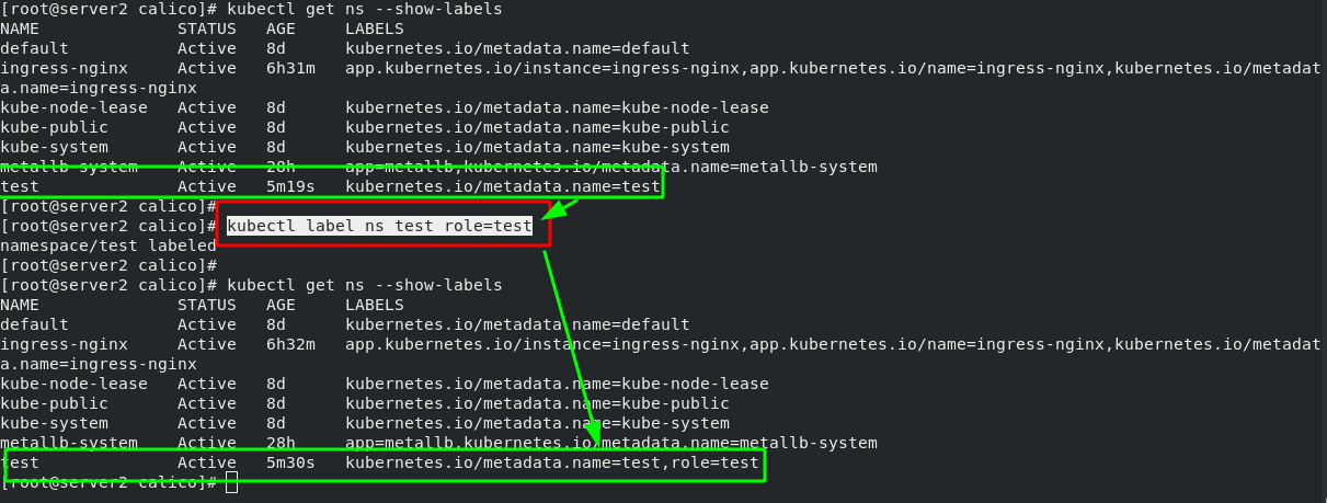
After testing again, you can see that you are allowed to access the pod normally.
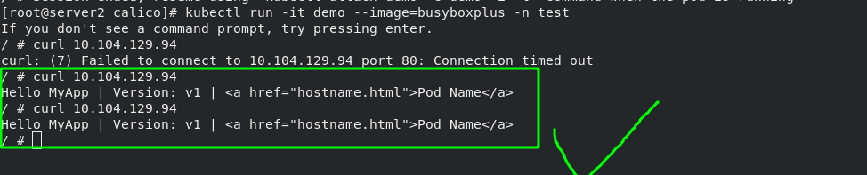
Note: when writing multiple policies, there is a big difference between adding "-" and not adding "-" indicates or, and one condition can be met; Do not add "-" and all conditions must be met at the same time.
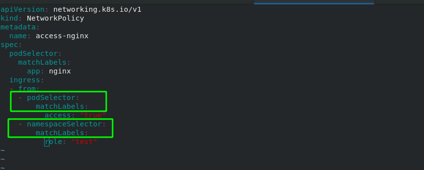
9, kubectl command Guide
kubectl command Guide:
Kubectl Reference Docshttps://kubernetes.io/docs/reference/generated/kubectl/kubectl-commands
#Import local image package
docker load -i base-debian10.tar (Image name)


Master View status:
kubectl get cs
kubectl get node
kubectl get pod -n kube-system -o wide

#Create pod
[root@server2]# kubectl apply -f demo.yml
#Delete pod (two methods)
[root@server2]# kubectl delete -f demo.yml
[root@server2]# kubectl delete pod liveness-http

#View the specific information of pod
kubectl get pod -n kube-system -o wide          #Displays all pod s in the Kube system domain
kubectl describe pod nginx                 #Display the pod information named nginx. If you do not add - n, it means you can view it in the default namespace

kubectl logs nginx -n kube-system            #Display nginx log, - n: specify namespace as Kube system

kubectl logs nginx -c init-container            #Display the log of init container container under pod named nginx

#View all namespace s
[root@server2 ~]# kubectl get ns
NAME              STATUS   AGE
default           Active   3d4h
kube-node-lease   Active   3d4h
kube-public       Active   3d4h
kube-system       Active   3d4h
#Specify namespace
[root@server2 ~]# kubectl get pod -n kube-system
NAME                              READY   STATUS    RESTARTS      AGE
coredns-7b56f6bc55-6httc          1/1     Running   1 (28m ago)   3d4h
coredns-7b56f6bc55-k5fnm          1/1     Running   1 (28m ago)   3d4h

#Create container manually
kubectl run -it demo --image=busybox --restart=Never        #-it, interactive

#View the tag of pod
[root@server2 init]# kubectl get pod --show-labels
NAME            READY   STATUS    RESTARTS   AGE   LABELS
liveness-http   0/1     Running   0          64m   test=liveness

#Enter the inside of pod and operate through bash
[root@server2 init]# kubectl exec -it liveness-http  -- bash        #Liveness HTTP is the pod name

#Show pod tag
[root@server2 pod]# kubectl get pod --show-labels
NAME                       READY   STATUS    RESTARTS   AGE     LABELS
replicaset-example-8lwkf   1/1     Running   0          3m50s   app=nginx
replicaset-example-hdgc8   1/1     Running   0          3m50s   app=nginx
replicaset-example-w4zpt   1/1     Running   0          3m50s   app=nginx

#Change the above pod tag
[root@server2 pod]# kubectl label pod replicaset-example-8lwkf app=myapp --overwrite