preface
This program design is based on embedded development board CT117E,stm32f103RBT6. If you don't understand the code of which module, you can click my blog to see the writing ideas of each module.
1, Test questions
2, Modules needed
1.LED
The code is as follows: LED c:
#include "led.h"

void led_init(void)
{
  GPIO_InitTypeDef GPIO_InitStructure;

  RCC_APB2PeriphClockCmd(RCC_APB2Periph_GPIOD | RCC_APB2Periph_GPIOC, ENABLE);

  /* Configure PD0 and PD2 in output pushpull mode */
  GPIO_InitStructure.GPIO_Pin = GPIO_Pin_2;
  GPIO_InitStructure.GPIO_Speed = GPIO_Speed_50MHz;
  GPIO_InitStructure.GPIO_Mode = GPIO_Mode_Out_PP;
  GPIO_Init(GPIOD, &GPIO_InitStructure);

   GPIO_InitStructure.GPIO_Pin = 0xff00;
   GPIO_Init(GPIOC, &GPIO_InitStructure);
   GPIOC->ODR |=0xff<<8;
   GPIOD->ODR |=1<<2;
   GPIOD->ODR &=~(1<<2);
}

void led_ctrl(u8 ledx,u8 status)   //Control led on and off, ledx value range: 8-15
{
	if(status)
	{
		GPIOC->ODR &=~(1<<ledx);
   		GPIOD->ODR |=1<<2;
   		GPIOD->ODR &=~(1<<2);
	}
	else
	{
	  	GPIOC->ODR |=1<<ledx;
   		GPIOD->ODR |=1<<2;
   		GPIOD->ODR &=~(1<<2);
	}
}
led.h:
#ifndef LED_H
#define LED_H

#include "stm32f10x.h"

void led_init(void);
void led_ctrl(u8 ledx,u8 status);
#endif
2. Key
The code is as follows: key c:
#include "key.h"

void key_init(void)
{
  GPIO_InitTypeDef GPIO_InitStructure;

  RCC_APB2PeriphClockCmd(RCC_APB2Periph_GPIOA | RCC_APB2Periph_GPIOB, ENABLE);

  /* Configure PD0 and PD2 in output pushpull mode */
  GPIO_InitStructure.GPIO_Pin = GPIO_Pin_0 | GPIO_Pin_8;
  GPIO_InitStructure.GPIO_Mode = GPIO_Mode_IN_FLOATING;
  GPIO_Init(GPIOA, &GPIO_InitStructure);

  GPIO_InitStructure.GPIO_Pin = GPIO_Pin_1 | GPIO_Pin_2;
  GPIO_Init(GPIOB, &GPIO_InitStructure);

}
key.h:
#include "key.h"

#ifndef KEY_H
#define KEY_H

#include "stm32f10x.h"

#define key1 GPIO_ReadInputDataBit(GPIOA,GPIO_Pin_0) / / read the status of the key
#define key2 GPIO_ReadInputDataBit(GPIOA,GPIO_Pin_8)
#define key3 GPIO_ReadInputDataBit(GPIOB,GPIO_Pin_1)
#define key4 GPIO_ReadInputDataBit(GPIOB,GPIO_Pin_8)

void key_init(void);
#endif
3.ADC
The code is as follows: ADC c:
#include "adc.h"

void adc_init(void)
{
  ADC_InitTypeDef ADC_InitStructure;
  GPIO_InitTypeDef GPIO_InitStructure;
  RCC_ADCCLKConfig(RCC_PCLK2_Div6);
  /* Enable ADC1, ADC2 and GPIOC clock */
  RCC_APB2PeriphClockCmd(RCC_APB2Periph_ADC1 | RCC_APB2Periph_GPIOB, ENABLE);
  /* Configure PC.01, PC.02 and PC.04 (ADC Channel11, Channel12 and Channel14)
    as analog input ----------------------------------------------------------*/
  GPIO_InitStructure.GPIO_Pin = GPIO_Pin_0;
  GPIO_InitStructure.GPIO_Mode = GPIO_Mode_AIN;
  GPIO_Init(GPIOB, &GPIO_InitStructure);

  ADC_InitStructure.ADC_Mode = ADC_Mode_Independent;
  ADC_InitStructure.ADC_ScanConvMode = ENABLE;
  ADC_InitStructure.ADC_ContinuousConvMode = ENABLE;
  ADC_InitStructure.ADC_ExternalTrigConv = ADC_ExternalTrigConv_None;
  ADC_InitStructure.ADC_DataAlign = ADC_DataAlign_Right;
  ADC_InitStructure.ADC_NbrOfChannel = 1;
  ADC_Init(ADC1, &ADC_InitStructure);
  /* ADC2 regular channels configuration */
  ADC_RegularChannelConfig(ADC1, ADC_Channel_8, 1, ADC_SampleTime_239Cycles5);

  ADC_Cmd(ADC1, ENABLE);

  /* Enable ADC1 reset calibration register */
  ADC_ResetCalibration(ADC1);
  /* Check the end of ADC1 reset calibration register */
  while(ADC_GetResetCalibrationStatus(ADC1));

  /* Start ADC1 calibration */
  ADC_StartCalibration(ADC1);
  /* Check the end of ADC1 calibration */
  while(ADC_GetCalibrationStatus(ADC1));
}


u16 get_adc(void)     //Simple filtering, averaging and obtaining 12 bit adc value
{
	int i;
	u16 adc_buff[10];
	ADC_SoftwareStartConvCmd(ADC1, ENABLE);
	for(i=0;i<10;i++)
	{
		 adc_buff[i]=ADC_GetConversionValue(ADC1);
	}
	for(i=1;i<10;i++)
	{
		adc_buff[0] += adc_buff[i];
	}
	ADC_SoftwareStartConvCmd(ADC1, DISABLE);
	return adc_buff[0]/10;


}
adc.h:
#ifndef ADC_H
#define ADC_H

#include "stm32f10x.h"

void adc_init(void);
u16 get_adc(void);

#endif
4. Timer 3 generates pwm
The code is as follows: PWM c:
#include "pwm.h"
u32 CH1_VAL,CH1_DUTY,CH2_VAL,CH2_DUTY;
void pwm_time3_init(void)
{
   TIM_TimeBaseInitTypeDef  TIM_TimeBaseStructure;
   TIM_OCInitTypeDef  TIM_OCInitStructure;
   GPIO_InitTypeDef GPIO_InitStructure;
   NVIC_InitTypeDef NVIC_InitStructure;

   RCC_APB1PeriphClockCmd(RCC_APB1Periph_TIM3, ENABLE);

  /* GPIOA clock enable */
  RCC_APB2PeriphClockCmd(RCC_APB2Periph_GPIOA, ENABLE);
  /* Enable the TIM3 global Interrupt */
  NVIC_InitStructure.NVIC_IRQChannel = TIM3_IRQn;
  NVIC_InitStructure.NVIC_IRQChannelPreemptionPriority = 0;
  NVIC_InitStructure.NVIC_IRQChannelSubPriority = 0;
  NVIC_InitStructure.NVIC_IRQChannelCmd = ENABLE;
  NVIC_Init(&NVIC_InitStructure);

   GPIO_InitStructure.GPIO_Pin =  GPIO_Pin_6 | GPIO_Pin_7 ;
   GPIO_InitStructure.GPIO_Mode = GPIO_Mode_AF_PP;
   GPIO_InitStructure.GPIO_Speed = GPIO_Speed_50MHz;

   GPIO_Init(GPIOA, &GPIO_InitStructure);

  TIM_TimeBaseStructure.TIM_Period = 65535;
  TIM_TimeBaseStructure.TIM_Prescaler = 71;
  TIM_TimeBaseStructure.TIM_ClockDivision = 0;
  TIM_TimeBaseStructure.TIM_CounterMode = TIM_CounterMode_Up;

  TIM_TimeBaseInit(TIM3, &TIM_TimeBaseStructure);

  /* Output Compare Toggle Mode configuration: Channel1 */
  TIM_OCInitStructure.TIM_OCMode = TIM_OCMode_Toggle;
  TIM_OCInitStructure.TIM_OutputState = TIM_OutputState_Enable;
  TIM_OCInitStructure.TIM_Pulse = 65534;
  TIM_OCInitStructure.TIM_OCPolarity = TIM_OCPolarity_Low;
  TIM_OC1Init(TIM3, &TIM_OCInitStructure);
  TIM_OC2Init(TIM3, &TIM_OCInitStructure);

  TIM_Cmd(TIM3, ENABLE);

  /* TIM IT enable */
  TIM_ITConfig(TIM3, TIM_IT_CC1 | TIM_IT_CC2 , ENABLE);

}
void set_pwm(u32 ch1_val,u32 ch1_duty,u32 ch2_val,u32 ch2_duty)
{
	CH1_VAL=1000000/ch1_val;
	CH2_VAL=1000000/ch2_val;

	CH1_DUTY=CH1_VAL*ch1_duty/100;
	CH2_DUTY=CH2_VAL*ch2_duty/100;

	TIM_SetCounter(TIM3,0);
	TIM_SetCompare1(TIM3,0);
	TIM_SetCompare2(TIM3,0);
}
u32 capture;
u8 ch1_flag=0;
u8 ch2_flag=0;
void TIM3_IRQHandler(void)
{
  /* TIM3_CH1 toggling with frequency = 183.1 Hz */
  if (TIM_GetITStatus(TIM3, TIM_IT_CC1) != RESET)
  {
    TIM_ClearITPendingBit(TIM3, TIM_IT_CC1 );
    capture = TIM_GetCapture1(TIM3);
	if(ch1_flag)
	{
		TIM_SetCompare1(TIM3, capture + CH1_DUTY );
	}
    else
	{
		TIM_SetCompare1(TIM3, capture + CH1_VAL - CH1_DUTY );
	}
	ch1_flag ^=1;
  }

  /* TIM3_CH2 toggling with frequency = 366.2 Hz */
  if (TIM_GetITStatus(TIM3, TIM_IT_CC2) != RESET)
  {
    TIM_ClearITPendingBit(TIM3, TIM_IT_CC2);
    capture = TIM_GetCapture2(TIM3);
	if(ch2_flag)
	{
		TIM_SetCompare2(TIM3, capture + CH2_DUTY);
	}
	else
	{
		TIM_SetCompare2(TIM3, capture + CH2_VAL - CH2_DUTY );
	}
	ch2_flag ^=1;

  }


}
pwm.h:
#ifndef PWM_H
#define PWM_H
#include "stm32f10x.h"

void pwm_time3_init(void);
void set_pwm(u32 ch1_val,u32 ch1_duty,u32 ch2_val,u32 ch2_duty);

#endif
5. Timer 2 captures PWM (not required)
(there is no tool to measure pwm on hand. Write the capture program with timer 2 to capture and observe to verify the correctness of the program)
The code is as follows: capture c:
#include "capture.h"

void capture_time2_init(void)
{
	TIM_ICInitTypeDef  TIM_ICInitStructure;
	TIM_TimeBaseInitTypeDef  TIM_TimeBaseStructure;
	GPIO_InitTypeDef GPIO_InitStructure;
    NVIC_InitTypeDef NVIC_InitStructure;

	RCC_APB1PeriphClockCmd(RCC_APB1Periph_TIM2, ENABLE);
	  /* GPIOA clock enable */
    RCC_APB2PeriphClockCmd(RCC_APB2Periph_GPIOA , ENABLE);

	NVIC_InitStructure.NVIC_IRQChannel = TIM2_IRQn;
    NVIC_InitStructure.NVIC_IRQChannelPreemptionPriority = 0;
    NVIC_InitStructure.NVIC_IRQChannelSubPriority = 0;
    NVIC_InitStructure.NVIC_IRQChannelCmd = ENABLE;
    NVIC_Init(&NVIC_InitStructure);

	GPIO_InitStructure.GPIO_Pin =  GPIO_Pin_1 ;
    GPIO_InitStructure.GPIO_Mode = GPIO_Mode_IPU;

    GPIO_Init(GPIOA, &GPIO_InitStructure);

	 /* Time base configuration */
  TIM_TimeBaseStructure.TIM_Period = 65535;
  TIM_TimeBaseStructure.TIM_Prescaler = 71;
  TIM_TimeBaseStructure.TIM_ClockDivision = 0;
  TIM_TimeBaseStructure.TIM_CounterMode = TIM_CounterMode_Up;

  TIM_TimeBaseInit(TIM2, &TIM_TimeBaseStructure);

  TIM_ICInitStructure.TIM_Channel = TIM_Channel_2;
  TIM_ICInitStructure.TIM_ICPolarity = TIM_ICPolarity_Rising;
  TIM_ICInitStructure.TIM_ICSelection = TIM_ICSelection_DirectTI;
  TIM_ICInitStructure.TIM_ICPrescaler = TIM_ICPSC_DIV1;
  TIM_ICInitStructure.TIM_ICFilter = 0x0;

  TIM_ICInit(TIM2, &TIM_ICInitStructure);
  TIM_Cmd(TIM2, ENABLE);

  /* Enable the CC2 Interrupt Request */
  TIM_ITConfig(TIM2, TIM_IT_CC2, ENABLE);

}
u8 ch2_mode=0;
u32 capture_val,capture_duty;
void TIM2_IRQHandler(void)
{
  if(TIM_GetITStatus(TIM2, TIM_IT_CC2) == SET)
  {
		TIM_ClearITPendingBit(TIM2, TIM_IT_CC2);
		switch(ch2_mode)
		{
			case 0: capture_val=0;
					capture_duty=0;
					TIM_SetCounter (TIM2,0);
					TIM_OC2PolarityConfig (TIM2,TIM_OCPolarity_Low);
					ch2_mode=1;
					break;

			case 1: capture_duty=TIM_GetCounter (TIM2);
					TIM_OC2PolarityConfig (TIM2,TIM_OCPolarity_High);
					ch2_mode=2;
					break;

			case 2: capture_val=TIM_GetCounter (TIM2);
					TIM_OC2PolarityConfig (TIM2,TIM_OCPolarity_High);
					ch2_mode=3;
					break;


			default :break;
		}
  }

}
capture.h:
#ifndef CAPTURE_H
#define CAPTURE_H

#include "stm32f10x.h"
extern u8 ch2_mode;
extern u32 capture_val,capture_duty;
void capture_time2_init(void);

#endif
3, Main function logic design
Idea flow chart:
stm32f10x_it.c:
#include "stm32f10x_it.h"
#include "pwm.h"
extern u32 TimingDelay;
extern u8 key_flag;
extern u8 a6;
extern u8 a7;
extern u16 pwm_num;

void SysTick_Handler(void)
{
	static u8 key_num=0;
	TimingDelay--;
	key_num++;
	pwm_num--;
	if(pwm_num==0)
	{
		set_pwm(100,a6,200,a7);		   //Update the parameters of pwm wave every 500ms, that is, 0.5 seconds. The problem requires a response of less than 1 second
		pwm_num=500;
	}
	if(key_num==50)
	{
		key_flag=1;
		key_num=0;
	}
}
main.c:
#include "stm32f10x.h"
#include "stdio.h"
#include "lcd.h"
#include "led.h"
#include "key.h"
#include "adc.h"
#include "pwm.h"
#include "capture.h"
u32 TimingDelay = 0;
u8 key_flag; //50ms key scanning mark
u8 key1_num; //The count value of key 1 is used to judge long press and short press. This test question is not used at present
u8 key2_num; //The count value of key 2 is used to judge long press and short press. This test question is not used at present
u8 key3_num; //The count value of key 3 is used to judge long press and short press. This test question is not used at present
u8 key4_num; //The count value of key 4 is used to judge long press and short press. This test question is not used at present
u8 key1_flag=1; //Mark 1 pressed by key 1: display data interface 0: display parameter interface
u8 key4_flag=1; //Flag pressed by key 4 1: automatic mode 0: manual mode
u8 a6=10; //PA6 duty cycle, range: 1-100
u8 a7=10; //PA7 duty cycle, range: 1-100
float adc_val; //Get the 12 data value of adc
u8 buff[20]; //Used to copy data for display
u16 pwm_num=500; //The duty cycle of pwm is modified again in the timer to achieve the effect of time-sharing multiplexing
void Delay_Ms(u32 nTime);
void key_read(void); //Key scan function
void led_show(void); //Display function
//Main Body
int main(void)
{
SysTick_Config(SystemCoreClock/1000);
Delay_Ms(200);
STM3210B_LCD_Init();
LCD_Clear(Black);
LCD_SetBackColor(Black);
LCD_SetTextColor(White);
led_init();
led_ctrl(8,1);
key_init();
adc_init();
pwm_time3_init();
set_pwm(100,a6,200,a7); //Initialize pwm wave
capture_time2_init();
while(1)
{
if(key_flag)
{
key_read();
adc_val=get_adc();
key_flag=0;
if(key4_flag)
{
a6=adc_val/0xfff*100; //The duty cycle is the voltage value of adc / 3.3, that is, the 12 bit data value divided by 0xfff
a7=adc_val/0xfff*100;
}
}
if(ch2_mode==3) //There is no requirement for this test question. Here is the pwm capture program written to verify whether my program is correct
{
sprintf((char *)buff," VAL:%d ",1000000/capture_val);
LCD_DisplayStringLine(Line7,buff);
sprintf((char *)buff," DUTY:%d ",capture_duty*100/capture_val);
LCD_DisplayStringLine(Line8,buff);
ch2_mode=0;
}
led_show(); //Interface display
}
}
//
void Delay_Ms(u32 nTime)
{
TimingDelay = nTime;
while(TimingDelay != 0);
}
void key_read(void)
{
if(key1==0) //Key 1
{
key1_num++;
if(key1_num==20) Press and hold the key for 1 second,There are no requirements for the test questions, so there is no execution code here
{
}
}
else
{
if(key1_num>1 && key1_num<10) //Short press
{
key1_flag ^=1; //The pressed flag bit of key 1 is reversed 1: data display interface 0: parameter display interface
}
key1_num=0;
}
if(key2==0 && key1_flag==0) //Key 2 is only valid in the parameter display interface
{
key2_num++;
if(key2_num==20)
{
}
}
else
{
if(key2_num>1 && key2_num<10)
{
if(key4_flag==0) //Parameter increment 10 is only valid in manual mode
{
a6=a6+10;
if(a6==100 || a6>90) //Parameter setting range 10-100
{
a6=10;
}
}
}
key2_num=0;
}
if(key3==0 && key1_flag==0) //Same as key 2
{
key3_num++;
if(key3_num==20)
{
}
}
else
{
if(key3_num>1 && key3_num<10)
{
if(key4_flag==0)
{
a7=a7+10;
if(a7==100 || a7>90)
{
a7=10;
}
}
}
key3_num=0;
}
if(key4==0)
{
key4_num++;
if(key4_num==20)
{
}
}
else
{
if(key4_num>1 && key4_num<10) //Key 4
{
key4_flag ^=1; //The flag bit pressed by key 4 is reversed 1: automatic mode 0: manual mode
if(key4_flag) //The light is on only in manual mode
{
led_ctrl(8,1);
}
else
{
led_ctrl(8,0);
}
}
key4_num=0;
}
}
void led_show(void)
{
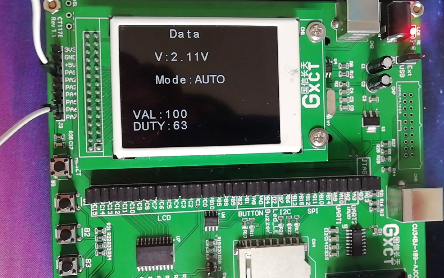
if(key1_flag) //Flag bit 1 of key 1: data interface 0: parameter interface
{
led_ctrl(9,1); //Data mode on led2
LCD_DisplayStringLine(Line0," Data");
sprintf((char *)buff," V:%0.2fV ",adc_val/0xfff*3.3);
LCD_DisplayStringLine(Line2,buff);
if(key4_flag) //Key 4 flag bit 1: automatic mode 0: manual mode
{
LCD_DisplayStringLine(Line4," Mode:AUTO ");
}
else
{
LCD_DisplayStringLine(Line4," Mode:MANU ");
}
}
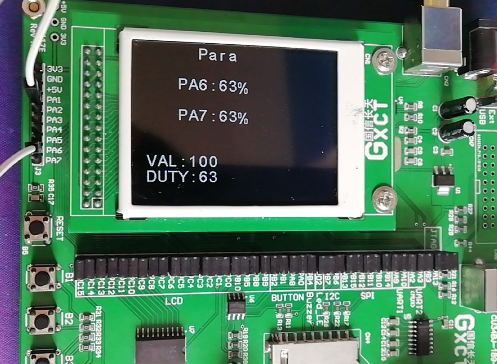
else //Display of parameter interface
{
led_ctrl(9,0);
LCD_DisplayStringLine(Line0," Para");
sprintf((char *)buff," PA6:%d%% ",a6);
LCD_DisplayStringLine(Line2,buff);
sprintf((char *)buff," PA7:%d%% ",a7);
LCD_DisplayStringLine(Line4,buff);
}
}
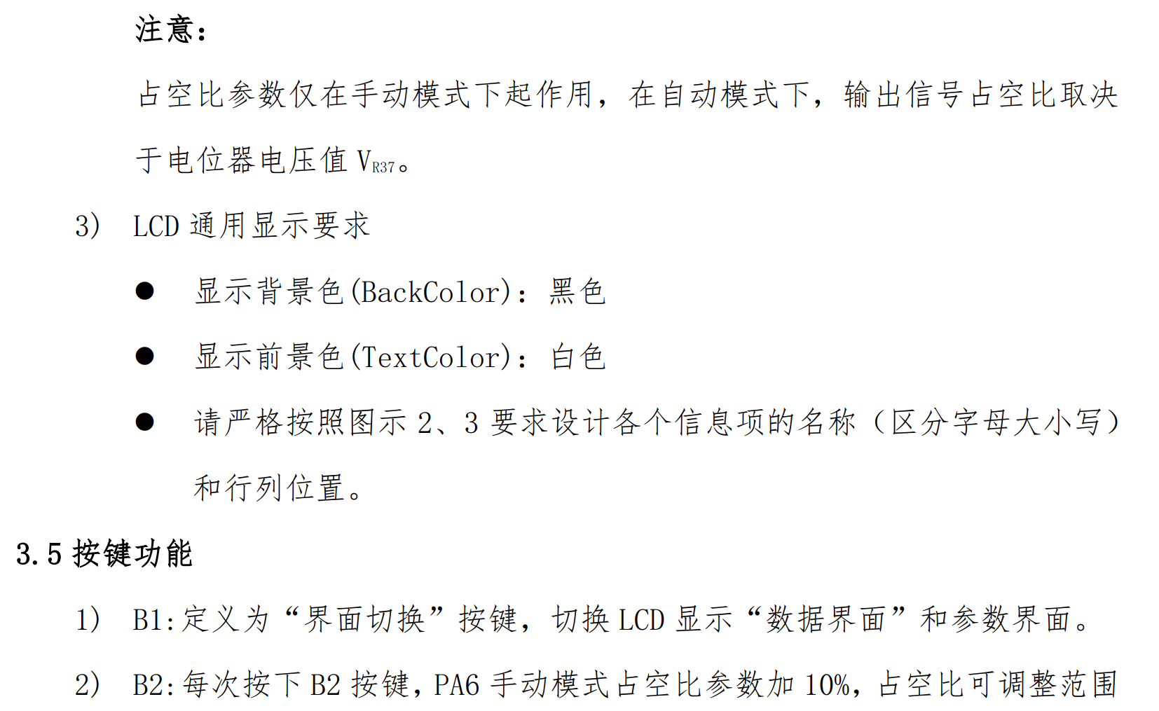
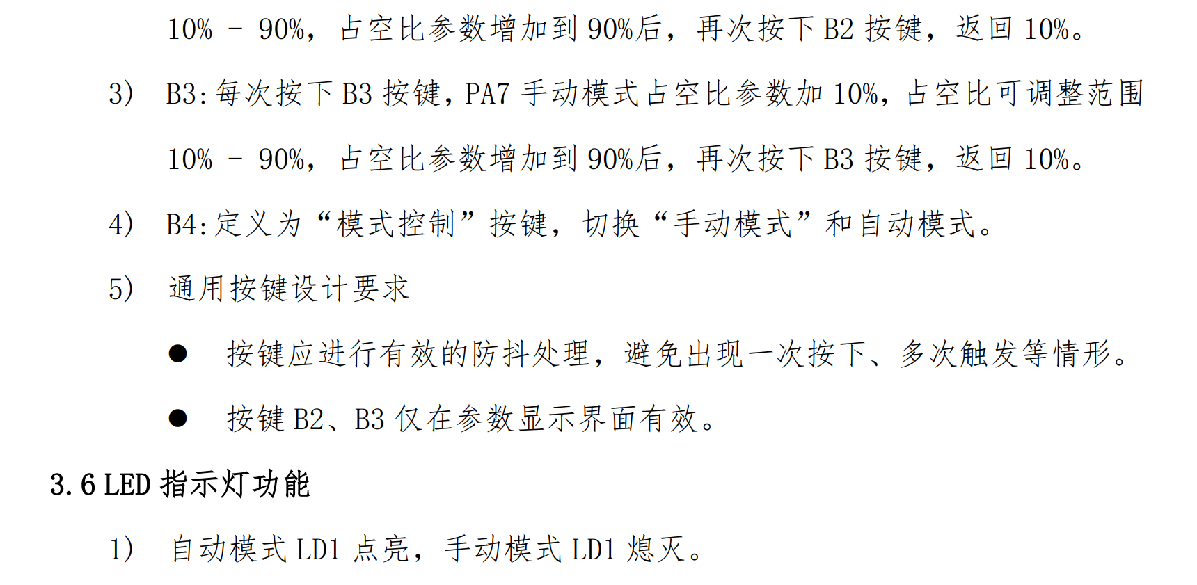
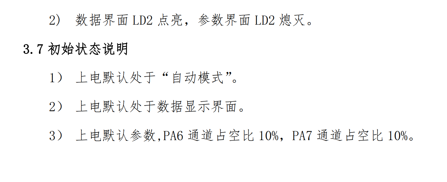
4, Summary
The difficulties of this test mainly include:
① Two different pwm duty cycles
- In order to output two pwm waves with different duty cycles, the output comparison mode can be adopted. The interrupt function will automatically reverse the level with opposite output polarity. We set the count value of comparison in the interrupt to achieve the waveform we need. This belongs to manual output of pwm wave.
- Implementation idea: this programming idea needs to have a sufficient understanding of the functions of CCR1, CCR2 and CNT registers. CCR registers will be continuously compared with the values in CNT registers. If they are equal, an interrupt will be generated. The polarity of the interrupt generated for the first time is configured at the time of initial configuration. At the beginning of the program, both CCR and CNT will be set to 0, and the interrupt will occur as soon as the timer interrupt is enabled, In the interrupt, judge which channel is interrupted, capture the value of the current CCR register pair, then use a flag bit to judge whether the current level is high or low, and then reset the current CCR value to meet our required frequency and duty cycle.
② The PWM duty cycle is constantly changing
- The duty cycle of pwm is the current voltage divided by 3.3.
- If the duty cycle is directly and continuously modified in the main cycle, pwm confusion will occur.
- Solution: in the tick timer interrupt service program, the pwm wave setting function is invoked and updated every 500ms.
③ There is no tool to measure pwm in hand
- Write channel 2 of timer 2 to capture pwm.
- As shown below: