
background
With the continuous improvement of science and technology and living standards, smart home products are constantly entering daily life. Smart home can make home appliances smarter and make life more comfortable. Smart home is also the product of the deepening development of the Internet. The Internet connects people. After further development, it forms the Internet of things, connecting people and things, things and things.
Considering that lamps and air conditioners are the most widely used household appliances, we can start with these two items to make a set of smart home system.
Project requirements
Design and make a set of smart home system, which can complete the control of lamps and air conditioning.
- Have the ability to control lamps and air conditioners on the central control panel
- Have the ability to control lamps and air conditioners in small programs
- Have the ability to control lamps by voice
Overall scheme
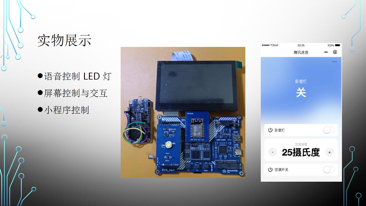
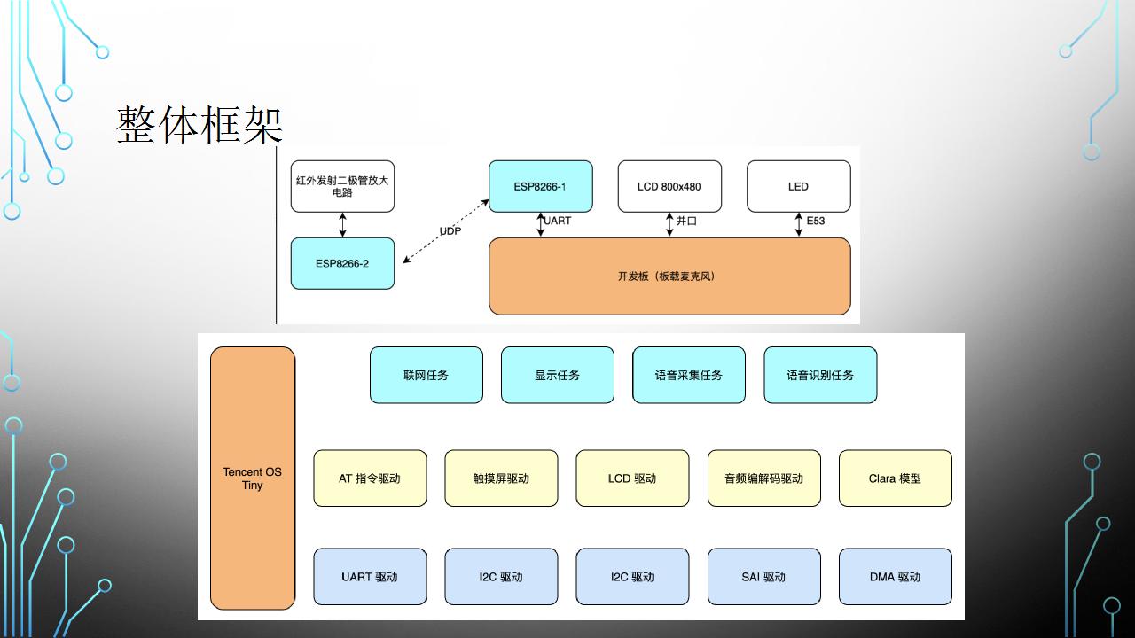
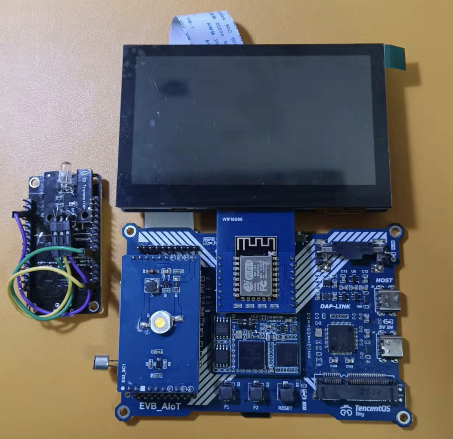
In terms of hardware, the RT1062 development board is used as the central control, an 800x480 screen is used to provide human-computer interaction, the LED lamp extension of E53 interface is used as a lamp, and the esp8266 module is used to provide networking capability for RT1062. In addition, esp8266 and infrared emission module are used as independent infrared remote controller. The overall hardware connection is shown in the figure below:

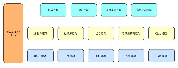
TencentOS Tiny is used in the software to provide the connection between task scheduling ability and mqtt, and Tencent cloud IoT development platform is used in the cloud to process data. The applet end is bound with Tencent serial applet to provide remote control capability.
The infrared remote control capability is provided by a separate esp8266 module. After receiving the UDP data packet in the LAN, the module parses it into the control instruction in json format, and then converts it into infrared coded data. Finally, the data is transmitted to the air conditioner through the infrared transmitting module.
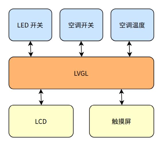
The overall software framework is shown in the figure below:
Scheme implementation details - driving part
Basic drive
Basic driver refers to the driver changed with the development board routine, which is not within the scope of this project, but it is more important.
The first is the transplantation of TencentOS Tiny. TencentOS Tiny's lightweight operating system for Internet of things devices can run on resource constrained MCU through cutting and configuration. The main steps of porting the real-time operating system are generating system beat, task switching and serial port output.
The second is to use external SDRAM. Because the project requires more external resources, the development board itself provides 16MB SDRAM, which can be used for display cache, etc. The driver of this part is written into the single chip microcomputer through the OCD module of RT1602. Without business code, it can ensure that the external SDRAM can be available after startup.
Then LCD driver. Using the enhanced LCD interface peripheral eLCDIF of RT1602 and the driver in the library function, combined with the available external SDRAM as the display memory, it is convenient to drive the 800x480 LCD of the development board.
Finally, voice driven. After the short-circuit problem of the development board mic is solved, the routine can be used to initialize the audio codec chip and complete the audio input and output.
GUI driver
The development board has its own LCD driver, but if you want to do human-computer interaction, you still need to transplant the corresponding GUI driver. This project uses lvgl as the GUI drawing layer, and this part of the code is obtained from the components of TencentOS Tiny.
Touch screen drive
An important part of human-computer interaction is to process input. The screen of the development board contains a touch screen, but it does not adapt to the touch screen driver.
The chip of the touch screen is GT911, which supports up to 5 touch points and is connected with the development board through I2C interface. In terms of software, consider using software to simulate I2C to quickly realize the drive.
First, transplant the driver of software I2C. Complete the control of GPIO according to the sequence diagram of I2C, and expose the following APIs:
      void    I2C_Send_Byte(uint8_t data);

      uint8_t I2C_Read_Byte(unsigned char ack);
The second is to transplant the driver of GT911. The screen has been written with configuration parameters at the factory, so there is no need to make complex configuration, and it can be used almost after power on.
After the initialization of the touch screen is completed, a pulse will be output through the INT pin whenever a touch event occurs. After capturing the falling edge of this pulse, the development board enters the interrupt program and sets the touch flag bit. If the application program wants to judge the touch event, first judge the flag bit. If it is set, first reset it, then read the register of the touch screen, and finally get the touch position.
The interrupt processing code is as follows:
 void GPIO5_Combined_0_15_IRQHandler(void) {
        GPIO_PortClearInterruptFlags(DEV_INT_GPIO, 1U << DEV_INT_PIN);
        Dev_Now.Touch = 1;
        SDK_ISR_EXIT_BARRIER;
      }
The code for reading keys is as follows:
void GT911_get_xy(int16_t* x, int16_t* y) {
        uint8_t buf[41];
        uint8_t Clearbuf = 0;
        uint8_t i;


        if (Dev_Now.Touch == 0) {
          *x = 0;
          *y = 0;
          return;
        }

        Dev_Now.Touch = 0;
        // See how many points there are
        GT911_RD_Reg(GT911_READ_XY_REG, buf, 1);
        Dev_Now.TouchpointFlag = buf[0];
        Dev_Now.TouchCount = buf[0] & 0x0f;
        if (Dev_Now.TouchCount > 5 || Dev_Now.TouchCount  == 0) {
          GT911_WR_Reg(GT911_READ_XY_REG, (uint8_t *) & Clearbuf, 1);
          tos_sleep_ms(10);
          return;
        }

        // Read only the first register here
        GT911_WR_Reg(GT911_READ_XY_REG, (uint8_t *)&Clearbuf, 1);
        tos_sleep_ms(10);

        GT911_RD_Reg(GT911_READ_XY_REG + 1, &buf[1], Dev_Now.TouchCount * 8);
        GT911_WR_Reg(GT911_READ_XY_REG, (uint8_t *) & Clearbuf, 1);
        tos_sleep_ms(10);

        Dev_Now.Touchkeytrackid[0] = buf[1];
        *x = ((uint16_t)buf[3] << 8) + buf[2];
        *y = ((uint16_t)buf[5] << 8) + buf[4];

        // Set to 0 after processing
        // If it is set to 0 at the beginning, the interrupt will occur at any time and will be set to 1 again
        Dev_Now.Touch = 0;

      }
LVGL transplantation
The transplantation of Lvgl includes several parts: the transplantation of output devices and the transplantation of input devices. The output device here is lcd screen, and the input device is touch screen. The output device adopts the scheme of double buffer, and the buffer size is the same as that of the screen, which can reduce the complexity of driver transplantation. The input device contains initialization and read coordinates.
Will LV_ port_ indev_ template. Copy C to lv_port_indev.c. Touchpad and_ Init initializes the touch screen:
static void touchpad_init(void)
{
    GT911_Init();
}
Then on touchpad_read out the corresponding coordinates in read
static bool touchpad_read(lv_indev_drv_t * indev_drv, lv_indev_data_t * data)
      {
          static lv_coord_t last_x = 0;
          static lv_coord_t last_y = 0;

          /*Save the pressed coordinates and the state*/
          if(touchpad_is_pressed()) {
              touchpad_get_xy(&last_x, &last_y);
              data->state = LV_INDEV_STATE_PR;
          } else {
              data->state = LV_INDEV_STATE_REL;
          }

          /*Set the last pressed coordinates*/
          data->point.x = last_x;
          data->point.y = last_y;

          /*Return `false` because we are not buffering and no more data to read*/
          return false;
      }

      /*Return true is the touchpad is pressed*/
      static bool touchpad_is_pressed(void) {
          /*Your code comes here*/
          return GT911_is_pressed();
      }

      /*Get the x and y coordinates if the touchpad is pressed*/
      static void touchpad_get_xy(lv_coord_t * x, lv_coord_t * y) {
        /*Your code comes here*/
        GT911_get_xy(x, y);
      }
Will LV_ port_ disp_ template. Copy C to lv_port_disp.c. And call the lcd driver. The code is as follows:
  static void disp_init(void)
      {
          /*You code here*/
          lcd_init();
      }

static void disp_flush(lv_disp_drv_t * disp_drv, const lv_area_t * area, lv_color_t * color_p)
 {
         /*The most simple case (but also the slowest) to put all pixels to the screen one-by-one*/
          // Here you can directly set the lcd to render the next frame
          lcd_flush(color_p);

          /* IMPORTANT!!!
           * Inform the graphics library that you are ready with the flushing*/

          lv_disp_flush_ready(disp_drv);
}
Infrared drive
The air conditioner used for the test is a Midea brand, and its control mode is somewhat special. First look at the infrared data coding.
The basic coding format is: L,A,A ', B,B', C,C ', S, L,A,A', B,B ', C,C'.
L is the pilot code; S is the separation code; A is the identification code (A=10110010=0xB2, in case of reservation scheme, A=10110111=0xB7), and a 'is the inverse code of a; B 'is the inverse code of B; C 'is the inverse of C.
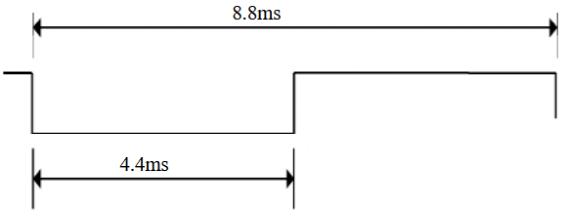
Boot code L:
Split Code:

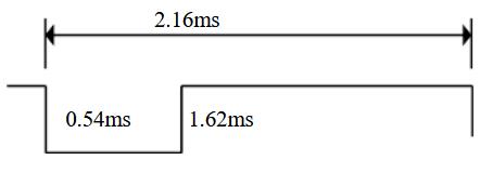
Data 1:
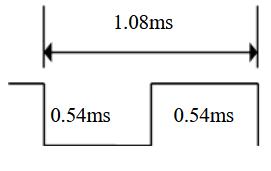
Data 0:
Terminator:

During normal wind speed, temperature and mode control, the values of B and C are set according to the following figure:
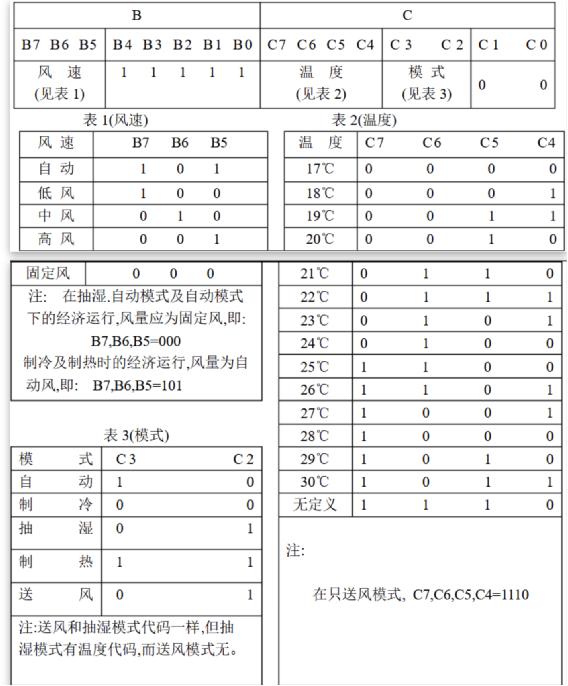
When shutdown, B is fixed as 0111 1011 (0x7b) and C is fixed as 1110 0000 (0xe0)
The infrared data array here is an important concept, which records the data composition of an infrared data frame. Every two elements of the array form a group, indicating the duration of low level and high level. The time unit is microseconds. An example is as follows:
C unsigned short int ir_data = [4400, 4400, 540, 1620, 540, 540, ..., 540]; |
|---|
The first two data indicate that the low level lasts for 4.4ms and then changes to the high level of 4.4ms. Compared with the physical layer protocol, this is a start bit; Then, the low level of 0.54ms and the high level of 1.62ms are continued, which is a data bit 1; Followed by a data bit 0; The last 540 represents a terminator.
The infrared remote controller is implemented on another piece of esp8266. The implementation scheme adopts IRbaby firmware https://github.com/Caffreyfans/IRbaby . Because Midea air conditioner needs special infrared data, IRbaby is finally customized. After understanding the implementation, you can see in Src / irbabyir It is convenient to customize in CPP. Comment out ir_decode function, and then write generate_midea_ac function replaces its function to get the infrared data array.
Scheme implementation details - Application Part
In terms of application, it is divided into four tasks: networking task, display task, audio acquisition task and audio recognition task. The code is as follows:
int main(void) {
  // Hardware initialization
  BOARD_ConfigMPU();
  BOARD_InitPins();
  BOARD_BootClockRUN();
  BOARD_InitDebugConsole();
  AUDIO_Init();

  PRINTF("Welcome to TencentOS tiny\r\n");

  osKernelInitialize();

  // Initialization semaphore
  tos_sem_create(&mic_data_ready_sem, 0);

  // Speech recognition task
  tos_task_create(&task1, "audio loop back task", audio_loop_back_task, NULL, 4, task1_stk, TASK1_STK_SIZE, 0);
  tos_task_create(&task2, "clara detection task", clara_detection_task, NULL, 3, task2_stk, TASK2_STK_SIZE, 0);

  // Connect to Tencent cloud IoT platform
  tos_task_create(&mqtt_task_t, "mqtt task", mqtt_task, NULL, 2, mqtt_task_stk, MQTT_STK_SIZE, 0);

  // Display task
  tos_task_create(&display_task_t, "display task", display_task, NULL, 4, display_task_stk, DISPLAY_STK_SIZE, 0);


  // Clara engine initialization
  int ret = Clara_create(&clara_heap[0], MEM_POOL_SIZE, SAMPLES_PER_FRAME, DEFAULT_DURATION_IN_SEC_AFTER_WUW);
  PRINTF("\n%s init[%d]\n", Clara_get_version(), ret);

  PRINTF("\r\nClara wakeup example started!\r\n");
  PRINTF("\r\nSay wakeup words: 1)Xiaozhi xiaozhi kai deng; 2)Xiaozhi xiaozhi guan deng; 3)Xiaozhi xiaozhi bian yan se\r\n");
  PRINTF("Trial version for 50 times wakeup test\r\n");
  PRINTF("Shout out the wake-up words: 1) Xiaozhi, turn on the light, 2) Xiaozhi, turn off the light, 3) Xiaozhi, change the color\r\n");
  PRINTF("50 Wake up trial\r\n\r\n");

  osKernelStart();
}
After completing the initialization of the development board, create four tasks in turn and execute task scheduling. Pay attention to the priority of tasks here. The networking task of mqtt belongs to high priority and is set to 2; Both audio acquisition and interface refresh need to be performed periodically, and the priority is set to 4; If the audio buffer is full, priority should be given to audio recognition, so the priority of audio recognition task is set to 3
Networking tasks
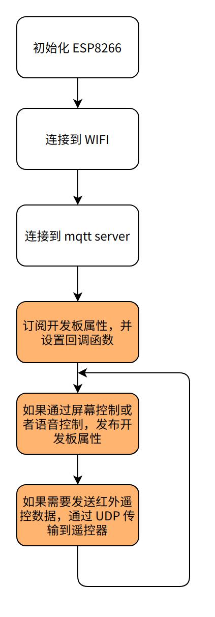
The purpose of the task is to access the mqtt server of Tencent cloud IoT development platform through WIFI, subscribe to the topic of the development board, and synchronize to the cloud in time when the properties of the development board change.
Access mqtt
The esp8266 at driver has been completed by TencentOS Tiny. We only need to access Tencent cloud IoT development platform step by step. The main workflow is as follows
Lamp control
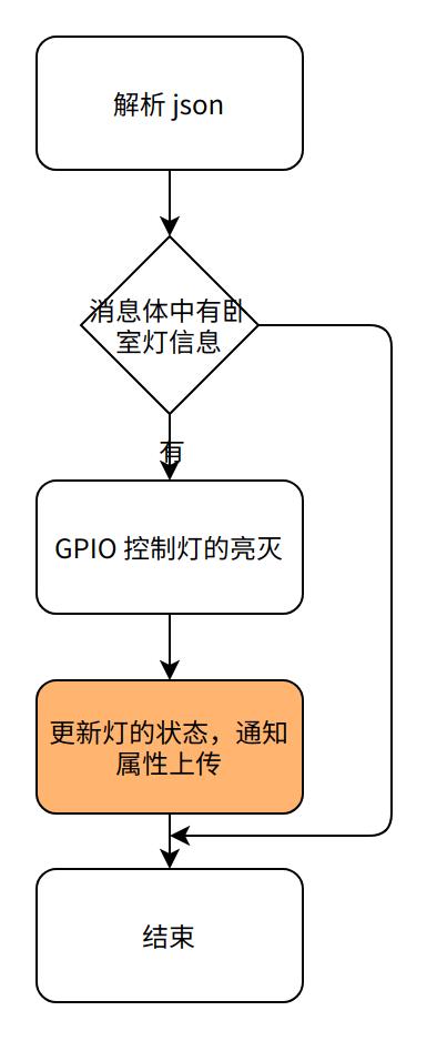
The development board comes with an E53 interface LED lamp, which can be used to simulate lamps. The control of lamps is a simple switching value. The data template of bedroom lamps is newly built on the IoT development platform, and the control components of lamps are newly built on the applet side, as shown in the figure below.


The main flow of callback function is as follows:
Air conditioning control
In the above, the underlying control logic of Midea air conditioner has been solved, and the application part mainly solves the communication between user interface and applet and intelligent central control.
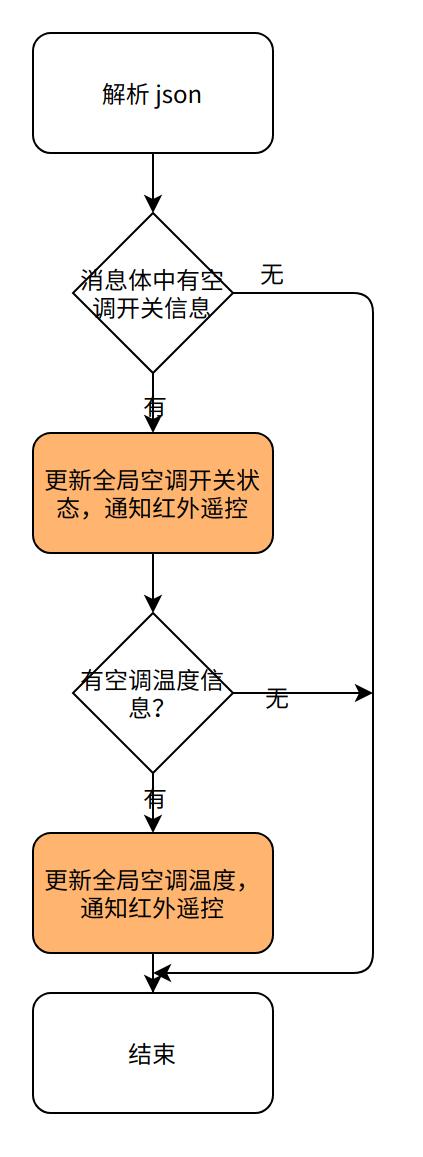
Considering that the basic function of air conditioner is switch + temperature control, a data template of development quantity and an integer data template are newly built, in which the air conditioner temperature should be set to 16 at the lowest and 28 at the highest.

The processing flow of the callback function is as follows:
Display task
This task is used to drive the normal display of lvgl and draw the switch control and spinner control at the same time.
Interface drawing
Using the control library of lvgl, three controls are designed and made: light switch, air conditioning switch and air conditioning temperature control.
The key codes are as follows:
// light
  lv_obj_t* light_text = lv_label_create(lv_scr_act(), NULL);
  lv_obj_align(light_text, NULL, LV_ALIGN_CENTER, -20, -20);
  lv_label_set_text(light_text, "light");
  light_sw = lv_sw_create(lv_scr_act(), NULL);
  lv_obj_align(light_sw, light_text, LV_ALIGN_OUT_RIGHT_MID, 10, 0);
  lv_obj_set_event_cb(light_sw, light_event_handler);

  // ac
  lv_obj_t* ac_text = lv_label_create(lv_scr_act(), NULL);
  lv_obj_align(ac_text, NULL, LV_ALIGN_CENTER, -20, 20);
  lv_label_set_text(ac_text, "ac_on");
  ac_sw = lv_sw_create(lv_scr_act(), NULL);
  lv_obj_align(ac_sw, ac_text, LV_ALIGN_OUT_RIGHT_MID, 8, 0);
  lv_obj_set_event_cb(ac_sw, ac_event_handler);

  // ac temp
  spinbox = lv_spinbox_create(lv_scr_act(), NULL);
  lv_spinbox_set_range(spinbox, 16, 28);
  lv_spinbox_set_digit_format(spinbox, 2, 0);
  lv_spinbox_step_prev(spinbox);
  lv_obj_set_width(spinbox, 100);
  lv_obj_align(spinbox, ac_text, LV_ALIGN_OUT_BOTTOM_MID, 20, 20);
  lv_spinbox_step_next(spinbox);
The actual display effect is shown in the figure below:
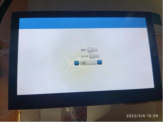
Cyclic Refresh
Lvgl needs to execute LV on a regular basis_ task_ Handler function and put it into the display task.
void display_task(void *arg) {
  PRINTF("begin init lcd...");
  lv_init();
  lv_port_disp_init();
  lv_port_indev_init();
  PRINTF("lcd init done.");

  PRINTF("begin init touch screen");
  GT911_Init();
  PRINTF("init touch screen done");
  demo_create();

  while (1) {
    lv_task_handler();
    tos_sleep_ms(200);
  }
}
At the same time, lvgl also requires the implementation of LV on a regular basis_ tick_ Inc function and put it into SysTick_Handler.
void SysTick_Handler(void)
{
  if (tos_knl_is_running())
  {
    tos_knl_irq_enter();
    tos_tick_handler();
    tos_knl_irq_leave();
  }
  // For lvgl's tick, pay attention to configuring systick to 1ms
  lv_tick_inc(1);
}
Audio acquisition and recognition task

The purpose of audio acquisition is to receive data frame by frame from the codec chip, and notify the recognition task for recognition after processing.
void audio_loop_back_task(void *arg)
{

  while (1) {
    // If the buffer is idle, start the dma transmission task
    if (emptyBlock > 0) {
      xfer.data     = Buffer + rx_index * BUFFER_SIZE;
      xfer.dataSize = BUFFER_SIZE;
      if (kStatus_Success == SAI_TransferReceiveEDMA(DEMO_SAI, &rxHandle, &xfer)) {
        mic_frame_preprocess((uint16_t *)(xfer.data), xfer.dataSize/2);
        tos_sem_post(&mic_data_ready_sem);
        rx_index++;
      }
      if (rx_index == BUFFER_NUMBER) {
        rx_index = 0U;
      }
    }
   }
}
The trained Clara speech recognition model is used for audio recognition. If the corresponding speech is matched, the keyword id will be given. According to the keyword id, you can control the light on and off.
void clara_detection_task(void *arg)
{
  extern uint16_t mic_16khz_buffer[];

  int frame_cnt = 0;
  int kw_total_num = 0;
  int light_duration = 0;
  int kw_detected = 0;

  while(1)
  {
    tos_sem_pend(&mic_data_ready_sem, -1); //pend forever until mic audio ready

    kw_detected = Clara_put_audio_two_phases(mic_16khz_buffer, SAMPLES_PER_FRAME, &clara_result);

    if (kw_detected > 0)
    {
      kw_total_num++;

      // check wakeup result
      PRINTF("\n[ClrDbg]  Vox-AI: Clara got %d:%s (utf8 %dB) duration %d ms, score %d, conf %d, total %d\n", \
                    clara_result.kws_id, clara_result.kws, clara_result.kws_len,clara_result.duration,
             clara_result.score, clara_result.confidence, kw_total_num);
      if (clara_result.kws_id == 17) {
        ctrl_light(1);
      } else if (clara_result.kws_id == 18) {
        ctrl_light(0);
      }

    }

  }
}