Leading knowledge
GPIO principle
STM32 model description
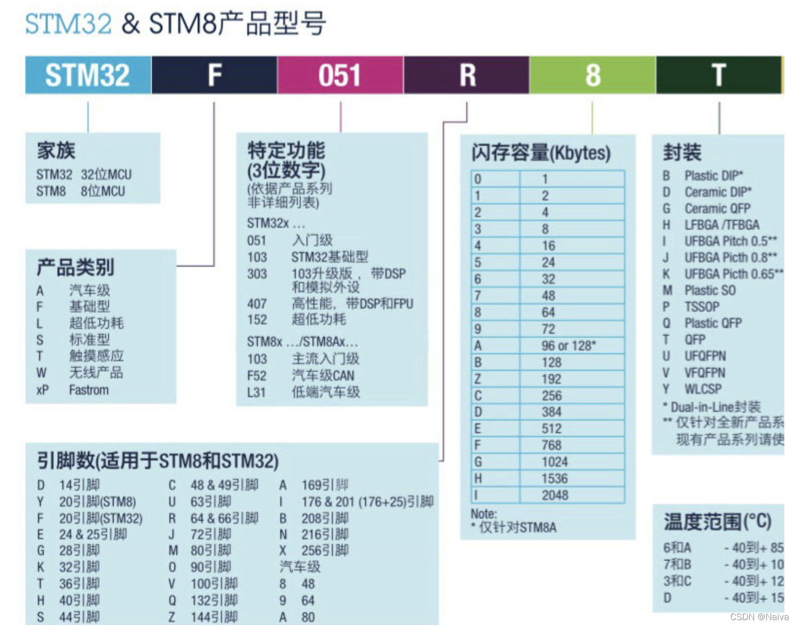
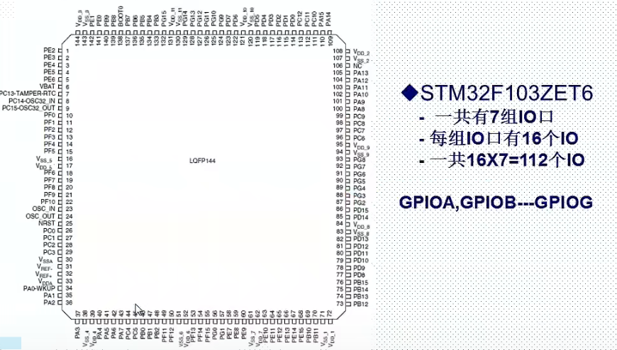
Stm32f103zet6: 144 pin, 512K flash memory
- 7 sets of IO ports (GPIOA... GPIOG)
- 16 IO ports per group
- Total: 112 IO ports
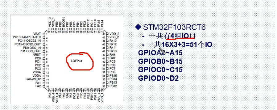
STM32F103RCT6: 64 pin, 256K flash memory
- 4 sets of IO ports (GPIOA... GPIOG)
- There are 16 IO ports in each group from gpioa to gpioc; GPIOD13 IO ports
- Total: 51 IO ports
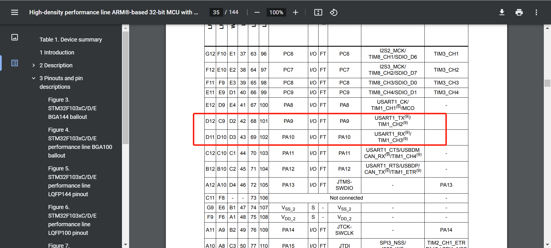
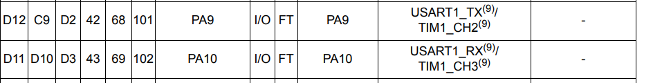
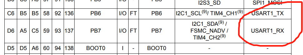
The following can be seen in the chip data book - STM32F103VET6:
PA9 and PA10 can be used not only as general IO ports, but also as URAT and timer.
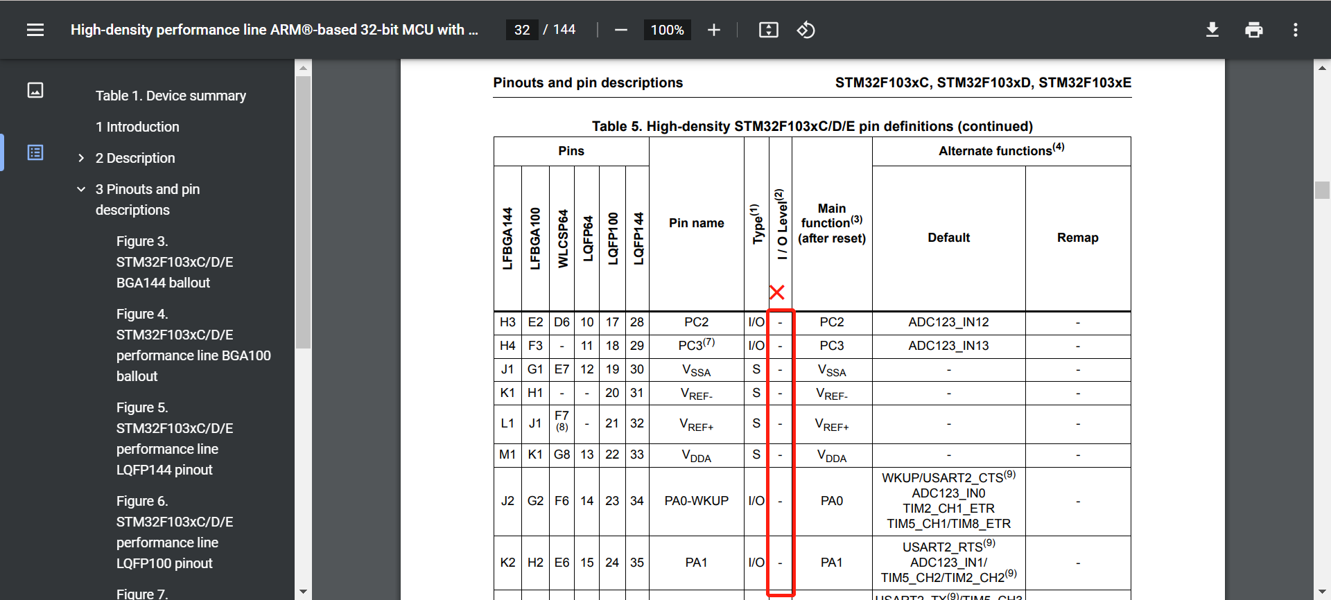
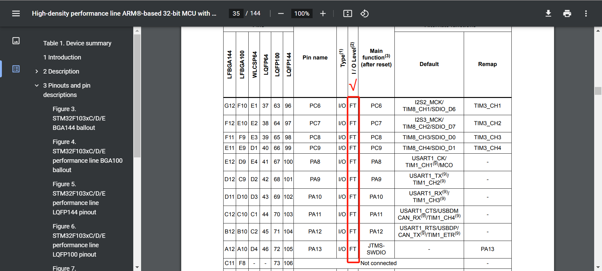
STM32 Chinese reference manual _V10 - 8 General and multiplex function I/O(GPIO and AFIO) can see:
The IO port of STM32 with FT identification can tolerate 5V.
Small capacity products refer to STM32F101xx, STM32F102xx and STM32F103xx microcontrollers with flash memory capacity between 16K and 32K bytes.
Medium capacity products refer to STM32F101xx, STM32F102xx and STM32F103xx microcontrollers with flash memory capacity between 64K and 128K bytes.
High capacity products refer to STM32F101xx and STM32F103xx microcontrollers with flash memory capacity between 256K and 512K bytes.
Interconnected products refer to STM32F105xx and STM32F107xx micro control.
Unless otherwise specified, the modules described in this chapter are applicable to the whole STM32F10xxx microcontroller series.
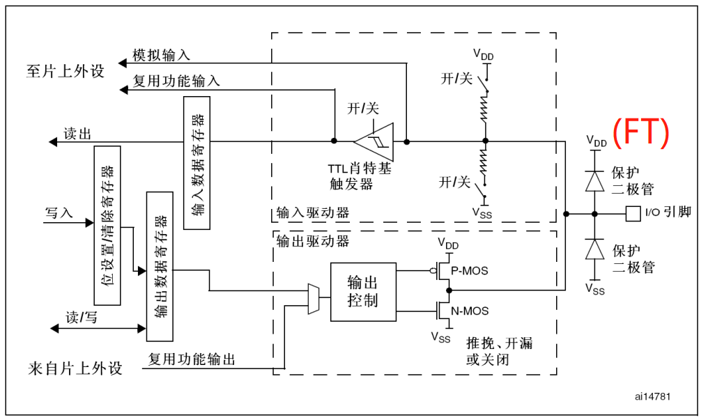
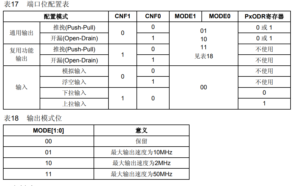
GPIO port 8 I / O modes
You can use stm32f10x again_ gpio. H view working mode in header file
typedef enum
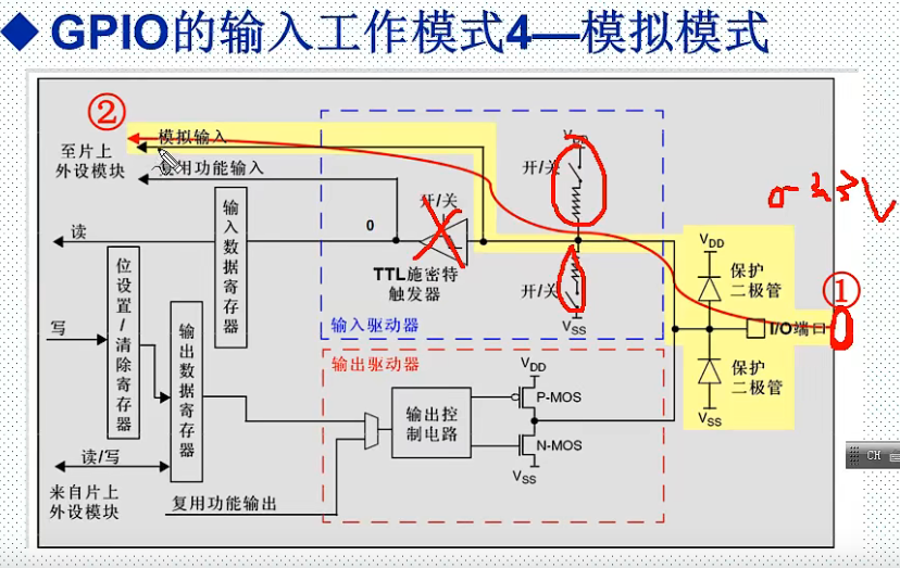
{ GPIO_Mode_AIN = 0x0,//Analog input
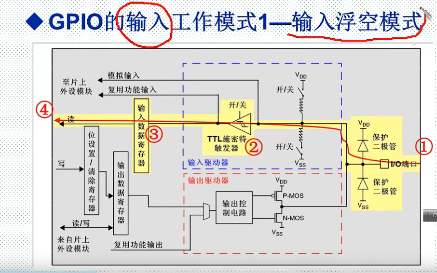
GPIO_Mode_IN_FLOATING = 0x04,//Floating input
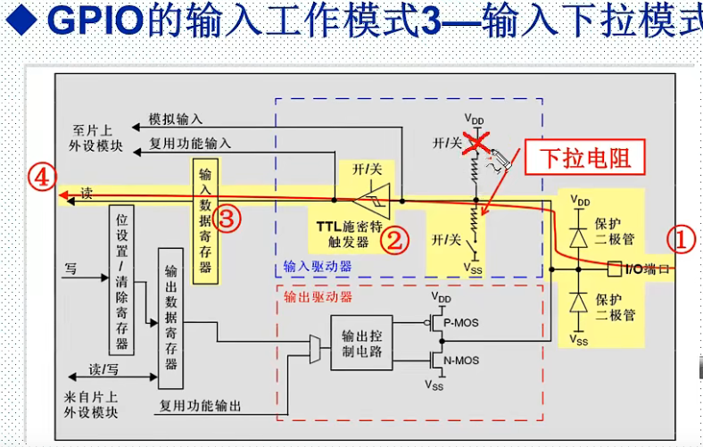
GPIO_Mode_IPD = 0x28,//Drop down input
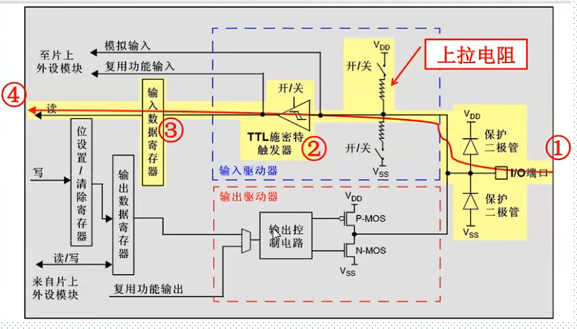
GPIO_Mode_IPU = 0x48,//Pull up input
GPIO_Mode_Out_OD = 0x14,//Open drain output
GPIO_Mode_Out_PP = 0x10, //push-pull outputs
GPIO_Mode_AF_OD = 0x1C,//Open drain multiplex output
GPIO_Mode_AF_PP = 0x18//Push pull multiplex output
}GPIOMode_TypeDef;
4 input modes:
- Input float
- Input pull-up
- Input drop-down
- Analog input
4 output modes:
- Open drain output
- push-pull outputs
- Push pull multiplexing function
- Open drain multiplexing function
3 maximum turning speeds:
- 2 MHz
- 10 MHz
- 50 MHz
The flip speed is used to configure registers in the program.
The external input level can be read in floating input mode.
30K~50K pull-up resistance
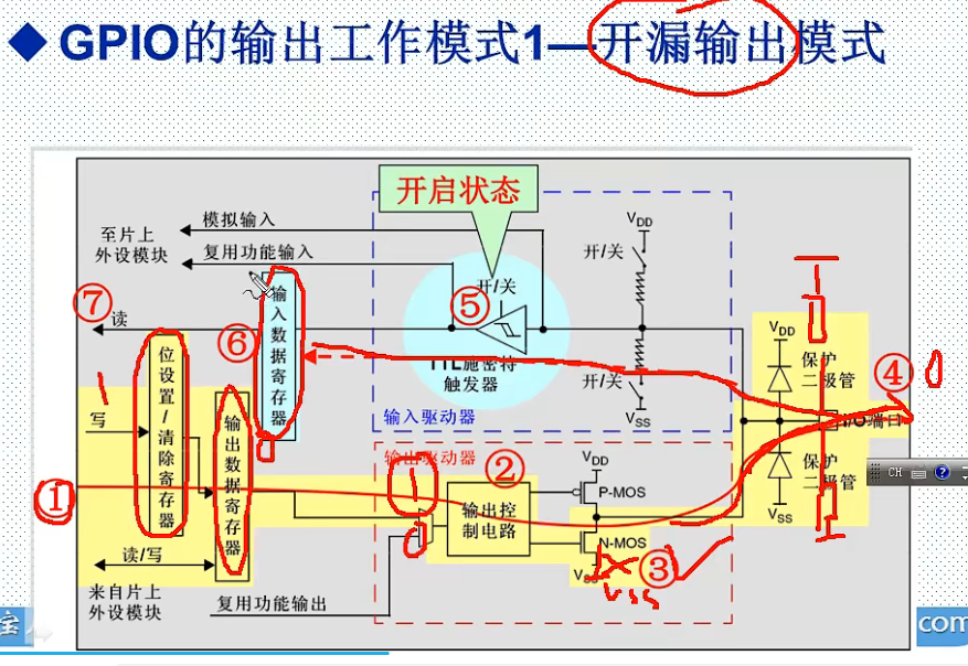
Open drain output mode
Write bit set / clear register output data register output driver
Output 1: the N-MOS tube is disconnected, and the chip CPU reads the external Vdd/Vss level
Output 0: the N-MOS tube is turned on, and the chip CPU reads "0"
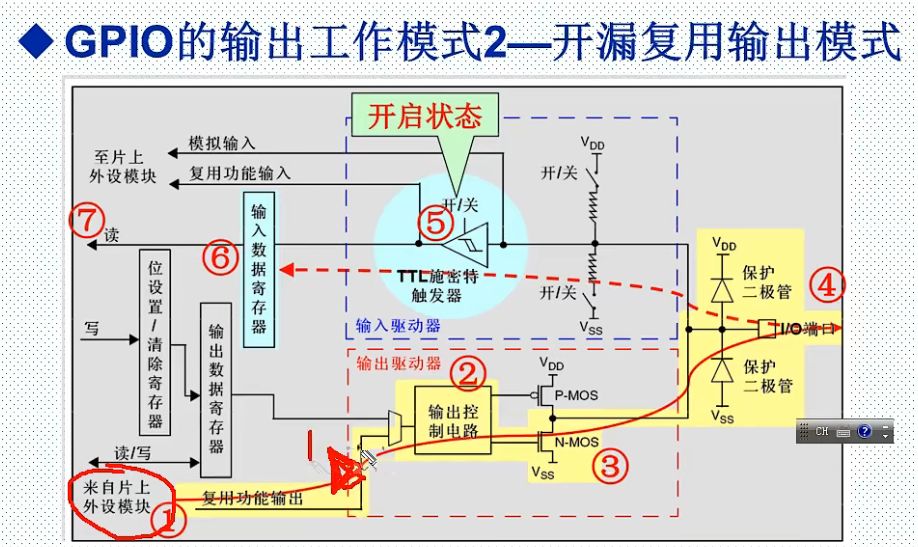
The open drain multiplex output is similar to the open drain output. The difference between the two is that the open drain output mode is the internal CPU write register output, while the open drain multiplex output is through peripherals.
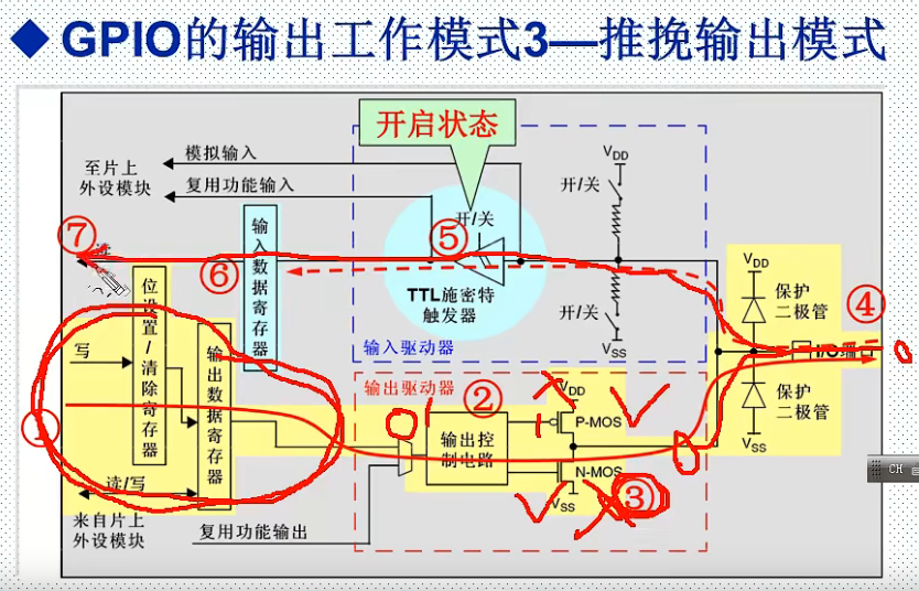
Push pull output mode
Output 1: P-MOS tube is on, N-MOS tube is off, and the output is 1
Output 0: P-MOS tube is off, N-MOS tube is on, output 0
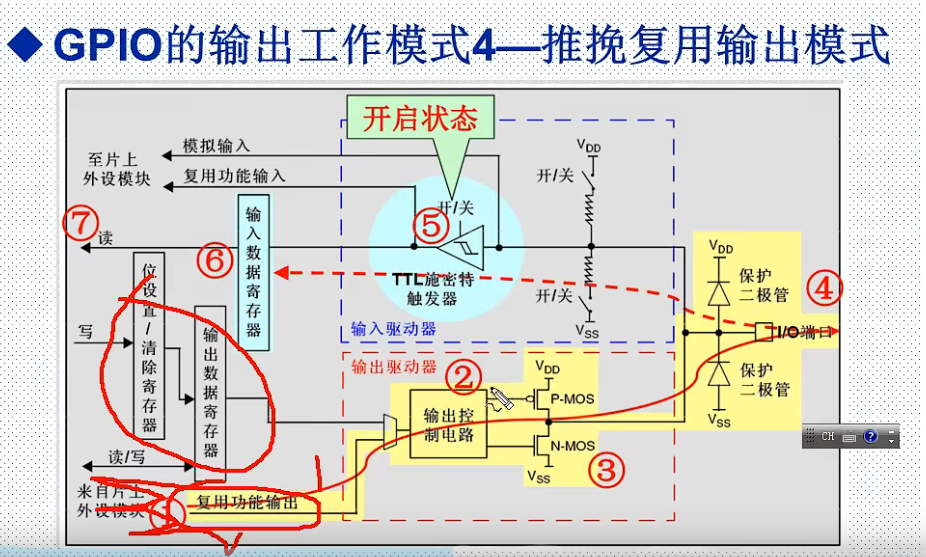
The difference between push-pull multiplex output mode and push-pull output mode is that the input of multiplexing function is not the CPU control register.
GPIO port 7 registers
- 2 32-bit configuration registers (GPIOx_CRL, GPIOx_CRH)
- 2 32-bit data registers (GPIOx_IDR and GPIOx_ODR)
- 1 32-bit / reset register (GPIOx_BSRR)
- 1 16 bit reset register (GPIOx_BRR)
- 1 32-bit lock register (GPIOx_LCKR)
According to the specific hardware characteristics of each I/O port listed in the data manual, each bit of GPIO port can be configured into multiple modes by software.
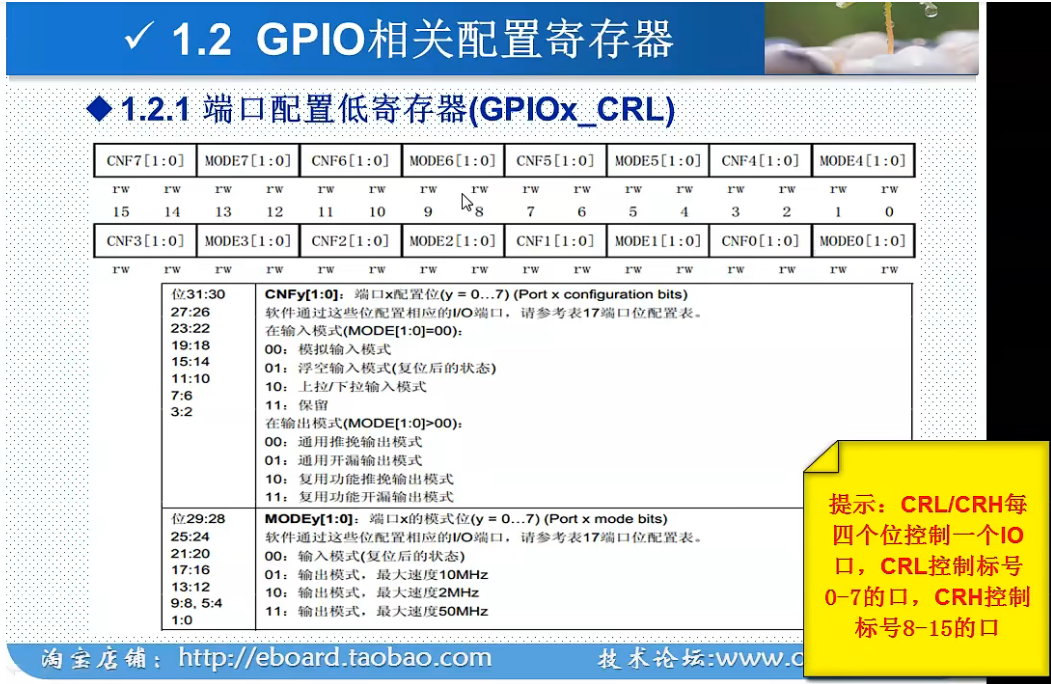
2 32-bit configuration registers (GPIOx_CRL, GPIOx_CRH)
Why are 32-bit registers configured as 2?
CRL/CRH is configured with one IO port every 4 bits, and each group has 16 IO ports, so two 32-bit registers are required, a total of 64 bits.
- CRL control label is IO port 0 ~ 7
- CRH control label is IO port 8 ~ 15
Port configuration low register GPIOx_CRL
GPIOA0 : CNF0[1:0] MODE0[1:0]
Gpioa1: CNF1 [0:0] mode1 [0:0] (00 indicates: in analog input mode; input mode)
GPIOA2
GPIOA3
GPIOA4
GPIOA5
GPIOA6
GPIOA7: CNF7[1:0] MODE7[1:0] (10 indicates: under the push-pull output mode of multiplexing function; the maximum turnover speed of output mode is 2MHz)
Port configuration high register GPIOx_CRH
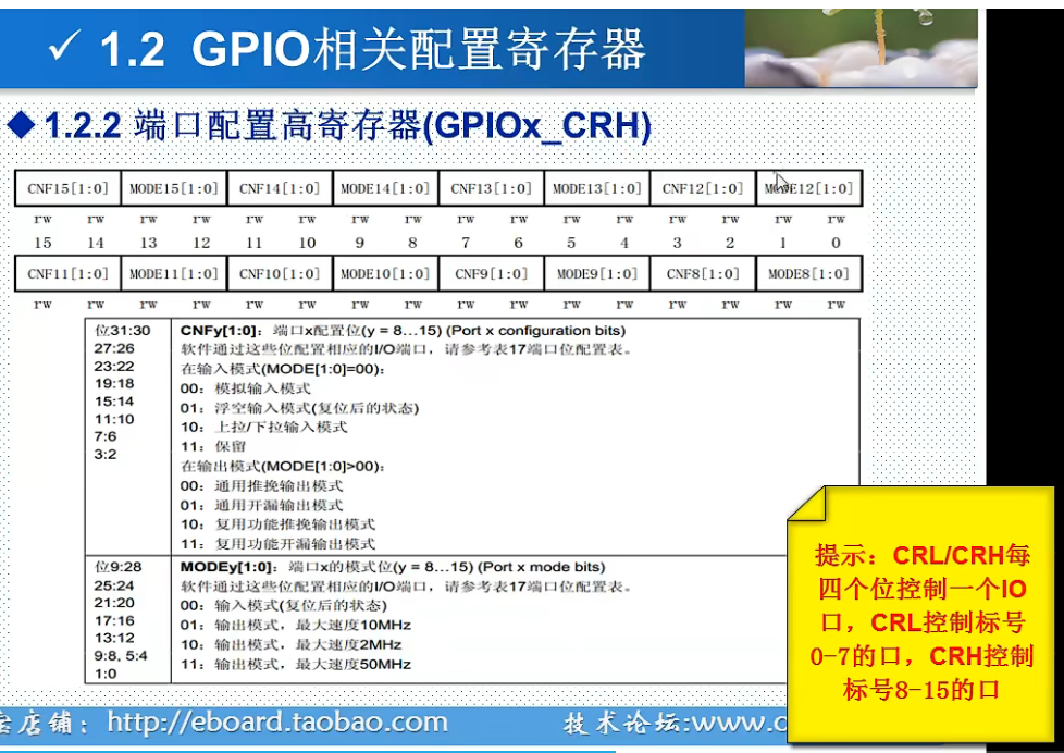
GPIOA8 :CNF0[1:0] MODE0[1:0]
GPIOA9
GPIOA10
GPIOA11
GPIOA12
GPIOA13
GPIOA14
GPIOA15 :CNF7[1:0] MODE7[1:0]
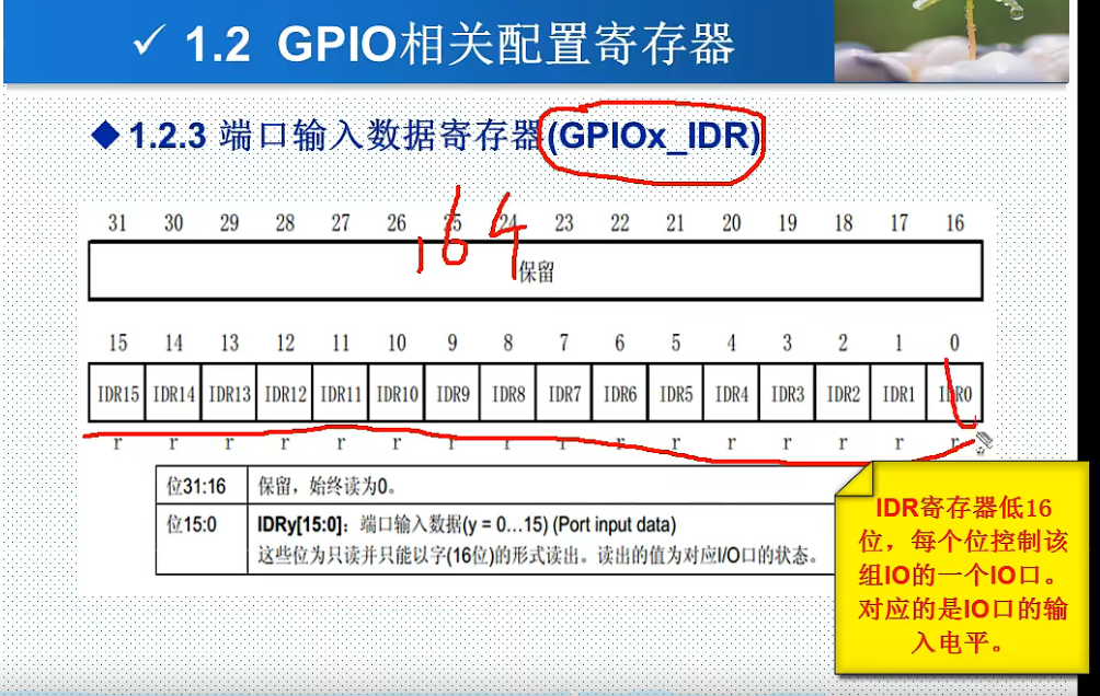
2 32-bit data registers (GPIOx_IDR and GPIOx_ODR)
Port input data register GPIOx_IDR
- The lower 16 bits of IDR register control one IO port of this group of Io. Corresponding to the input level of IO port.
Only 0 ~ 15 bits are used and 16 ~ 31 bits are reserved.
Port output data register GPIOx_ODR
- The lower 16 bits of ODR register control one IO port of this group of Io. Corresponding to the input level of IO port. Only 0 ~ 15 bits are used and 16 ~ 31 bits are reserved.
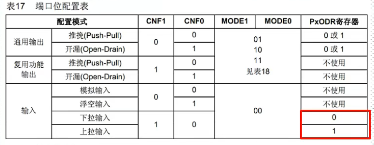
The ODR register can also set the pull-up / pull-down mode, for example:
GPIOA0 : CNF0[1:0] MODE0[1:0] P0ODR0[0:0]
Indicates: pull-up / pull-down input mode; Input mode; drop-down
1 32-bit / reset register (GPIOx_BSRR)
If the lower 16 bits of BSRR register and the corresponding bit is set to 1, then the IO buckle output is high level and the corresponding bit is set to 0, the corresponding IO port will not be affected. High 16 bits have the opposite effect.
For example:
GPIOA0_BSRR (PA0 port): 0000 0001
GPIOA9_BSRR (PA9 port), GPIOA0_BSRR (PA0 port): 0000 0010 0000 0001
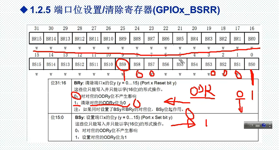
Note: usually only gpiox is used_ Lower 16 bits of bsrr register, gpiox_ The upper 16 bits of the BRR register.
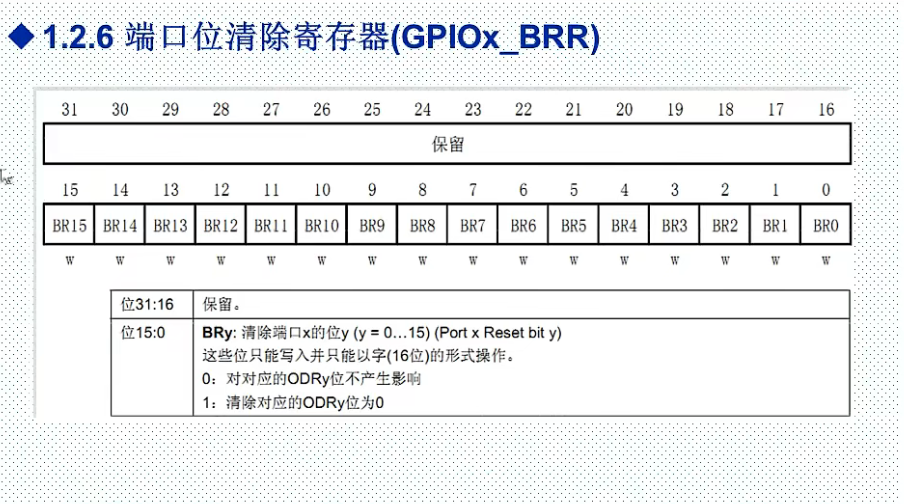
1 16 bit reset register (GPIOx_BRR)
1 32-bit lock register (GPIOx_LCKR)
slightly
STM32 pin description
Port multiplexing function
Most ports of STM32 have multiplexing function.
The so-called multiplexing means that some ports can not only be used as a general IO port, but also be reused as some peripheral pins. For example, PA9 and PA10 can be reused as the serial port 1 pin of STM32.
Function: make maximum use of port resources.
Port remapping function
Some functional pins can be mapped to other pins.
For example, the default pin of serial port 1 is PA9, and PA10 can remap large pb6 and pb7 through configuration
Function: convenient wiring.
All IO ports can be used as interrupt inputs
slightly
Introduction to GPIO library functions
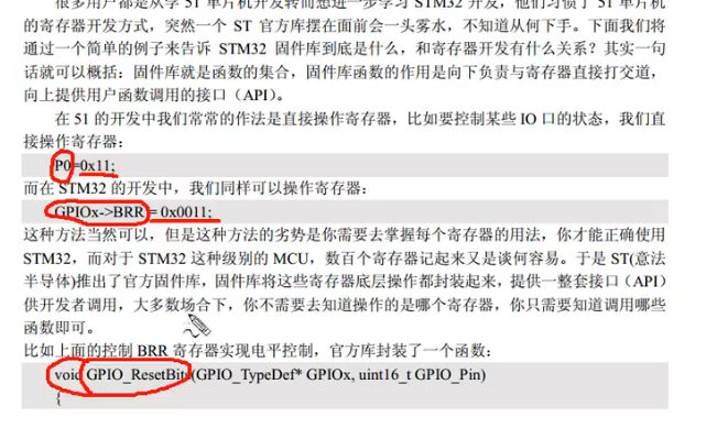
What is the difference between library functions and registers?
It's essentially the same. We can directly operate registers in the library function template, because the official library related header file has register definitions. However, the library function cannot be called in the register template because there is no definition related to the import / export function.
The purpose of understanding the basic principle of register is to let us have a more in-depth understanding of STM32, so that the Chinese side can be handy and comfortable in the development process. If the underlying code configuration is a problem and needs debugging, you must have a certain understanding of the register to find the problem, because when debugging the code, the underlying can only view the relevant configuration of the register.
Important functions:
1 initialization function
- void GPIO_Init(GPIO_TypeDef* GPIOx, GPIO_InitTypeDef* GPIO_InitStruct);

Parameters in function:
- GPIO_TypeDef* GPIOx: determine which group of IO ports need to be set and the number of groups, for example: GPIOB
- GPIO_InitTypeDef* GPIO_InitStruct
Function: initialize the working mode and speed of one or more IO ports (the same group).
Note: this function mainly operates GPIO_ For CRL (CRH) register, BSRR or BRR register is set during pull-up or pull-down.
Note: almost all peripherals (including GPIO) must enable the corresponding clock before use.
Parameter 1 structure type: GPIO_TypeDef
typedef struct
{
  __IO uint32_t CRL;
  __IO uint32_t CRH;
  __IO uint32_t IDR;
  __IO uint32_t ODR;
  __IO uint32_t BSRR;
  __IO uint32_t BRR;
  __IO uint32_t LCKR;
} GPIO_TypeDef;
Validity of parameter 1: GPIOA ~ GPIOG
#define IS_GPIO_ALL_PERIPH(PERIPH) (((PERIPH) == GPIOA) || \
                                    ((PERIPH) == GPIOB) || \
                                    ((PERIPH) == GPIOC) || \
                                    ((PERIPH) == GPIOD) || \
                                    ((PERIPH) == GPIOE) || \
                                    ((PERIPH) == GPIOF) || \
                                    ((PERIPH) == GPIOG))
Parameter 2: GPIO_InitTypeDef
typedef struct
{
  uint16_t GPIO_Pin;             // Specify the IO port to initialize
  GPIOSpeed_TypeDef GPIO_Speed; // Set the output speed of IO port
  GPIOMode_TypeDef GPIO_Mode;    //Set working mode: one of 8 working modes
}GPIO_InitTypeDef;

/*
typedef enum
{ GPIO_Mode_AIN = 0x0,//Analog input
  GPIO_Mode_IN_FLOATING = 0x04,//Floating input
  GPIO_Mode_IPD = 0x28,//Drop down input
  GPIO_Mode_IPU = 0x48,//Pull up input

  GPIO_Mode_Out_OD = 0x14,//Open drain output
  GPIO_Mode_Out_PP = 0x10, //push-pull outputs
  GPIO_Mode_AF_OD = 0x1C,//Open drain multiplex output
  GPIO_Mode_AF_PP = 0x18//Push pull multiplex output
}GPIOMode_TypeDef;

*/
GPIO_Init initialization function example:
	GPIO_InitTypeDef GPIO_InitStructure;  // Declare GPIO_InitTypeDef struct type

	GPIO_InitStructure.GPIO_Pin = GPIO_Pin_10;        // BEEP->PB. 10 port configuration validity is GPIO_ALL
    GPIO_InitStructure.GPIO_Speed = GPIO_Speed_50MHz; //Speed set to 50MHz validity: GPIO_Speed_10MHz = 1,GPIO_Speed_2MHz, GPIO_Speed_50MHz
	GPIO_InitStructure.GPIO_Mode = GPIO_Mode_Out_PP; //Push pull output

	GPIO_Init(GPIOB, &GPIO_InitStructure);            //Initialize the GPIOB of the GPIOB group according to the above member parameters 10 ports
2 read input level functions
- uint8_t GPIO_ReadInputDataBit(GPIO_TypeDef* GPIOx, uint16_t GPIO_Pin);
Function: read the input level of a GPIO. The actual operation is GPIOx_IDR register
GPIO_ReadInputDataBit initialization function example:
GPIO_ReadInputDataBit(GPIOA, GPIO_Pin5);//Read gpioa 5 input level
- uint16_t GPIO_ReadInputData(GPIO_TypeDef* GPIOx);
Function: read the input level of a group of GPIO. The actual operation is GPIOx_IDR register
GPIO_ReadInputData initialization function example:
GPIO_ReadInputData(GPIOA); read GPIOA All in group IO Input level of port
2 read output level functions
- uint8_t GPIO_ReadOutputDataBit(GPIO_TypeDef* GPIOx, uint16_t GPIO_Pin);
Function: read the output level of a GPIO. The actual operation is GPIOx_IDR register
GPIO_ReadOutputDataBit initialization function example:
GPIO_ReadOutputDataBit(GPIOA, GPIO_Pin5);//Read gpioa Output level of 5
- uint16_t GPIO_ReadOutputData(GPIO_TypeDef* GPIOx);
Function: read the output level of a group of GPIO. The actual operation is GPIOx_IDR register
GPIO_ReadOutputData initialization function example:
GPIO_ReadOutputData(GPIOA); read GPIOA All in group IO Output level of port
4 set output level functions
- void GPIO_SetBits(GPIO_TypeDef* GPIOx, uint16_t GPIO_Pin);
Function: set the output of an IO port to high level (1). The actual operation is the BSRR register.
Enter #include "stm32f10x_gpio.h" to view GPIO_SetBits function.
void GPIO_SetBits(GPIO_TypeDef* GPIOx, uint16_t GPIO_Pin)
{
  /* Check the parameters */
  assert_param(IS_GPIO_ALL_PERIPH(GPIOx));
  assert_param(IS_GPIO_PIN(GPIO_Pin));

  GPIOx->BSRR = GPIO_Pin;
}
- void GPIO_ResetBits(GPIO_TypeDef* GPIOx, uint16_t GPIO_Pin);
Function: set the output of an IO port to low level (0). The actual operation is BRR register.
void GPIO_ResetBits(GPIO_TypeDef* GPIOx, uint16_t GPIO_Pin)
{
  /* Check the parameters */
  assert_param(IS_GPIO_ALL_PERIPH(GPIOx));
  assert_param(IS_GPIO_PIN(GPIO_Pin));

  GPIOx->BRR = GPIO_Pin;
}
- void GPIO_WriteBit(GPIO_TypeDef* GPIOx, uint16_t GPIO_Pin, BitAction BitVal);
slightly
- void GPIO_Write(GPIO_TypeDef* GPIOx, uint16_t PortVal);
slightly
Experiment: LED water lamp
Running lamp experiment steps
- Enable IO port clock. Call RCC_APB2PeriphColckCmd(); Function.
Note: the clock bit of the corresponding IO port must be enabled before operating the IO port; Different IO groups call different clock enabling functions.
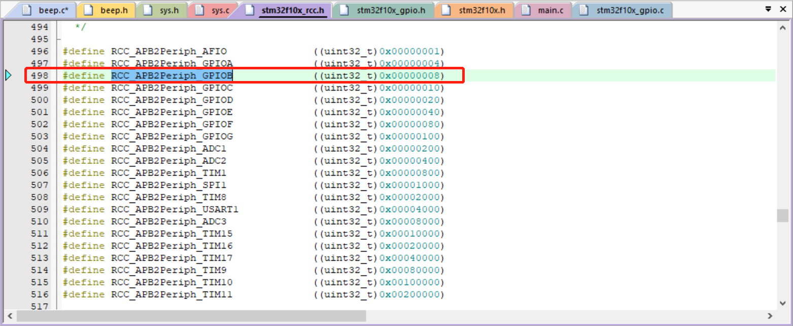
Parameter 1: as shown in the figure above
Parameter 2: ENABLE or DISABLE
	RCC_APB2PeriphClockCmd(RCC_APB2Periph_GPIOB, ENABLE);   // GPIOB clock enable port
	//RCC_APB2PeriphClockCmd(RCC_APB2Periph_GPIOA, DISABLE); //  Gpioa port clock is not enabled
- Initialize IO port mode. Call function GPIO_Init();
- Operate the IO port to output high and low levels. Call GPIO_SetBits(); And GPIO_ResetBits(); Function.
New file and code
Create a new [HARDWARE] folder in the project, and then create a new LED in the folder C and led H two documents and follow Operation mode of previously created project template Add Files and specify the header file path.
Learn more:
Use #ifndef #define #endif file to compile in header file to avoid repeated definition of header file content.
led.h
#ifndef __LED_H
#define __LED_H

void LED_Init(void);
#endif
led.c
#include "led.h"
#include "stm32f10x.h"

void LED_Init(void)
{
	GPIO_InitTypeDef GPIO_InitStructure;

	RCC_APB2PeriphClockCmd(RCC_APB2Periph_GPIOB, ENABLE);// Enable the GPIOB port clock. Note: you need to reference stm32xxx H header file
	RCC_APB2PeriphClockCmd(RCC_APB2Periph_GPIOD, ENABLE);// Enable GPIOE port clock
	//RCC_APB2PeriphClockCmd(RCC_APB2Periph_GPIOA, ENABLE);//  Enable GPIOB port clock

	GPIO_InitStructure.GPIO_Pin = GPIO_Pin_10;        // LED->PB. 10 port configuration
	GPIO_InitStructure.GPIO_Mode = GPIO_Mode_Out_PP; //Push pull output
	GPIO_InitStructure.GPIO_Speed = GPIO_Speed_50MHz; //The speed is set to 50MHz
	GPIO_Init(GPIOB, &GPIO_InitStructure);            //Initialize gpiob according to parameters ten
    GPIO_ResetBits(GPIOB,GPIO_Pin_10); // Set GPIOB for GPIOB group 10 output 0, turn off IO output


	GPIO_InitStructure.GPIO_Pin = GPIO_Pin_10;        // LED->PD. 10 port configuration
	GPIO_InitStructure.GPIO_Mode = GPIO_Mode_Out_PP; //Push pull output
	GPIO_InitStructure.GPIO_Speed = GPIO_Speed_50MHz; //The speed is set to 50MHz
	GPIO_Init(GPIOD, &GPIO_InitStructure);            //Initialize gpiod according to parameters ten
    GPIO_ResetBits(GPIOD,GPIO_Pin_10); // Set GPIOD for GPIOD group 10 output 0, turn off IO output

}
main.c
#include "stm32f10x.h"
#include "led.h"

int main(void){

while(1)
{
GPIO_SetBits(GPIOB,GPIO_Pin_10); // GPIO_SetBits sets the IO port gpiob 10 output high level 1
GPIO_SetBits(GPIOD,GPIO_Pin_10);
// delayed
GPIO_ResetBits(GPIOB,GPIO_Pin_10);// GPIO_ResetBits sets the IO port gpiob 10 output low level
GPIO_ResetBits(GPIOD,GPIO_Pin_10);
// delayed
}

}
Experiment: buzzer experiment
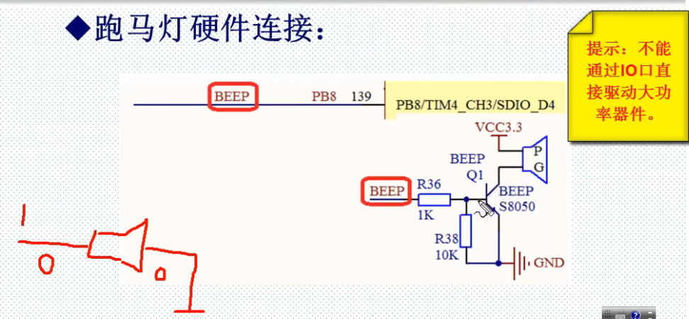
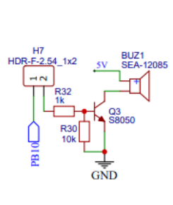
Recognize buzzer circuit
High power devices cannot be driven directly by IO port.
What is the function of NPN S8050 triode in the circuit?
10K function of triode base: when the default state of STM32 IO port is floating, a small current may be generated when the working state changes, which is amplified by the triode to make the buzzer sound. After adding 10K resistance, small current can be grounded.
Note: modify the experimental board into pbio port 10
Buzzer test steps
- Enable IO port clock. Call function RCC_APB2PeriphColckCmd(); Different IO groups call different clock enabling functions.
- Initialize IO port enable. Call function BEEP_Init();
- Operate the IO port to output high and low levels.
New file and code
Under the new project based on STM32F10x chip, create a new HARDWARE directory and a new beep h and beep c documents. Then put the c added to the directory h file specifies the path of the HARDWARE header file. Refer to the article "forerunner knowledge" for specific operation methods.
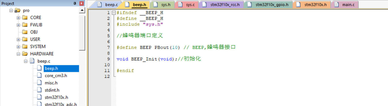
beep.h document code:
#ifndef __BEEP_H
#define __BEEP_H
#include "sys.h"

//Buzzer port definition

#define BEEP PBout(10) // BEEP, buzzer interface

void BEEP_Init(void);//initialization

#endif
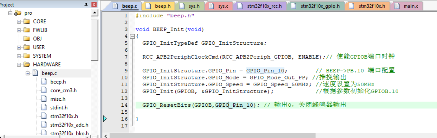
beep.c code:
#include "beep.h"

void BEEP_Init(void)
{
	GPIO_InitTypeDef GPIO_InitStructure;

	RCC_APB2PeriphClockCmd(RCC_APB2Periph_GPIOB, ENABLE);// Enable GPIOB port clock

	GPIO_InitStructure.GPIO_Pin = GPIO_Pin_10;        // BEEP->PB. 10 port configuration
	GPIO_InitStructure.GPIO_Mode = GPIO_Mode_Out_PP; //Push pull output
	GPIO_InitStructure.GPIO_Speed = GPIO_Speed_50MHz; //The speed is set to 50MHz
	GPIO_Init(GPIOB, &GPIO_InitStructure);            //Initialize gpiob according to parameters ten

	GPIO_ResetBits(GPIOB,GPIO_Pin_10); // Output 0, turn off buzzer output

}
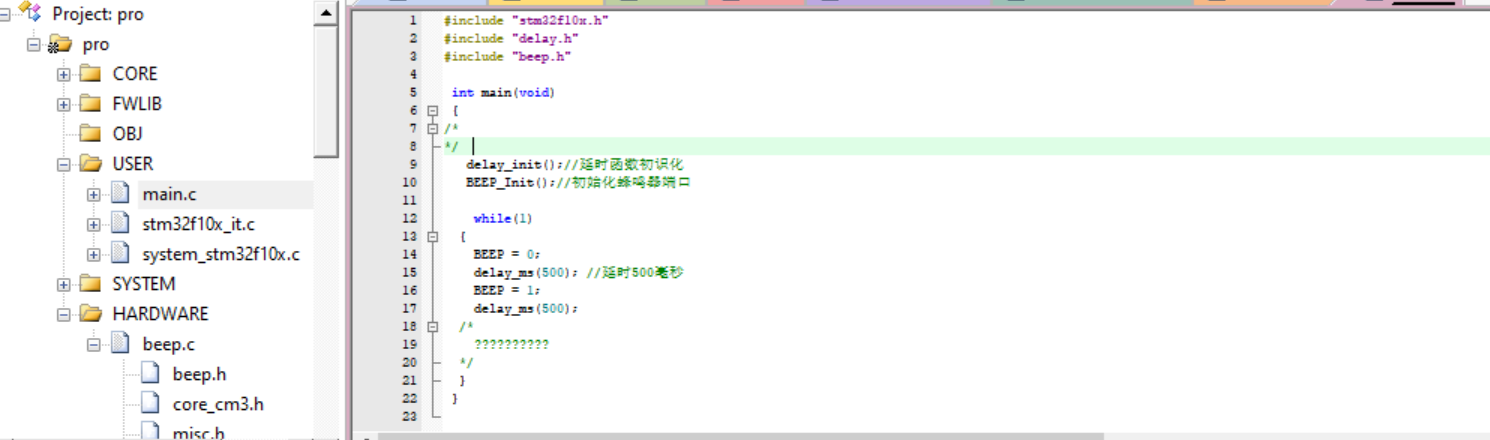
main.c document code:
#include "stm32f10x.h"
#include "delay.h"
#include "beep.h"

 int main(void)
 {
/*
*/
   delay_init();//Elementary knowledge of delay function
   BEEP_Init();//Initialize buzzer port

		while(1)
	{
		BEEP = 0;
		delay_ms(500); //500 ms delay
		BEEP = 1;
		delay_ms(500);
  /*
		??????????
  */
	}
 }