Leading knowledge
Multiplexing port function
What is port reuse?
STM32 has many built-in peripherals, and the external pins of these peripherals are multiplexed with GPIO. In other words, if a GPIO can be reused as the function pin of the built-in peripheral, when the GPIO is used as the built-in peripheral, it is called multiplexing.
Which port pins can be reused?
This part of knowledge is in STM32 Chinese reference manual V10 P109, P116~P121 explain in detail which GPIO pins can be reused for which built-in peripherals.
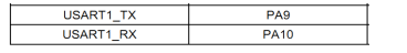
As we all know, MCU has serial ports, and STM32 has several serial ports. For example, STM32F103ZET6 has five serial ports. We can check the manual to know that the IO corresponding to the pin of serial port 1 is PA9 and PA10 The default function of PA9 and PA10 is GPIO, so when PA9 and PA10 pins are used as TX and Rx pins of serial port 1, that is port multiplexing.
There are three steps for multiplexing port initialization:
- GPIO port clock enable. To use port multiplexing, of course, it is necessary to enable the clock of the port.
RCC_APB2PeriphClockCmd(RCC_APB2Periph_GPIOA, ENABLE);
- Multiplexed peripheral clock enable. For example, you need to multiplex ports PA9 and PA10 into serial ports, so you need to enable the serial port clock.
RCC_APB2PeriphClockCmd(RCC_APB2Periph_USART1, ENABLE);
- Port mode configuration. When the peripheral function pin is built in the IO multiplexing bit, the GPIO port mode must be set. As for how the GPIO mode corresponds under the multiplexing function, please refer to the table "8.1.11 GPIO configuration of peripheral" in P110 of STM32 Chinese reference manual V10. Here we take Usart1 as an example:
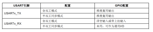
As can be seen from the table, if we want to configure full duplex serial port 1, the TX pin needs to be configured as push-pull multiplexed output, and the RX pin needs to be configured as floating input or with pull-up input.
//USART1_TX PA.9 multiplex push-pull output
GPIO_InitStructure.GPIO_Pin = GPIO_Pin_9; //PA.9
GPIO_InitStructure.GPIO_Speed = GPIO_Speed_50MHz;
GPIO_InitStructure.GPIO_Mode = GPIO_Mode_AF_PP; //Multiplex push-pull output
GPIO_Init(GPIOA, &GPIO_InitStructure);
//USART1_RX PA.10 floating input
GPIO_InitStructure.GPIO_Pin = GPIO_Pin_10;//PA10
GPIO_InitStructure.GPIO_Mode = GPIO_Mode_IN_FLOATING;//Floating input
GPIO_Init(GPIOA, &GPIO_InitStructure);
When using the multiplexing function, enable at least 2 clocks:
-
GPIO clock enable
-
Multiplexed peripheral clock enable
For example:
RCC_APB2PeriphClockCmd(RCC_APB2Periph_USART1|RCC_APB2Periph_GPIOA, ENABLE); //Enable USART1, GPIOA clock
Port remapping
What is port remapping?
In order to optimize the number of peripheral IO functions in different device packages, some multiplexing functions can be remapped to other pins.
In STM32, the input and output pins of many built-in peripherals have the function of remap. We know that each built-in peripheral has several input and output pins. Generally, the output ports of these pins are fixed. In order to enable the design engineer to better arrange the direction and function of the pins, the concept of peripheral pin remapping is introduced in STM32, that is, the pin of a peripheral has a default port, The pin of this peripheral can also be mapped to other ports by setting the remapping register.
In short, it is to map the peripheral function of a pin to another pin, but it can not be mapped casually. The specific correspondence is explained in "8.3 multiplexing function and debugging configuration" on page P116 of STM32 Chinese reference manual V10. Here we also take serial port 1 as an example.
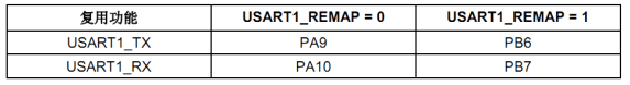
As can be seen from the table, by default, the pin bits PA9 and PA10 when serial port 1 is multiplexed. At the same time, we can remap TX and RX to pins PB6 and PB7.
Therefore, for remapping, we also need to enable the AFIO function clock in addition to the two clocks explained when reusing the function, and then call the remapping function.
The four detailed steps are:
- Enable GPIOB clock
RCC_APB2PeriphClockCmd(RCC_APB2Periph_GPIOB, ENABLE);
- Enable serial port 1 clock
RCC_APB2PeriphClockCmd(RCC_APB2Periph_USART1, ENABLE);
- Enable AFIO (multiplex IO) clock
RCC_APB2PeriphClockCmd(RCC_APB2Periph_AFIO, ENABLE);
- Turn on remapping function
GPIO_PinRemapConfig(GPIO_Remap_USART1, ENABLE);
In this way, the TX and RX of the serial port are remapped to pins PB6 and PB7.
As for what functions can be remapped, in addition to viewing the Chinese reference manual, you can also use GPIO_ Starting with the pinremapconfig function, you can see the value range of the first entry parameter. In stm32f10x_gpio.h file defines the identifier whose value range is defined by the following macro. Here we post a small part:
#define GPIO_Remap_SPI1 ((uint32_t)0x00000001)
#define GPIO_Remap_I2C1 ((uint32_t)0x00000002)
#define GPIO_Remap_USART1 ((uint32_t)0x00000004)
#define GPIO_Remap_USART2 ((uint32_t)0x00000008)
#define GPIO_PartialRemap_USART3 ((uint32_t)0x00140010)
#define GPIO_FullRemap_USART3 ((uint32_t)0x00140030)
As can be seen from the above, USART1 has only one remapping, while for USART3, there are partial remapping and complete remapping.
The so-called partial remapping means that some pins are the same as the default, and some pins are remapped to other pins. Full remapping means that all pins are remapped to other pins.
Look at the USART3 remapping table in the manual:
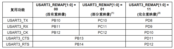
Partial remapping means that pb10, pb11 and pb12 are remapped to PC10,PC11 and PC12.
PB13 and PB14 are the same as those without remapping. They are USART3_CTS and USART3_RTS corresponding pin. Complete remapping is to remap these two feet to PD11 and PD12.
To use the partial remapping of USART3, we call the function method as follows:
GPIO_PinRemapConfig(GPIO_PartialRemap_USART3, ENABLE);
NVIC interrupt priority management
What is NVIC?
"The full name of NVIC is nested vector interrupt controller, that is, nested vector interrupt controller."
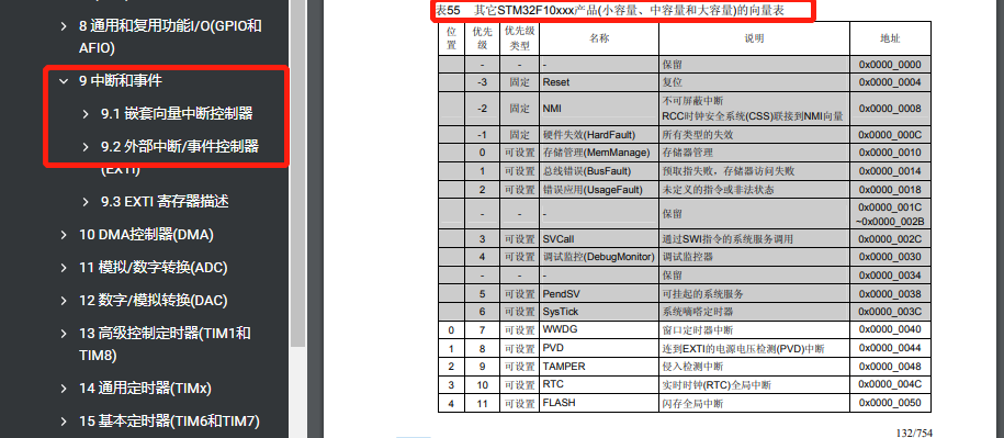
The CM3 kernel supports 256 interrupts, including 16 kernel interrupts and 240 external interrupts, and has 256 levels of programmable interrupt settings. However, STM32 does not use all things of CM3 kernel, but only a part of it.
STM32 has 84 interrupts, including 16 kernel interrupts and 68 maskable interrupts, with 16 levels of programmable interrupt priority. (in the vector table of interconnected products and other STM32F10xxx products: there are only 68 in 107 Series).
We often use these 68 maskable interrupts (external interrupts), but the 68 maskable interrupts of STM32 have only 60 external interrupts in STM32F103 series.
Because the chip selected by our development board is STM32F103 series, we only introduce the 60 maskable interrupts of STM32F103 series.
In the MDK, the following structures are defined for registers related to NVIC:
typedef struct
{
 __IO uint32_t ISER[8]; /*!< Interrupt Set Enable Register */
 uint32_t RESERVED0[24];
 __IO uint32_t ICER[8]; /*!< Interrupt Clear Enable Register */
 uint32_t RSERVED1[24];
 __IO uint32_t ISPR[8]; /*!< Interrupt Set Pending Register */
 uint32_t RESERVED2[24];
 __IO uint32_t ICPR[8]; /*!< Interrupt Clear Pending Register */
 uint32_t RESERVED3[24];
 __IO uint32_t IABR[8]; /*!< Interrupt Active bit Register */
 uint32_t RESERVED4[56];
 __IO uint8_t IP[240]; /*!< Interrupt Priority Register, 8Bit wide */
 uint32_t RESERVED5[644];
 __O uint32_t STIR; /*!< Software Trigger Interrupt Register */
} NVIC_Type;
The interrupts of STM32 are executed orderly under the control of these registers. Only by understanding these interrupt registers can we easily use the interrupt of STM32. The following focuses on these registers:
- ISER[8]: the full name of ISER is interrupt set enable registers, which is an interrupt enable register group. As mentioned above, the CM3 kernel supports 256 interrupts, which are controlled by 8 32-bit registers, and each bit controls one interrupt. However, STM32F103 has only 60 maskable interrupts, so for us, two (ISER[0] and ISER[1]) are useful, which can represent 64 interrupts in total. STM32F103 only uses the first 60 bits. bit0~bit31 of ISER[0] correspond to interrupt 0 ~ 31 respectively. bit0~27 of ISER[1] corresponds to interrupt 32 ~ 59; In this way, a total of 60 interrupts correspond to each other. If you want to enable an interrupt, you must set the corresponding ISER bit to 1 to enable the interrupt (here is only enable, and it is a complete interrupt setting in combination with interrupt grouping, shielding, IO port mapping and other settings). For the specific interrupt corresponding to each bit, please refer to stm32f10x H (for compiler MDK5).
- ICER[8]:
- ISPR[8]:
- ICPR[8]:
- IABR[8]:
- IP[240]:
Interrupt priority grouping
- Group: 5
- Interruption per group: 12
- External interrupt: 60 in total
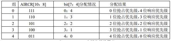
Here is a brief introduction to the interrupt grouping of STM32: STM32 divides interrupts into 5 groups, groups 0 ~ 4. The setting of this packet is defined by bit10~8 of SCB - > aircr register.
explain:
- Aircr [10: 8] represents 3 bits to select the number of interrupt groups. For example, 110 represents the first group of interrupts.
- bit[7: 4] indicates that 4 is the setting allocation. For example, [0: 4] indicates [0-bit preemption priority, 4-bit response priority]
Through this table, we can clearly see the configuration relationship corresponding to groups 0 ~ 4. For example, if the group is set to 3, then
For all 60 interrupts, the highest 3 bits in the upper 4 bits of the interrupt priority register of each interrupt are preemptive priority, and the lower 1 bit is preemptive priority
Response priority. For each interrupt, you can set the preemption priority to 0 ~ 7 and the response priority to 1 or 0. Preemptive priority
The level is higher than the response priority. The smaller the value, the higher the priority.
Preemption priority & response priority difference:
-
The preemption priority of high priority can interrupt the ongoing interruption of low preemption priority. A is the governor and B is the mayor
-
For interrupts with the same preemptive priority, the response priority of high priority cannot interrupt the interrupt of low response priority. BB is the municipal level, C is the severity of the matter, and D is not an urgent matter.
-
For interrupts with the same preemptive priority, when two interrupts occur at the same time, the response priority is high, and it will be executed first. BB are all mayors and CC are at the same level
-
If the preemption priority and response priority of two interrupts are the same, whichever interrupt occurs first will be executed first. [A:A] [ A:A]
Examples are as follows:
Suppose the interrupt priority group is set to: 2
The preemptive priority of interrupt 3 (RTC interrupt) is 2 and the response priority is 1.
The preemption priority of interrupt 6 (external interrupt 0) is: 3, and the response priority is: 0.
The preemption priority of interrupt 7 (external interrupt 1) is: 2, and the response priority is: 0.
Then the priority order of the three interrupts is: interrupt 7 > interrupt 3 > interrupt 6.
Note: the smaller the value, the higher the priority. After setting the grouping, do not change the grouping at will, which will lead to confusion of interrupt management.
Interrupt priority setting
Through the above introduction, we are familiar with the general process of STM32 interrupt setting. Next, we introduce how to use the library function to realize the above interrupt grouping setting and interrupt priority management, so as to simplify our interrupt setting in the future. NVIC interrupt management function is mainly in misc C in the document.
Interrupt priority grouping function NVIC_PriorityGroupConfig
void NVIC_PriorityGroupConfig(uint32_t NVIC_PriorityGroup);
- Parameter: NVIC_PriorityGroup
- NVIC_PriorityGroup_0
- NVIC_PriorityGroup_1
- NVIC_PriorityGroup_2
- NVIC_PriorityGroup_3
- NVIC_PriorityGroup_4
This function is used to group the priority of interrupts. This function can only be called once in the system. Once the grouping is determined, it's best not to change it.
For example, if we set the interrupt priority grouping value of the whole system to 2, the method is:
NVIC_PriorityGroupConfig(NVIC_PriorityGroup_2);
In this way, a total of "2-bit preemption priority and 2-bit response priority" is determined.

How to set the preemption priority and response priority of a single interrupt after confirming the grouping???
Interrupt initialization function NVIC_Init
NVIC_Init, whose function is declared as:
void NVIC_Init(NVIC_InitTypeDef* NVIC_InitStruct)
Including NVIC_InitTypeDef is a structure. We can see the member variables of the structure:
typedef struct
{
 uint8_t NVIC_IRQChannel;
 uint8_t NVIC_IRQChannelPreemptionPriority;
 uint8_t NVIC_IRQChannelSubPriority;
 FunctionalState NVIC_IRQChannelCmd;
 } NVIC_InitTypeDef;
NVIC_ There are three member variables in the middle of inittypedef structure. The functions of these three member variables are:
- NVIC_IRQChannel: defines which interrupt is initialized. This can be found in stm32f10x Find the name corresponding to each interrupt in H. For example, USART1_IRQn. As follows:
  WWDG_IRQn                   = 0,      /*!< Window WatchDog Interrupt                            */
  PVD_IRQn                    = 1,      /*!< PVD through EXTI Line detection Interrupt            */
  TAMPER_IRQn                 = 2,      /*!< Tamper Interrupt                                     */
  RTC_IRQn                    = 3,      /*!< RTC global Interrupt                                 */
  FLASH_IRQn                  = 4,      /*!< FLASH global Interrupt                               */
  RCC_IRQn                    = 5,      /*!< RCC global Interrupt                                 */
  EXTI0_IRQn                  = 6,      /*!< EXTI Line0 Interrupt                                 */
  EXTI1_IRQn                  = 7,      /*!< EXTI Line1 Interrupt                                 */
  EXTI2_IRQn                  = 8,      /*!< EXTI Line2 Interrupt                                 */
  EXTI3_IRQn                  = 9,      /*!< EXTI Line3 Interrupt                                 */
  EXTI4_IRQn                  = 10,     /*!< EXTI Line4 Interrupt                                 */
  DMA1_Channel1_IRQn          = 11,     /*!< DMA1 Channel 1 global Interrupt                      */
  DMA1_Channel2_IRQn          = 12,     /*!< DMA1 Channel 2 global Interrupt                      */
  DMA1_Channel3_IRQn          = 13,     /*!< DMA1 Channel 3 global Interrupt                      */
  DMA1_Channel4_IRQn          = 14,     /*!< DMA1 Channel 4 global Interrupt                      */
  DMA1_Channel5_IRQn          = 15,     /*!< DMA1 Channel 5 global Interrupt                      */
  DMA1_Channel6_IRQn          = 16,     /*!< DMA1 Channel 6 global Interrupt                      */
  DMA1_Channel7_IRQn          = 17,     /*!< DMA1 Channel 7 global Interrupt                      */
- NVIC_IRQChannelPreemptionPriority: defines the preemption priority of this interrupt.
- NVIC_IRQChannelSubPriority: defines the sub priority of this interrupt.
- NVIC_IRQChannelCmd: whether the interrupt is enabled.
For example:
	NVIC_InitTypeDef NVIC_InitStructure;
   //Usart1 NVIC configuration
    NVIC_InitStructure.NVIC_IRQChannel = USART1_IRQn;//Serial port 1 interrupt
	NVIC_InitStructure.NVIC_IRQChannelPreemptionPriority=3 ;//Preemption priority 3
	NVIC_InitStructure.NVIC_IRQChannelSubPriority = 3;		//Sub priority 3
	NVIC_InitStructure.NVIC_IRQChannelCmd = ENABLE;			//IRQ channel enable
	NVIC_Init(&NVIC_InitStructure);	//Initializes the VIC register according to the specified parameters
summary
Summarize the steps of interrupt priority setting:
-
1. Set interrupt group at the beginning of system operation. Determine the group number, that is, determine the allocation number of preemptive priority and sub priority. The calling function is NVIC_PriorityGroupConfig();
-
2. Set the interrupt priority of the interrupt used. The function called for each interrupt is NVIC_Init();
External interrupt
Each IO of STM32 can be used as an interrupt input port for external interrupts, which is also the strength of STM32. The interrupt controller of STM32F103 supports 19 external interrupt / event requests. Each interrupt is equipped with status bits, and each interrupt / event has independent trigger and mask settings.
The 19 external interrupts of STM32F103 are:
- Line 0 ~ 15: input interrupt corresponding to external IO port. (16)
- Line 16: connected to PVD output. (1)
- Line 17: connect to RTC alarm events. (1)
- Line 18: connect to USB wake-up event. (1)
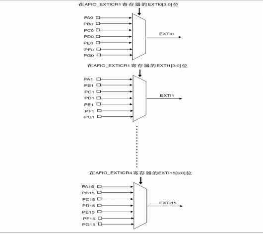
It can be seen from the above that STM32 has only 16 interrupt lines for IO ports, but STM32 has far more than 16 IO ports. So how does STM32 correspond the 16 interrupt lines to IO ports one by one?
So STM32 is designed in this way. The pin of GPIO is gpiox 0~GPIOx. 15 (x = a, B, C, D, e, F,G) correspond to interrupt lines 0 ~ 15 respectively. In this way, each interrupt line corresponds to up to 7 IO ports.
Take line 0 as an example: it corresponds to gpioa 0,GPIOB.0,GPIOC.0,GPIOD.0,GPIOE.0,GPIOF.0,GPIOG.0
The medium break line can only be connected to one IO port at a time, so it is necessary to determine which GPIO the corresponding break line is configured to through configuration. Let's take a look at the mapping relationship between GPIO and interrupt line:
Initialize IO port as input
Turn on AFIO clock
Set the mapping relationship between interrupt line and GPIO
Set initialization parameters such as trigger mode of interrupt
Set NVIC interrupt priority
Write interrupt service function
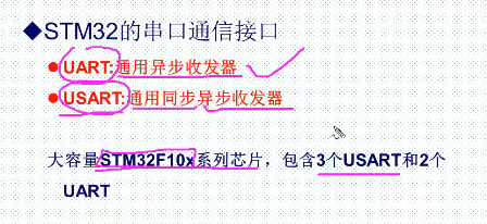
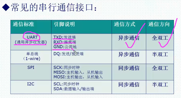
Serial communication
STM32F103ZET6 can provide up to 5 serial ports: 3 USART universal synchronous asynchronous transceivers and 2 UART universal asynchronous transceivers.
Serial communication interface background
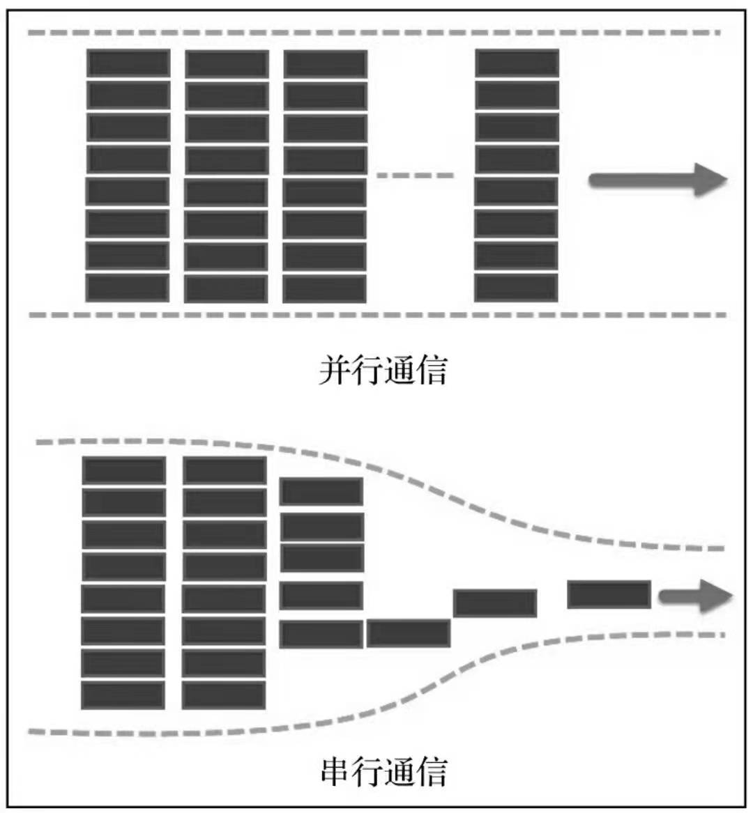
Serial communication and parallel communication
There are two ways for the processor to communicate with external devices:
-
Parallel communication
-
serial communication
According to the way of data transmission, communication can be divided into serial communication and parallel communication.
Serial communication refers to the communication mode of transmitting data bit by bit in the form of data bits between devices through a small number of data signal lines (generally less than 8), ground wires and control signal lines. Parallel communication generally refers to the communication mode of simultaneous transmission using 8, 16, 32 and 64 or more data lines.
Parallel communication is like a multi lane highway, which can transmit data of multiple data bits at the same time, while serial communication is like a single lane highway, which can only transmit data of one data bit at the same time.
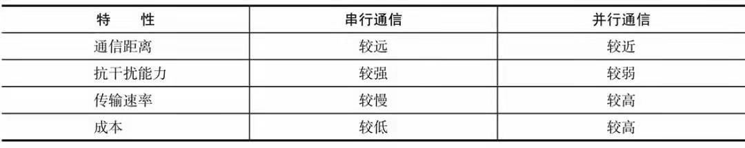
Comparison of the two characteristics:
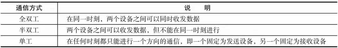
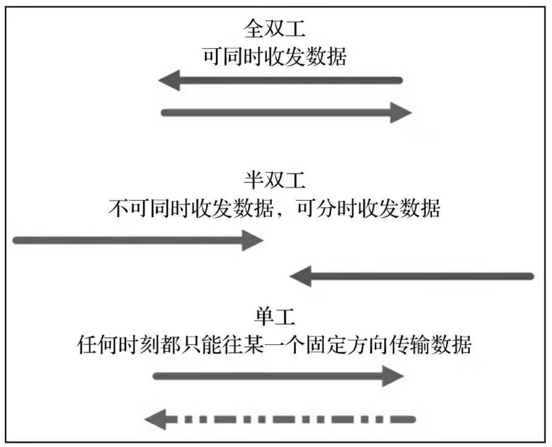
Full duplex, half duplex and simplex communication
According to the direction of data communication, communication is divided into full duplex, half duplex and simplex communication, which are mainly distinguished by the direction of channel.
Still use the road analogy:
- Full duplex communication is a two-way lane, and the traffic flow in the two directions is irrelevant to each other;
- Half duplex is like a country road. At the same time, only one car can pass through, and cars from the other direction can only pass when the road is empty;
- Simplex work is like a one-way street, and vehicles in the other direction are completely prohibited.
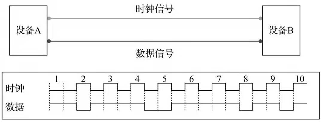
Synchronous communication and asynchronous communication
Synchronous communication: synchronous signal transmission with clock (I2C, SPI)
Asynchronous communication: without clock synchronization signal (UART)
According to the data synchronization mode of communication, it is divided into synchronous and asynchronous, which can be simply distinguished according to whether the clock signal is used in the communication process.
In synchronous communication, both sides of the transceiver will use a signal line as the clock signal. Driven by the clock signal, both sides coordinate and synchronize data. In communication, both parties usually uniformly stipulate to sample the data line on the rising or falling edge of the clock signal.
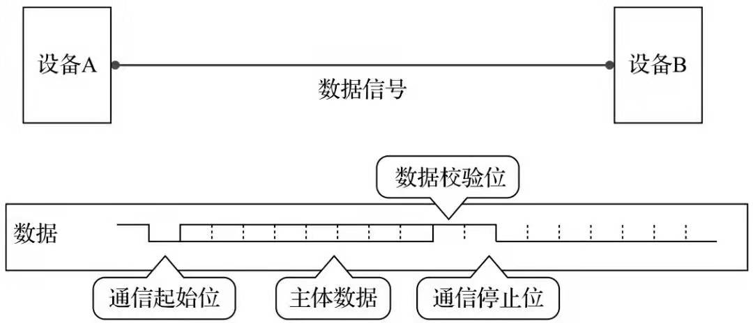
In asynchronous communication, the clock signal is not used for data synchronization. They directly insert some signal bits for synchronization in the data signal, or package the main data and transmit the data in the format of data frame. In some communications, both parties need to agree on the data transmission rate (bit rate) in order to better synchronize.
Differences between the two:
1. In synchronous communication, most of the contents transmitted by data signals are valid data, while asynchronous communication will contain various identifiers of frames, so the efficiency of synchronous communication is higher.
2. The allowable clock error of synchronous communication is small, while that of asynchronous communication is large.
Communication rate (bit rate)
A very important parameter to measure the communication performance is the communication rate, which is usually expressed in bit rate, that is, the number of bits transmitted per second, in bits per second (bit/s).
The concept easily confused with bit rate is baud rate, which indicates how many symbols are transmitted per second.
Symbol is the concept of communication signal modulation. In communication, symbols with the same time interval are often used to represent a binary number. Such a signal is called symbol.
For example, in common communication transmission, 0V represents the number 0 and 5V represents the number 1, then a symbol can represent two states 0 and 1, so a symbol is equal to a binary bit, and the baud rate is consistent with the bit rate at this time; If the binary numbers 00, 01, 10 and 11 are represented by 0V, 2V, 4V and 6V respectively in communication transmission, each symbol can represent four states, that is, two binary bits, so the number of symbols is half of the number of binary bits, and the baud rate at this time is half of the bit rate.
Because a symbol in common communication represents two states, people often express the bit rate directly by baud rate. Although there are no mistakes strictly speaking, we can understand the difference between them.
Communication process
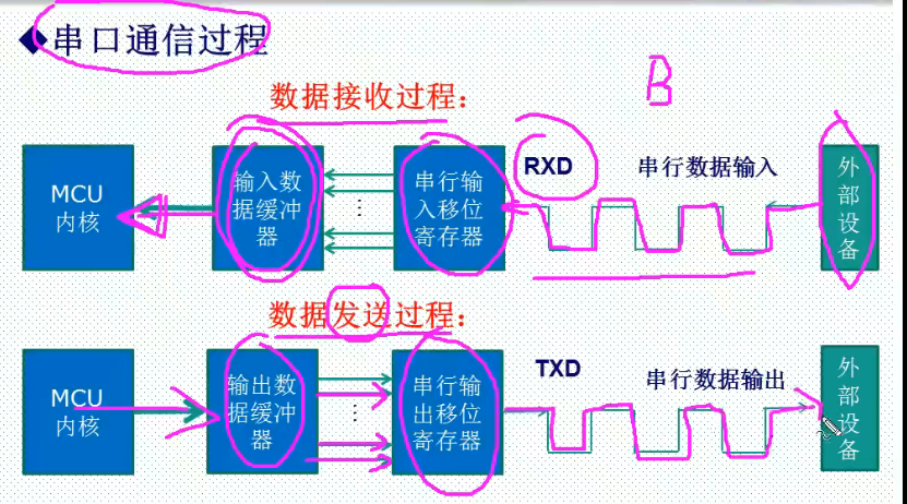
Parameters to be defined
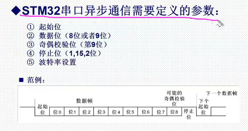
STM32F1 serial port frame diagram
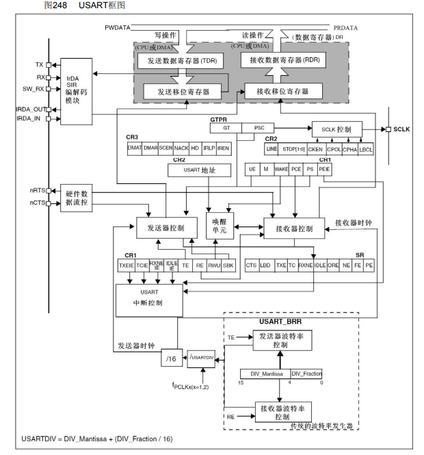
Common registers and library functions of STM32 serial port
- Status register USART_SR
- Data register USART_DR
- Baud ratio register USART_BRR
- Control register 1 USART_CR1
- Control register 2 USART_CR2
- Control register 3 USART_CR3
- Protection time and prescaler register USART_GTPR
Baud rate calculation
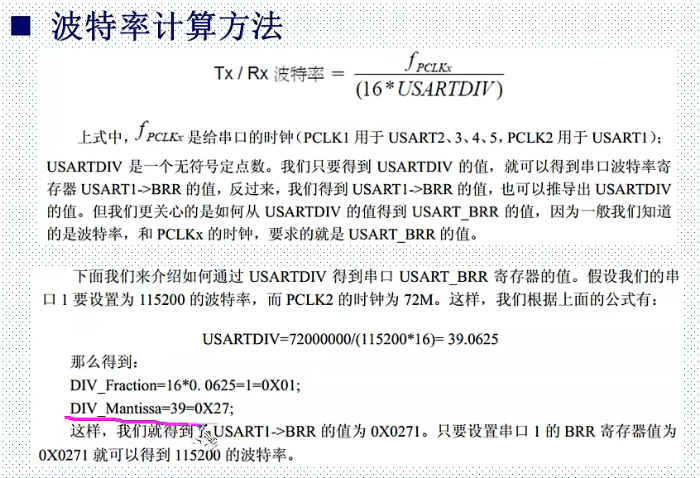
Serial port clock PCLK1 (USART2, 3, 4, 5), pclk2 (usart1)
Integer part 39
Decimal part needs to be "multiplied by 16"
Serial port operation function
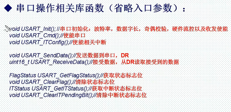
In stm32f10x_usart.h header file to view related functions.
-
void USART_Init(USART_TypeDef* USARTx,USART_InitTypeDef* USART_InitStruct) / / create library parameters, initialization baud rate, word length, stop bit, parity bit, hardware data flow control, mode (receive, send)
-
USART_Cmd(USART1, ENABLE); // Enable serial port
-
void USART_ Itconfig (usart_typedef * usartx, uint16_t usart_it, functionalstate, newstate) / / function that enables serial port interrupt
-
void USART_ SendData(USART_TypeDef* USARTx, uint16_t Data); // USART_ Send data to Dr register
-
uint16_ t USART_ ReceiveData(USART_TypeDef* USARTx);// USART_ The Dr register reads the data received by the serial port
-
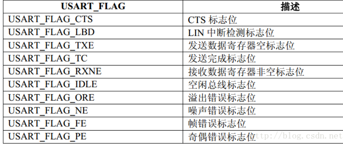
FlagStatus USART_GetFlagStatus(USART_TypeDef* USARTx, uint16_t USART_FLAG);// USART_SR register reads serial port status flag bit
-
void USART_ClearFlag(USART_TypeDef* USARTx, uint16_t USART_FLAG);// Clear status flag bit
-
ITStatus USART_GetITStatus(USART_TypeDef* USARTx, uint16_t USART_IT)//USART_CR register obtains the interrupt status flag bit (but the flag bit needs to be cleared after the serial port triggers the interrupt)
-
void USART_ClearITPendingBit(USART_TypeDef* USARTx, uint16_t USART_IT);// Clear interrupt flag bit
Serial port configuration method and communication example
Serial port experiment
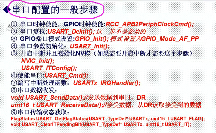
1) Serial port clock enable, GPIO clock enable
New void uart_init(u32 bound) function. The parameter bound is the baud rate.
Creating a custom UART_ Execute in init function:
RCC_APB2PeriphClockCmd(RCC_APB2Periph_USART1|RCC_APB2Periph_GPIOA, ENABLE); //Enable USART1, GPIOA clock
2) Serial port reset
slightly
3) GPIO port mode setting
Creating a custom UART_ Execute in init function:
  GPIO_InitTypeDef GPIO_InitStructure; // Structure variable

	//USART1_TX   GPIOA.9
  GPIO_InitStructure.GPIO_Pin = GPIO_Pin_9; //PA.9
  GPIO_InitStructure.GPIO_Speed = GPIO_Speed_50MHz;
  GPIO_InitStructure.GPIO_Mode = GPIO_Mode_AF_PP;	//Multiplex push-pull output
  GPIO_Init(GPIOA, &GPIO_InitStructure);//Initialize gpioa nine

  //USART1_RX 	   GPIOA.10 initialization
  GPIO_InitStructure.GPIO_Pin = GPIO_Pin_10;//PA10
  GPIO_InitStructure.GPIO_Mode = GPIO_Mode_IN_FLOATING;//Floating input
  GPIO_Init(GPIOA, &GPIO_InitStructure);//Initialize gpioa ten
Note: GPIO of serial port 1_ Pin_ 9 and GPIO_Pin_10. The output mode setting is specified in the following table. The output port is set as push-pull multiplex output, and the input port is set as pull-up / floating input.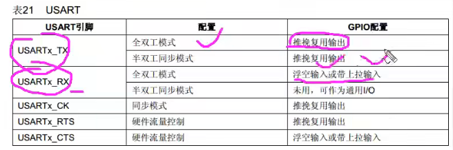
Another configuration method is introduced as follows:
	GPIO_InitStructure.GPIO_Pin = GPIO_Pin_9 | GPIO_Pin_10; //GPIOA9 and GPIOA10
	GPIO_InitStructure.GPIO_Mode = GPIO_Mode_AF;//Reuse function
	GPIO_InitStructure.GPIO_Speed = GPIO_Speed_50MHz;	//Speed 50MHz
	GPIO_InitStructure.GPIO_OType = GPIO_OType_PP; //Push pull multiplex output
	GPIO_InitStructure.GPIO_PuPd = GPIO_PuPd_UP; //Pull up
	GPIO_Init(GPIOA,&GPIO_InitStructure); //Initialize PA9, PA10
4) Serial port parameter initialization
Creating a custom UART_ Execute in init function:
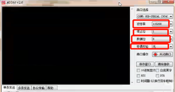
Note: the parameters of both sides of serial communication should be consistent
	USART_InitTypeDef USART_InitStructure; //
	   //USART initialization settings

   //USART initialization settings

	USART_InitStructure.USART_BaudRate = bound;//Serial port baud rate 115200 9600
	USART_InitStructure.USART_HardwareFlowControl = USART_HardwareFlowControl_None;//No hardware data flow control
	USART_InitStructure.USART_Mode = USART_Mode_Rx | USART_Mode_Tx;	//Both receive and send modes are enabled
	USART_InitStructure.USART_Parity = USART_Parity_No;//No parity bit
	USART_InitStructure.USART_StopBits = USART_StopBits_1;//A stop bit
	USART_InitStructure.USART_WordLength = USART_WordLength_8b;//The word length is in 8-bit data format
    USART_Init(USART1, &USART_InitStructure); //Initialize serial port 1
5) Turn on the interrupt and initialize the NVIC (this step is required if the interrupt needs to be turned on)
main.c set the interrupt group as: 2
NVIC_PriorityGroupConfig(NVIC_PriorityGroup_2); //Set NVIC interrupt packet 2: 2-bit preemption priority and 2-bit response priority
Creating a custom UART_ Execute in init function:
USART_ITConfig(USART1, USART_IT_RXNE, ENABLE);//Open serial port 1 interrupt type: accepting interrupt enable means that the interrupt service function is executed when the data is received
Creating a custom UART_ Execute in init function:
Set interrupt priority
    NVIC_InitTypeDef NVIC_InitStructure;// Structure pointer variable
	//Usart1 NVIC configuration
    NVIC_InitStructure.NVIC_IRQChannel = USART1_IRQn; //
	NVIC_InitStructure.NVIC_IRQChannelPreemptionPriority=3 ;//Preemption priority 3
	NVIC_InitStructure.NVIC_IRQChannelSubPriority = 3;		//Sub priority 3
	NVIC_InitStructure.NVIC_IRQChannelCmd = ENABLE;			//IRQ channel enable
	NVIC_Init(&NVIC_InitStructure);	//Initializes the VIC register according to the specified parameters
6) Enable serial port
USART_Cmd(USART1, ENABLE); //Enable serial port 1
7) Write interrupt handling function
First, create a new void USART1_IRQHandler(void) function.
void USART1_IRQHandler(void)                	//Serial port 1 interrupt service program
	{}
8) Serial port data transceiver
USART_GetITStatus(USART1, USART_IT_RXNE) function
Function: the receive interrupt function returns 1 to indicate the received data (the received data must be 0x0D and 0x0a at the end)
Parameters:
- Entry parameter 1: Interrupt / / USART1
- Entry parameter 2 type / / receive interrupt (the received data must end in 0x0D and 0x0a)
USART_ReceiveData(USART1) function
Function: read received data
Parameter: interrupt source USART1
USART_SendData function
Function: MCU sends data to serial port
Parameters:
- Entry parameter 1 serial port number USARTx
- Entry parameter 2 data
void USART1_IRQHandler(void)                	//Serial port 1 interrupt service program
	{
	u8 Res;

	if(USART_GetITStatus(USART1, USART_IT_RXNE))  //Receive interrupt (the received data must end in 0x0D and 0x0a) typedef enum {reset = 0, set =! Reset} flagstatus, itstatus;
		{
		Res =USART_ReceiveData(USART1);	//Read received data = = Res
		USART_SendData(USART1,Res); //Send received data to serial port 1 = = Res
		// Note that both sending and receiving are Res

     }

}
9) Serial port transmission status acquisition
Reference article: Study notes - USART of STM32_ Getflagstatus and USART_GetITStatus parsing
USART_GetFlagStatus() function
Function: get status Flag flag bit
USART_ClearITPendingBit() function
Function: clear status Flag flag bit
USART_GetITStatus() function
Function: get the interrupt status flag bit
Example: USART_GetITStatus(USART1, USART_IT_RXNE)
Function: read serial port status flag bit (USART_SR register)
Parameters:
- Entry parameter 1 serial ports USART1,USART2,USART3,UART4,UART5
- Entry parameter 2 receive interrupt USART_IT_RXNE (other parameters are as follows)
USART_ClearITPendingBit() function
Function: clear the interrupt status flag bit
summary
It deepens the basic theoretical knowledge of single-chip communication. The interrupt in the experiment can be avoided, so there is no need to assign interrupt priority and other operations.
Note: the parameter settings of the serial port debugging assistant are consistent with the serial port initialization parameters.
expand:
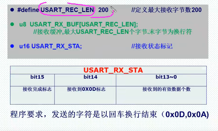
extern u16 USART_RX_STA; Receive status flag carriage return 0x0D received data line feed 0x0A
uart.h
#ifndef __USART_H
#define __USART_H
#include "stdio.h"
#include "sys.h"
//V1.4 Modification Description
//1. Modify the bug of serial port initialization IO
//2. Modified USART_RX_STA, so that the maximum number of bytes received by the serial port is the 14th power of 2
//3. USART is added_ REC_ Len, used to define the maximum number of bytes allowed to be received by the serial port (not greater than the 14th power of 2)
//4. Modified EN_USART1_RX enable mode
//V1.5 Modification Description
//1. Added support for UCOSII
#define USART_REC_LEN   			 two hundred 	// Define the maximum number of bytes received 200
#define EN_USART1_RX  			    one 		// Enable (1) / disable (0) serial port 1 reception

extern u8  USART_RX_BUF[USART_REC_LEN];  //Receive buffer, maximum USART_REC_LEN bytes The last byte is a newline character
extern u16 USART_RX_STA;         		     Receive status flag	enter==0x0D  Received data wrap==0x0A
//If you want to interrupt reception through the serial port, please do not comment on the following macro definitions
void uart_init(u32 bound);
#endif
The program requires that the sent character / received data must be 0x0D (end of 0x0a)
uart.c
#include "sys.h"
#include "usart.h"

//Add the following code to support the printf function without selecting use MicroLIB
#if 1
#pragma import(__use_no_semihosting)
//Support functions required by the standard library
struct __FILE
{
	int handle;

};

FILE __stdout;
//Definition_ sys_exit() to avoid using half host mode
void _sys_exit(int x)
{
	x = x;
}
//Redefine fputc function
int fputc(int ch, FILE *f)
{
	while((USART1->SR&0X40)==0);//Send circularly until sending is completed
    USART1->DR = (u8) ch;
	return ch;
}
#endif

/*Method using microLib*/
 /*
int fputc(int ch, FILE *f)
{
	USART_SendData(USART1, (uint8_t) ch);

	while (USART_GetFlagStatus(USART1, USART_FLAG_TC) == RESET) {}

    return ch;
}
int GetKey (void)  {

    while (!(USART1->SR & USART_FLAG_RXNE));

    return ((int)(USART1->DR & 0x1FF));
}
*/

#if EN_USART1_RX / / if receive is enabled
//Serial port 1 interrupt service program
//Note that reading usartx - > SR can avoid inexplicable errors
u8 USART_RX_BUF[USART_REC_LEN];     //Receive buffer, maximum USART_REC_LEN bytes
//Receiving status
//bit15, 	 Reception completion flag
//bit14, 	 0x0d received
//bit13~0, 	 Number of valid bytes received
u16 USART_RX_STA=0;       //Receive status flag

void uart_init(u32 bound){
  //GPIO port settings
  GPIO_InitTypeDef GPIO_InitStructure;
	USART_InitTypeDef USART_InitStructure;
	NVIC_InitTypeDef NVIC_InitStructure;

	RCC_APB2PeriphClockCmd(RCC_APB2Periph_USART1|RCC_APB2Periph_GPIOA, ENABLE);	//Enable USART1, GPIOA clock

	//USART1_TX   GPIOA.9
  GPIO_InitStructure.GPIO_Pin = GPIO_Pin_9; //PA.9
  GPIO_InitStructure.GPIO_Speed = GPIO_Speed_50MHz; // Speed is not required
  GPIO_InitStructure.GPIO_Mode = GPIO_Mode_AF_PP;	//Multiplex push-pull output
  GPIO_Init(GPIOA, &GPIO_InitStructure);//Initialize gpioa nine

  //USART1_RX 	   GPIOA.10 initialization
  GPIO_InitStructure.GPIO_Pin = GPIO_Pin_10;//PA10
  GPIO_InitStructure.GPIO_Mode = GPIO_Mode_IN_FLOATING;//Floating input
  GPIO_Init(GPIOA, &GPIO_InitStructure);//Initialize gpioa ten


   //USART initialization settings

	USART_InitStructure.USART_BaudRate = bound;//Serial port baud rate 115200 9600
	USART_InitStructure.USART_HardwareFlowControl = USART_HardwareFlowControl_None;//No hardware data flow control
	USART_InitStructure.USART_Mode = USART_Mode_Rx | USART_Mode_Tx;	//Both receive and send modes are enabled
	USART_InitStructure.USART_Parity = USART_Parity_No;//No parity bit
	USART_InitStructure.USART_StopBits = USART_StopBits_1;//A stop bit
	USART_InitStructure.USART_WordLength = USART_WordLength_8b;//The word length is in 8-bit data format
  USART_Init(USART1, &USART_InitStructure); //Initialize serial port 1


  USART_Cmd(USART1, ENABLE);                    //Enable serial port 1

	USART_ITConfig(USART1, USART_IT_RXNE, ENABLE);//Open serial port to accept interrupt

	//Usart1 NVIC configuration
  NVIC_InitStructure.NVIC_IRQChannel = USART1_IRQn;
	NVIC_InitStructure.NVIC_IRQChannelPreemptionPriority=3 ;//Preemption priority 3
	NVIC_InitStructure.NVIC_IRQChannelSubPriority = 3;		//Sub priority 3
	NVIC_InitStructure.NVIC_IRQChannelCmd = ENABLE;			//IRQ channel enable
	NVIC_Init(&NVIC_InitStructure);	//Initializes the VIC register according to the specified parameters

}

void USART1_IRQHandler(void)                	//Serial port 1 interrupt service program
	{
	u8 Res;
#if SYSTEM_SUPPORT_OS  		// If system_ SUPPORT_ If OS is true, you need to support OS
	OSIntEnter();
#endif
	if(USART_GetITStatus(USART1, USART_IT_RXNE) != RESET)  //Receive interrupt (the received data must end in 0x0D and 0x0a) typedef enum {reset = 0, set =! Reset} flagstatus, itstatus;
		{
		Res =USART_ReceiveData(USART1);	//Read received data

		if((USART_RX_STA&0x8000)==0)//Reception incomplete
			{
			if(USART_RX_STA&0x4000)//0x0d received
				{
				if(Res!=0x0a)USART_RX_STA=0;//Error, restart receiving
				else USART_RX_STA|=0x8000;	//Reception is complete
				}
			else //I haven't received 0X0D yet
				{
				if(Res==0x0d)USART_RX_STA|=0x4000;
				else
					{
					USART_RX_BUF[USART_RX_STA&0X3FFF]=Res ;
					USART_RX_STA++;
					if(USART_RX_STA>(USART_REC_LEN-1))USART_RX_STA=0;//Error receiving data, restart receiving
					}
				}
			}
     }
#if SYSTEM_SUPPORT_OS  	// If system_ SUPPORT_ If OS is true, you need to support OS
	OSIntExit();
#endif
}
#endif
main.c
#include "led.h"
#include "delay.h"
#include "key.h"
#include "sys.h"
#include "usart.h"


 int main(void)
 {
 	u16 t;
	u16 len;
	u16 times=0;
	delay_init();	    	 //Delay function initialization
	NVIC_PriorityGroupConfig(NVIC_PriorityGroup_2); //Set NVIC interrupt packet 2: 2-bit preemption priority and 2-bit response priority
	uart_init(115200);	 //The serial port is initialized to 115200
 	LED_Init();			     //LED port initialization
	KEY_Init();          //Initialize the hardware interface connected with the key
 	while(1)
	{
		if(USART_RX_STA&0x8000)
		{
			len=USART_RX_STA&0x3fff;//Get the length of the data received this time
			printf("\r\n The message you sent is:\r\n\r\n");
			for(t=0;t<len;t++)
			{
				USART_SendData(USART1, USART_RX_BUF[t]);//Send data to serial port 1
				while(USART_GetFlagStatus(USART1,USART_FLAG_TC)!=SET);//Wait for sending to end
			}
			printf("\r\n\r\n");//Insert wrap
			USART_RX_STA=0;
		}else
		{
			times++;
			if(times%5000==0)
			{
				printf("\r\n Elite STM32 Serial port experiment of development board\r\n");
				printf("Punctual atom@ALIENTEK\r\n\r\n");
			}
			if(times%200==0)printf("Please enter data,End with enter\n");
			if(times%30==0)LED0=!LED0;//Flashing LED indicates that the system is running
			delay_ms(10);
		}
	}
 }