Catalogue of series articles
Preparing for the Blue Bridge Cup (3) -- actual combat of the embedded provincial competition of the 8th Blue Bridge Cup
Preparing for the Blue Bridge Cup (2) -- actual combat of the embedded provincial competition of the seventh Blue Bridge Cup
Preparing for the Blue Bridge Cup (1) -- actual combat of the embedded provincial competition of the sixth Blue Bridge Cup
preface
The title of the 9th Blue Bridge Cup provincial competition is simpler than that of the 8th provincial competition, but I also have many small problems when I do it, which leads to jam. I also do a small review of what I have learned before. At the same time, the length of the keys of the provincial competition is also more rewarding than that of the first time. This time is still based on CT117E-M4 platform and developed with CUBEMX and keil.
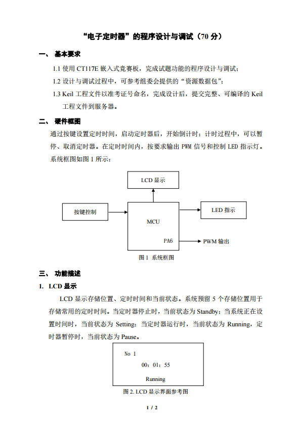
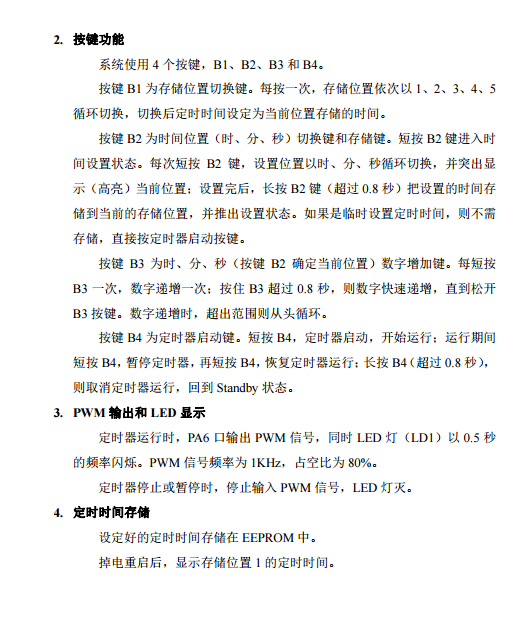
1, The 9th provincial Blue Bridge Competition


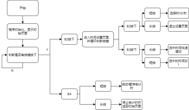
2, Program flow chart
 The program flow chart is drawn after the program is written, according to the logical relationship of the program I compiled. The logical relationship of this problem is not complex, and the idea is very clear.
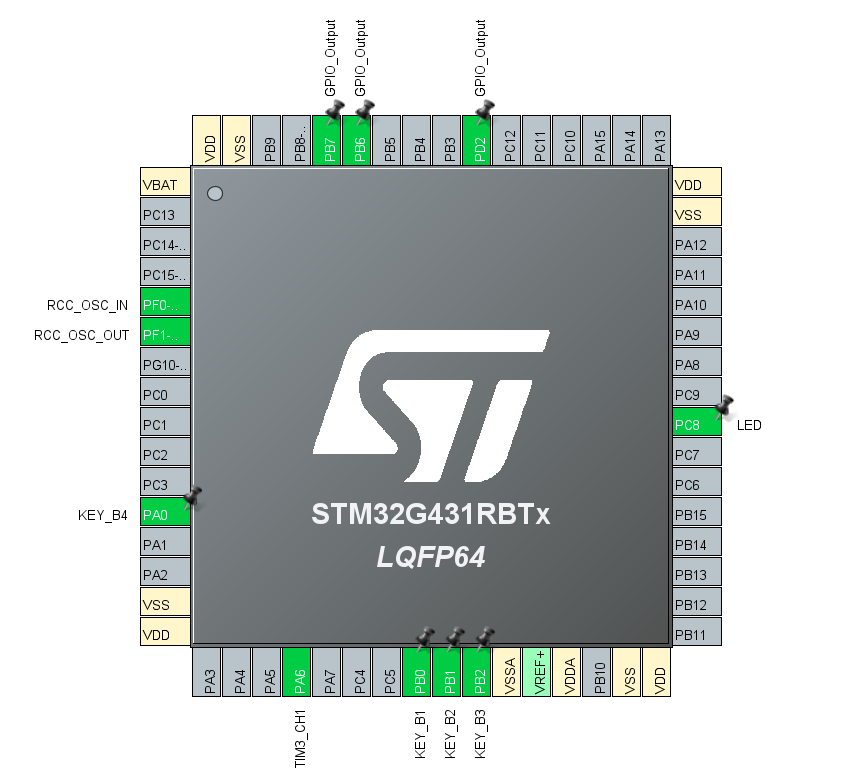
3, CUBEMX configuration
 The configurations here are all conventional configurations. Just match what you want according to the topic. Note here (also the error of my fan). Although there are I2C pins (PA6 and PA7) in the official EEPROM code, it needs to be configured in CUBEMX. The parameters can be configured by default. I read the code. I think it is because the pins in the routine are used directly without initialization. Therefore, if they are not configured in CUBEMX, they cannot be read and written to EEPROM.
4, Coding of each part
First, define the main function and variable:
/* Includes ------------------------------------------------------------------*/
#include "main.h"
#include "tim.h"
#include "gpio.h"
/* USER CODE BEGIN Includes */
#include "lcd.h"
#include "i2c.h"
#include "stdio.h"
#include "string.h"
/* USER CODE END Includes */
/* Private define ------------------------------------------------------------*/
/* USER CODE BEGIN PD */
struct Time{
    uint8_t hour;
    uint8_t min;
    uint8_t sec;
} TT_1;
/* USER CODE END PD */
int go_stop = 1; //Timing start / end flag bit
int time_cnt4 = 0; //Timer 4 count value
int long_pushB2 = 0;  //B2 key long press the flag bit
int long_pushB3 = 0;  //B3 key long press the flag bit
uint8_t str[20];
uint8_t str1[10];
uint8_t str2[20] = "      **          ";
uint8_t str3[20] = "         **       ";
uint8_t str4[20] = "            **    ";
unsigned char str5[10];
uint8_t re_loc = 1; //Storage location flag bits, 1 to 5
extern uint8_t time_cnt; //External variables, in xxxit c. Timer count value
extern uint8_t sec_08;  //External variables, in xxxit c. 0.8 second timing flag bit
/* USER CODE END PV */
/* Private function prototypes -----------------------------------------------*/
void SystemClock_Config(void);
/* USER CODE BEGIN PFP */
uint8_t x24c02_read(uint8_t address); //EEPROM read function
void x24c02_write(unsigned char address,unsigned char info);  //EEPROM write function
void loc_change(void);  //Change storage location
void time_setting(void);  //Set time
void time_go_stop(void);  //Start / end timer
void led_flash(void);  //led flashing
void PWM_gen(void);  //PWM wave generation function
void res_time(void);//Storage time
void read_time(void);//Read time
/* USER CODE END PFP */
/* Private user code ---------------------------------------------------------*/
int main(void)
{
  /* USER CODE BEGIN 1 */
    TT_1.hour = 0;
    TT_1.min = 0;
    TT_1.sec = 0;
  /* USER CODE END 1 */
  HAL_Init();
  /* USER CODE BEGIN Init */
    I2CInit();
    LCD_Init();
    LCD_Clear(White);
    LCD_SetBackColor(White);
    LCD_SetTextColor(Black);
  /* USER CODE END Init */
  /* Configure the system clock */
  SystemClock_Config();
  /* USER CODE BEGIN SysInit */
  /* USER CODE END SysInit */
  /* Initialize all configured peripherals */
  MX_GPIO_Init();
  MX_TIM2_Init();
  MX_TIM3_Init();
  MX_TIM4_Init();
  /* USER CODE BEGIN 2 */
  read_time();
  sprintf((char *)str,"      %02d:%02d:%02d",TT_1.hour,TT_1.min,TT_1.sec);
  LCD_DisplayStringLine(Line4,str);
  sprintf((char *)str1,"   No %d",re_loc);
  LCD_DisplayStringLine(Line1,str1);
  LCD_DisplayStringLine(Line7,"       Standby");
  /* USER CODE END 2 */
  /* USER CODE BEGIN WHILE */
  while (1)
  {
    /* USER CODE END WHILE */
    /* USER CODE BEGIN 3 */
      loc_change();
      time_setting();
      time_go_stop();
      //PWM_gen();
      HAL_Delay(5);
  }
  /* USER CODE END 3 */
}
Next, at the end of the paper, the functions of each function are written according to each requirement
1. Realization of storage location change function
This function is relatively basic. It is only a short press, which is very routine. However, it should be noted that the EEPROM must be read again every time the storage location is changed. The code is as follows:
void loc_change(void)
{
    if(HAL_GPIO_ReadPin(KEY_B1_GPIO_Port,KEY_B1_Pin) == 0)
    {
        HAL_Delay(100);
        if(HAL_GPIO_ReadPin(KEY_B1_GPIO_Port,KEY_B1_Pin) == 0)//Judge whether the key is pressed
        {
            re_loc++;
            if(re_loc > 5)//Greater than 5 becomes 1, cycle
            {
                re_loc = 1;
            }
            read_time(); //If you change, you have to read the time again
            sprintf((char *)str1,"   No %d",re_loc); //The following are LCD display functions
            LCD_DisplayStringLine(Line1,str1);
            sprintf((char *)str,"      %02d:%02d:%02d",TT_1.hour,TT_1.min,TT_1.sec);
            LCD_DisplayStringLine(Line4,str);
        }
    }
}
2. Compilation of time setting function
This one is the most complex, involving the long and short pressing of keys, nesting of keys, etc. the logical relationship is relatively complex. Here I explain my idea: first, after pressing B2, the program enters a dead cycle, scans it to judge whether there is a key press, makes different reactions according to different keys, and calculates the time of key press at the same time, If it is greater than 0.8 seconds, nine is considered as long press and make corresponding actions. The general idea is like this. Next, on the program, I have more ideas and program notes. I should be able to understand my programming ideas.
void time_setting(void)
{
    int i = 0;
    if(HAL_GPIO_ReadPin(KEY_B2_GPIO_Port,KEY_B2_Pin) == 0)
    {
        HAL_Delay(150);
        if(HAL_GPIO_ReadPin(KEY_B2_GPIO_Port,KEY_B2_Pin) == 0)//Judge whether B2 is pressed
        {
            LCD_DisplayStringLine(Line5,str4);
            LCD_DisplayStringLine(Line7,"       Setting");//Display Setting
            while(1) //Enter the dead cycle
            {
                if(HAL_GPIO_ReadPin(KEY_B2_GPIO_Port,KEY_B2_Pin) == 0)
                {
                    HAL_Delay(100);
                    if(HAL_GPIO_ReadPin(KEY_B2_GPIO_Port,KEY_B2_Pin) == 0)//Judge whether B2 is pressed
                    {
                        i++;   //This is the flag bit for setting hours, minutes and seconds, 0 --- seconds, 1 --- minutes, 2 --- hours
                        if(i > 2)
                        {
                            i = 0;
                        }
                        if( i == 0)
                        {
                            LCD_DisplayStringLine(Line5,str4);
                        }
                        if( i == 1)
                        {
                            LCD_DisplayStringLine(Line5,str3);
                        }
                        if( i == 2)
                        {
                            LCD_DisplayStringLine(Line5,str2);
                        }
                        while(HAL_GPIO_ReadPin(KEY_B2_GPIO_Port,KEY_B2_Pin) == 0)//If you keep pressing
                        {
                            HAL_TIM_Base_Start_IT(&htim2);//Turn on the timer
                            if(sec_08 == 1)//Judge whether the flag bit of 0.8 seconds is 1. If it is 1, it means that 0.8 seconds has arrived
                            {
                                long_pushB2 = 1;//Long press sign position 1
                                break;
                            }
                        }
                        HAL_TIM_Base_Stop_IT(&htim2);
                        time_cnt = 0;
                        sec_08 = 0;

                    }
                }
                if(HAL_GPIO_ReadPin(KEY_B3_GPIO_Port,KEY_B3_Pin) == 0)
                {
                    HAL_Delay(100);
                    if(HAL_GPIO_ReadPin(KEY_B3_GPIO_Port,KEY_B3_Pin) == 0)//Judge whether B3 is pressed
                    {
                        if(i == 0 )//The number of increases is determined according to the value of i
                        {
                            TT_1.sec++;
                        }
                        if(i == 1 )
                        {
                            TT_1.min++;
                        }
                        if(i == 2 )
                        {
                            TT_1.hour++;
                        }
                        sprintf((char *)str,"      %02d:%02d:%02d",TT_1.hour,TT_1.min,TT_1.sec);
                        LCD_DisplayStringLine(Line4,str);
                        while(HAL_GPIO_ReadPin(KEY_B3_GPIO_Port,KEY_B3_Pin) == 0)//If you keep pressing
                        {
                            HAL_TIM_Base_Start_IT(&htim2);//Turn on the timer
                            if(sec_08 == 1)//Judge whether the flag bit of 0.8 seconds is 1. If it is 1, it means that 0.8 seconds has arrived
                            {
                                long_pushB3 = 1;//Long press sign position 1
                                break;
                            }
                        }
                        HAL_TIM_Base_Stop_IT(&htim2);
                        time_cnt = 0;
                        sec_08 = 0;
                        while(long_pushB3 == 1 && HAL_GPIO_ReadPin(KEY_B3_GPIO_Port,KEY_B3_Pin) == 0)//Long press the flag bit to 1 and keep pressing it
                        {
                         if(i == 0 )//The fast-growing number is determined according to the value of i
                        {
                            TT_1.sec++;
                            HAL_Delay(95);
                            if(TT_1.sec == 60)
                            {
                                TT_1.sec = 0;
                                TT_1.min++;
                            }
                        }
                        if(i == 1 )
                        {
                            TT_1.min++;
                            HAL_Delay(95);
                            if(TT_1.min == 60)
                            {
                                TT_1.min = 0;
                                TT_1.hour++;
                            }
                        }
                        if(i == 2 )
                        {
                            TT_1.hour++;
                            HAL_Delay(95);
                            if(TT_1.hour == 24)
                            {
                                TT_1.hour = 0;
                            }
                        }
                        sprintf((char *)str,"      %02d:%02d:%02d",TT_1.hour,TT_1.min,TT_1.sec);//Update time
                        LCD_DisplayStringLine(Line4,str);
                    }
                    long_pushB3 = 0;
                    }
                }
                if(HAL_GPIO_ReadPin(KEY_B4_GPIO_Port,KEY_B4_Pin) == 0 || long_pushB2 == 1)
                {
                    HAL_Delay(60);
                    if(HAL_GPIO_ReadPin(KEY_B4_GPIO_Port,KEY_B4_Pin) == 0 || long_pushB2 == 1)//Judge whether B4 is pressed or whether B2 is pressed for a long time
                    {
                        if(long_pushB2 == 0)//B2 no long press
                        {
                            LCD_DisplayStringLine(Line5,"                  ");
                            LCD_DisplayStringLine(Line7,"       Running");
                            go_stop = 1;//Start timer
                            break;
                        }
                        if(long_pushB2 == 1)//B2 long press
                        {
                            LCD_DisplayStringLine(Line5,"                  ");
                            LCD_DisplayStringLine(Line7,"       Standby");
                            long_pushB2 = 0;
                            res_time();//Save time in EEPROM
                            HAL_Delay(200);
                            break;
                        }
                    }
                }

           }
      }
  }
}
3. Timer start / end function
The logical relationship of this block is relatively simple, that is, press the key to start the timer, then press the stop timer, and long press to return to the initial page. There are also key nesting and key long and short press. However, I have encountered a problem in this area, because I use timer interrupt for countdown, but my time is defined by structure. It is difficult to use extern for external call. After checking the data, it is found that using extern for structure is very troublesome (I am too lazy), so I use interrupt callback function:
void HAL_TIM_PeriodElapsedCallback(TIM_HandleTypeDef *htim)
It's hard to knock this with keil. I don't feel this when I use vscode and clion. I won't say more about timer interrupt. Go directly to the code:
void time_go_stop(void)
{
    if(HAL_GPIO_ReadPin(KEY_B4_GPIO_Port,KEY_B4_Pin) == 0)
        {
                    HAL_Delay(150);
                    if(HAL_GPIO_ReadPin(KEY_B4_GPIO_Port,KEY_B4_Pin) == 0)//Judge whether the key B4 is pressed
                    {
                        while(1)//Enter the dead cycle
                        {
                            if(HAL_GPIO_ReadPin(KEY_B4_GPIO_Port,KEY_B4_Pin) == 0)
                            {
                                HAL_Delay(50);
                                if(HAL_GPIO_ReadPin(KEY_B4_GPIO_Port,KEY_B4_Pin) == 0)//Judge whether key 4 is pressed
                                {
                                    go_stop = 1-go_stop;
                                    while(HAL_GPIO_ReadPin(KEY_B4_GPIO_Port,KEY_B4_Pin) == 0)//If you keep pressing
                                    {
                                        HAL_TIM_Base_Start_IT(&htim2);
                                        if(sec_08 == 1)//Judge whether the flag bit of 0.8 seconds is 1. If it is 1, it means that 0.8 seconds has arrived
                                        {
                                            long_pushB4 = 1;//Judge whether the flag bit of 0.8 seconds is 1. If it is 1, it means that 0.8 seconds has arrived
                                            break;
                                        }
                                    }
                                    HAL_TIM_Base_Stop_IT(&htim2);
                                    time_cnt = 0;
                                    sec_08 = 0;
                                }
                            }
                            if(long_pushB4 == 1)//Long press to exit and return to the initial page
                            {
                                long_pushB4 = 0;
                                LCD_DisplayStringLine(Line7,"       Standby");
                                sprintf((char *)str,"      %02d:%02d:%02d",TT_1.hour,TT_1.min,TT_1.sec);
                                LCD_DisplayStringLine(Line4,str);
                                HAL_Delay(150);
                                break;
                            }
                            if(go_stop == 1)//Timer start
                            {
                                LCD_DisplayStringLine(Line7,"       Running");
                                HAL_TIM_PWM_Start(&htim3,TIM_CHANNEL_1);//Start PWM
                                led_flash();//On LED flashing
                                HAL_TIM_Base_Start_IT(&htim4);//Start timer TIM4
                                if(TT_1.hour == 0 && TT_1.min==0 && TT_1.sec == 0)
                                {
                                    HAL_TIM_Base_Start_IT(&htim4);
                                    go_stop = 0;
                                }
                                sprintf((char *)str,"      %02d:%02d:%02d",TT_1.hour,TT_1.min,TT_1.sec);
                                LCD_DisplayStringLine(Line4,str);
                            }
                            if(go_stop == 0)//Timer end
                            {
                                LCD_DisplayStringLine(Line7,"       Pause  ");
                                HAL_TIM_Base_Stop_IT(&htim4);
                                time_cnt4 = 0;
                                HAL_TIM_PWM_Stop(&htim3,TIM_CHANNEL_1);
                                HAL_GPIO_WritePin(LED_GPIO_Port,LED_Pin,GPIO_PIN_SET);
                                HAL_GPIO_WritePin(GPIOD,GPIO_PIN_2,GPIO_PIN_SET);
                                HAL_GPIO_WritePin(GPIOD,GPIO_PIN_2,GPIO_PIN_RESET);
                            }
                        }
                    }
        }
}

void HAL_TIM_PeriodElapsedCallback(TIM_HandleTypeDef *htim)//Interrupt callback function
{

    if(htim -> Instance == htim4.Instance)//If TIM4 is interrupted
    {
        time_cnt4++;
        if(time_cnt4 == 100)//One second counts
        {
            TT_1.sec--;
            if(TT_1.sec == 255)//uint8 type 0-1 = = 255, complement operation
            {
                TT_1.sec = 59;
                TT_1.min--;
            }
            if(TT_1.min == 255)
            {
                TT_1.min = 59;
                TT_1.hour--;
            }
            time_cnt4 = 0;
        }
    }
}
So far, the main code of the project has been written, and there is no problem in the actual measurement. The problem is satisfactorily ended.
summary
- When using EEPROM, you need to configure the corresponding I2C pin in CUBEMX, because there is no initialization of IO port in the official routine.
- When continuously writing / reading EEPROM data, a delay of 10ms is required between two operations. It should be that I2C communication will respond. Without delay, it is impossible to write / read continuously.
- I'm not familiar with the external call of the structure, so I need to check more materials to learn.
Download of engineering documents of the 9th provincial competition: Download link