Use of PIC32 series timer TMR-16 bit external synchronous timer
2. Scheme description of 16 bit synchronous external timer
3. 16 bit synchronous external timer Harmony3 configuration
4. Engineering configuration analysis
6. Description of 16 bit synchronous external clock counter
7. 16 bit synchronous external clock counter initialization steps
1. PIC32 reference resources
PIC32 series reference manual Chinese version} link address: PIC32 series Reference Manual Chapter 14 timer
2. Scheme description of 16 bit synchronous external timer
Step 1: TMR3 generates a fixed frequency pulse signal;
Step 2: TMR2 is set as external clock input;
Step 3: present the pulse signal generated by TMR3 to the pin level change, and connect the pin to the external clock input pin of TMR2;
Step 4: in TMR2 interrupt, set the LED level to flip for a fixed time;
3. 16 bit synchronous external timer Harmony3 configuration
1. Timer 3 is configured with frequency division coefficient of 2, internal clock source, timing time of 0.5ms and frequency of 1Khz;

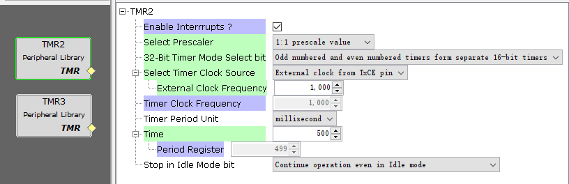
2. Timer 2 is configured with a frequency division coefficient of 1. The external clock source is selected as the clock source. The clock frequency is filled in 1000Hz and the timing time is filled in 500ms;
3. After the component configuration is completed, click the Generate Code button on the left to generate the code;
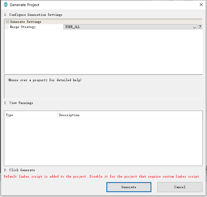
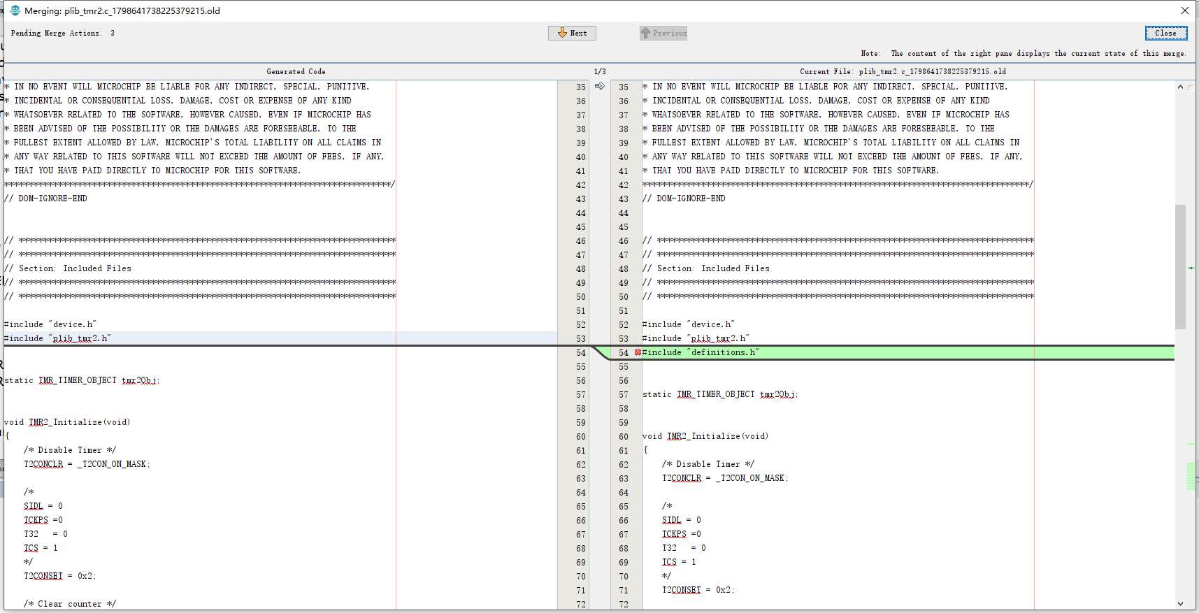
4. The generated code is different from the original code and needs to be confirmed;
5. Operations required after code generation;
1. Add the start of timer TMR3 and TMR2;
2. Add pin level reversal to TMR3 interrupt service function to generate pulse signal for providing external clock input;
3. Add LED level flip in TMR2 interrupt service function;
4. TMR2 clock external input pin connected with TMR3 output pin in external interface;
6. Compile and run to burn the code into the development board;
Click the compile button to prompt BUILD SUCCESSFUL. Click burn to prompt Programming/Verify complete. The LED on the development board flashes.
4. Engineering configuration analysis
1. TMR3 timer engineering configuration

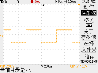
Timer TMR3 is mainly used to generate external clock. We modify the frequency division coefficient to 2 and select the internal clock as the clock source. Then the clock frequency of the timer is 40MhHz. We make the timing time 0.5ms, that is, the cycle is 1kHz.
We flip the level of an IO port in the interrupt to generate the external clock required by TMR2. The waveform capture is as follows, with a time of 0.5ms and a frequency of 1kHz;
2. TMR2 engineering configuration

Timer TMR2 mainly counts based on external frequency. We set the frequency division coefficient to 1, select the external clock as the clock source, fill in the external clock frequency of 1000Hz, and set the timing time to 500ms.
That is, 500 counts at a frequency of 1 ms is 500 ms. At this time, set the LED light turnover in the interrupt service function of TMR2, and the turnover time is 500ms.
5. Specific code analysis
Timer TMR3
//Timer TMR3 initialization
void TMR3_Initialize(void)
{
    /* Disable Timer */
    T3CONCLR = _T3CON_ON_MASK; //Disable the timer and clear the ON control bit

    /*
    SIDL = 0 //Idle mode stop bit
    TCKPS =1 //Prescaler setting
    T32   = 0 //32 timer
    TCS = 0 //Clock source selection, internal clock source or external clock source
    */
    T3CONSET = 0x10;  //TxCON 16 bit control register associated with timer

    /* Clear counter */
    TMR3 = 0x0; //TMRx 16 bit timer counter register

    /*Set period */
    PR3 = 19999U; //PRx 16 bit cycle register associated with timer

    /* Enable TMR Interrupt */
    IEC0SET = _IEC0_T3IE_MASK; //TxIE interrupt allows the control bit to be in the IEC0 interrupt register
}

//Start timer TMR3
void TMR3_Start(void)
{
    T3CONSET = _T3CON_ON_MASK; //TxIF interrupt flag status bit is in IFS0 interrupt register;
}

//Turn off timer TMR3
void TMR3_Stop (void)
{
    T3CONCLR = _T3CON_ON_MASK; //TxIF interrupt flag status bit is in IFS0 interrupt register;
}

//Set cycle register
void TMR3_PeriodSet(uint16_t period)
{
    PR3  = period; //PRx 16 bit cycle register associated with timer
}

//Get cycle register
uint16_t TMR3_PeriodGet(void)
{
    return (uint16_t)PR3; //PRx 16 bit cycle register associated with timer
}

//Get count value
uint16_t TMR3_CounterGet(void)
{
    return (uint16_t)(TMR3); //TMRx 16 bit timer counter register
}

//Get timer frequency
uint32_t TMR3_FrequencyGet(void)
{
    return (40000000); //Returns the clock frequency of the timer
}

//Timer 3 interrupt service function
void TIMER_3_InterruptHandler (void)
{
    uint32_t status  = 0U;
    status = IFS0bits.T3IF;
    IFS0CLR = _IFS0_T3IF_MASK;

    /*Interrupt handling content can be added here*/
    GPIO_RB1_Toggle();

    if((tmr3Obj.callback_fn != NULL))
    {
        tmr3Obj.callback_fn(status, tmr3Obj.context);
    }
}

//Interrupt enable
void TMR3_InterruptEnable(void)
{
    IEC0SET = _IEC0_T3IE_MASK; //TxIE interrupt allows the control bit to be in the IEC0 interrupt register
}

//Prohibit interrupt
void TMR3_InterruptDisable(void)
{
    IEC0CLR = _IEC0_T3IE_MASK; //TxIE interrupt allows the control bit to be in the IEC0 interrupt register
}

//
void TMR3_CallbackRegister(TMR_CALLBACK callback_fn, uintptr_t context)
{
    /* Save callback_fn and context in local memory */
    tmr3Obj.callback_fn = callback_fn;
    tmr3Obj.context = context;
}

//Interrupt service function, in interrupts In C, call TIMER_. 3_ InterruptHandler
void __ISR(_TIMER_3_VECTOR, ipl1SOFT) TIMER_3_Handler (void)
{
    TIMER_3_InterruptHandler();
}
Timer TMR2
//Timer TMR2 initialization
void TMR2_Initialize(void)
{
    /* Disable Timer */
    T2CONCLR = _T2CON_ON_MASK; //Disable the timer and clear the ON control bit

    /*
    SIDL = 0 //Idle mode stop bit
    TCKPS =0 //Prescaler setting
    T32   = 0 //32 timer
    TCS = 1 //Clock source selection, internal clock source or external clock source
    */
    T2CONSET = 0x2;  //TxCON 16 bit control register associated with timer

    /* Clear counter */
    TMR2 = 0x0; //TMRx 16 bit timer counter register

    /*Set period */
    PR2 = 499U; //PRx 16 bit cycle register associated with timer

    /* Enable TMR Interrupt */
    IEC0SET = _IEC0_T2IE_MASK; //TxIE interrupt allows the control bit to be in the IEC0 interrupt register
}

//Start timer TMR2
void TMR2_Start(void)
{
    T2CONSET = _T2CON_ON_MASK; //TxIF interrupt flag status bit is in IFS0 interrupt register;
}

//off timer
void TMR2_Stop (void)
{
    T2CONCLR = _T2CON_ON_MASK; //TxIF interrupt flag status bit is in IFS0 interrupt register;
}

//Set cycle register
void TMR2_PeriodSet(uint16_t period)
{
    PR2  = period; //PRx 16 bit cycle register associated with timer
}

//Get cycle register
uint16_t TMR2_PeriodGet(void)
{
    return (uint16_t)PR2;  //PRx 16 bit cycle register associated with timer
}

//Get count value
uint16_t TMR2_CounterGet(void)
{
    return (uint16_t)(TMR2); //TMRx 16 bit timer counter register
}

//Get timer frequency
uint32_t TMR2_FrequencyGet(void)
{
    return (1000); //Returns the clock frequency of the timer
}

//Timer interrupt service function
void TIMER_2_InterruptHandler (void)
{
    uint32_t status  = 0U;
    status = IFS0bits.T2IF;
    IFS0CLR = _IFS0_T2IF_MASK;

/*Interrupt handling content can be added here*/
GPIO_RB0_Toggle();

    if((tmr2Obj.callback_fn != NULL))
    {
        tmr2Obj.callback_fn(status, tmr2Obj.context);
    }
}

//Interrupt enable
void TMR2_InterruptEnable(void)
{
    IEC0SET = _IEC0_T2IE_MASK; //TxIE interrupt allows the control bit to be in the IEC0 interrupt register
}

//Prohibit interrupt
void TMR2_InterruptDisable(void)
{
    IEC0CLR = _IEC0_T2IE_MASK; //TxIE interrupt allows the control bit to be in the IEC0 interrupt register
}

//
void TMR2_CallbackRegister(TMR_CALLBACK callback_fn, uintptr_t context)
{
    /* Save callback_fn and context in local memory */
    tmr2Obj.callback_fn = callback_fn;
    tmr2Obj.context = context;
}

//Interrupt service function, in interrupts In C, call TIMER_. 2_ InterruptHandler
void __ISR(_TIMER_2_VECTOR, ipl1SOFT) TIMER_2_Handler (void)
{
    TIMER_2_InterruptHandler();
}
Interrupt priority configuration
//Interrupt priority setting, setting TMR2 and TMR3 priorities
void EVIC_Initialize( void )
{
    INTCONSET = _INTCON_MVEC_MASK;
    /* Set up priority and subpriority of enabled interrupts */
    IPC2SET = 0x4 | 0x0;  /* TIMER_2:  Priority 1 / Subpriority 0 */
    IPC3SET = 0x4 | 0x0;  /* TIMER_3:  Priority 1 / Subpriority 0 */
}
6. Description of 16 bit synchronous external clock counter
Synchronous external clock counter operation provides the following functions:
• count periodic or aperiodic pulses
• use the external clock as the time base of the timer
Both class A and class B timers can operate in synchronous external clock counter mode. In this mode, the input clock source of the timer is the external clock applied to the TxCK pin. It is selected by setting the clock source control bit TCS to 1 (txcon < 1 > = 1). Class B timer will automatically provide external clock source synchronization; However, the class a timer does not and requires the external clock synchronization bit TSYNC (t1con < 2 >) to be set to 1 (= 1).
Class A or B timers that rely on synchronous external clock sources do not work in Sleep mode because the synchronization circuit is disabled in Sleep mode.
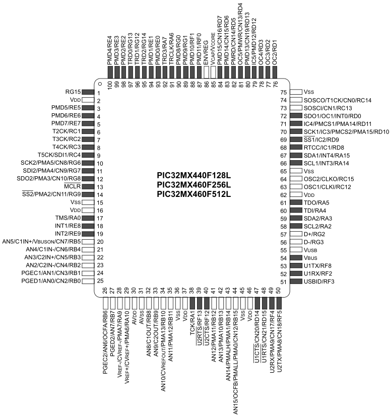
TCLK pins are RC1, RC2, RC3, RC4 and RC14 respectively, which should be noted.
7. 16 bit synchronous external clock counter initialization steps
1. Clear the ON control bit (txcon < 15 > = 0) to disable the timer.
2. Set TCS control position 1 (txcon < 1 > = 1) to select external clock source.
3. If class A timer is used, turn TSYNC control position 1 (t1con < 2 > = 1) to enable clock synchronization.
4. Select the desired timer input clock prescaler ratio.
5. Load / reset timer register TMRx.
6. If the service life matches:
a) load the required 16 bit matching value into the cycle register PRx.
7. If an interrupt is used:
a) clear the TxIF interrupt flag bit in the IFSx register.
b) configure interrupt priority and sub priority in IPCx register.
c) set TxIE interrupt allowable position 1 in IECx register.
8. Turn ON to control position 1 (txcon < 15 > = 1) to enable the timer.
8. Experimental verification
Click the compile button to prompt BUILD SUCCESSFUL. Click burn to prompt Programming/Verify complete. The LED on the development board flashes.
Time: August 2, 2021