4.9 (HC-SR04) ultrasonic ranging module
4.9.1 physical drawing of ultrasonic module
There is no ultrasonic ranging module on the experimental board, which is used in the form of external module.
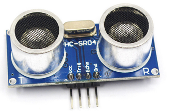
Figure 4-9-1
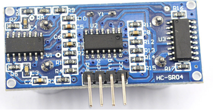
Figure 4-9-2
Function introduction of GPIO port of ultrasonic module:
(1) VCC supplies 5V power
(2) . GND is the ground wire
(3) . TRIG trigger control signal input
(4) ECHO echo signal output
4.9.2 introduction to function and working principle of ultrasonic module
HC-SR04 ultrasonic ranging module can provide 2cm-400cm non-contact distance sensing function, and the ranging accuracy can be as high as 3mm; The module includes ultrasonic transmitter, receiver and control circuit.
Basic working principle:
(1) . the single chip microcomputer controls the TRIG port of the ultrasonic to give at least 10us high-level signal to trigger ranging;
(2) The module will automatically send 8 40khz square waves and automatically detect whether there is signal return;
(3) When a signal returns, the module will output a high level through the ECHO port. The duration of the high level is the time from the transmission to the return of the ultrasonic. Formula: uS/58 = cm Or uS/148 = inch or distance = high level time * sound speed (340M/S)
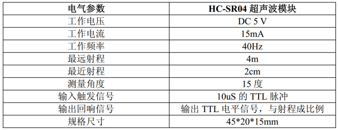
Figure 4-9-3 module electrical parameters
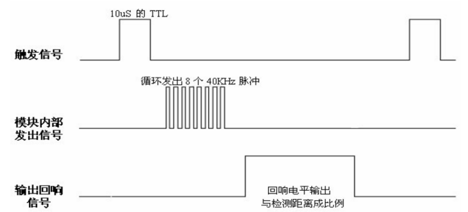
Fig. 4-9-4 sequence diagram
The above sequence diagram shows that the single chip microcomputer only needs to provide a pulse trigger signal of more than 10uS. The module will send 8 40kHz cycle levels and detect the echo. Once the module detects the echo signal, it will output the echo signal. The pulse width of the echo signal is directly proportional to the measured distance.
Thus, the distance can be calculated by the time interval from the transmitted signal to the received echo signal.
Formula: uS/58 = cm or uS/148 = inch; Or Distance = high level time * sound speed (340M/S) / 2;
It is recommended that the measurement period be more than 60ms to prevent the influence of the transmitted signal on the echo signal.
4.9.3 example code of ultrasonic ranging
There is no ultrasonic module on the currently used experimental board. At present, it is connected with the experimental board in the form of external module.
The model of ultrasonic module is HC-SR04.
Because the interrupt of the current 51 single chip microcomputer (STC90C51) cannot be configured to be triggered by the rising edge, the main program uses the way of blocking judgment to wait for the end of ranging, uses timer 0 to record the elapsed time, timer 0 turns on the overflow interrupt, and uses variables to record the times of interrupt overflow in the interrupt. At the end of ranging, calculate the measured distance through the overflow times of the timer and the value of the current timer to the recorded time, and finally print the measured distance to the computer terminal through the serial port.
(the maximum distance measured by the currently used ranging module is 4m, and the 16 bit timer is enough to count, so it is not necessary to start the timer overflow interrupt. The idea of the following program design is more general. If the distance measured by other ranging modules is farther, it can also be used.)
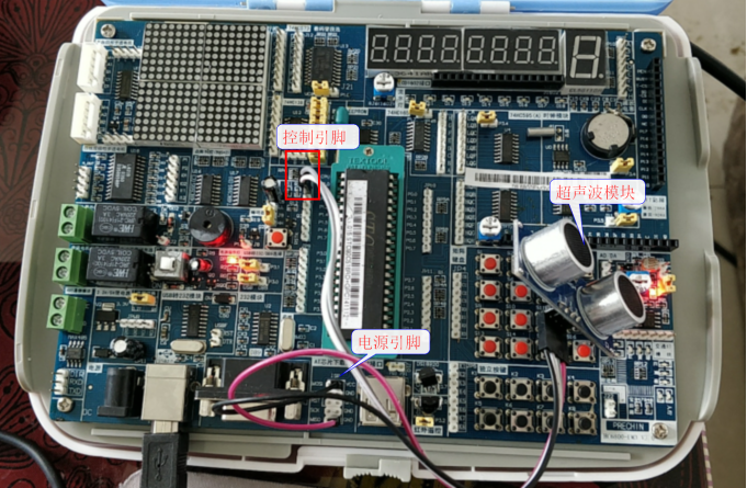
Figure 4-9-5 physical drawing
(description of hardware platform: CPU is STC90C516RD, crystal oscillator frequency is 12MHZ, working in 12T mode, and one machine cycle is 1us time)
Example code:
#include <reg51.h>
sbit ECHO=P1^0;  //Ultrasonic echo signal output pin
sbit TRIG=P1^1;  //Pin triggering ultrasonic ranging
u32 timt0_cnt=0; //Record the number of times timer 0 overflowed
u16 time_val=0;
float distance=0.0; //Save measured distance
void Timer0_16bit_Init(u16 us);
void DelayMs(u32 ms);
void delay20us(void);
int main()
{
    ECHO=0;
    TRIG=0;
    UART_Init(); //The baud rate of initialization serial port is 4800
    while(1)
    {
        TRIG=1;//Trigger ranging
        delay20us(); //Delay 20us
        TRIG=0;          //Stop triggering
        while(ECHO==0){} //Wait for the echo signal to return
        Timer0_16bit_Init(65535); //Initialize timer 0 and start counting
        while(ECHO==1){} //Wait for the echo signal to end
        TR0=0;           //Turn off timer 0
        time_val=(TH0<<8|TL0)+timt0_cnt*65535; //computing time
        distance=time_val/58.0; //Get the distance. The unit is centimeter
        printf("distance=%f CM\r\n",distance);
        timt0_cnt=0; //Clear overflow times
        DelayMs(1000); //Delay 1 second
    }
}

u16 T0_Update_data;//Initial value of timer 0
void Timer0_16bit_Init(u16 us)
{
    //At present, the actual frequency of the crystal oscillator on the experimental board is:   12MHZ
    u16 val=us/(12/12); //Get the count time, as long as the integer part
    T0_Update_data=65535-val; //Get the reload value
    TMOD&=0xF0;     //Clear configuration
    TMOD|=0x01;     //Configure timer 0 to operate in 16 bit timer mode
    TH0=T0_Update_data>>8; //Timer 0 high reassembly value
    TL0=T0_Update_data;    //Timer 0 low reassembly value
    TR0=1;          //Start timer 0
}

extern timt0_cnt; //Record the overflow times of timer 0
//Reload value update function for timer 0
void Timer0_Update(void)
{
    TH0=T0_Update_data>>8; //Timer 0 high reassembly value
    TL0=T0_Update_data;    //Timer 0 low reassembly value
    timt0_cnt++;           //Record the overflow times of timer 0
}

void DelayMs(u32 ms)
{
    u32 i;
    u8 a,b;
    for(i=0;i<ms;i++)
    {
    for(b=199;b>0;b--)
         for(a=1;a>0;a--);
    }
}
void delay20us(void)   //error   0us
{
    unsigned char a,b;
    for(b=1;b>0;b--)
        for(a=7;a>0;a--);
} 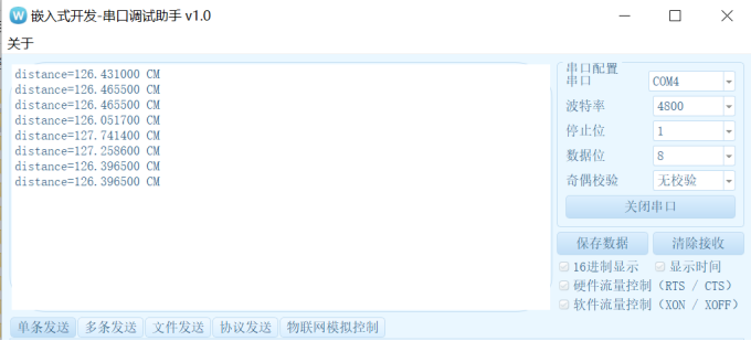
Figure 4-9-6 measured distance