Preface:
Finite state machine design technology is an important part of using data system design, and it is also an important way to realize high efficiency, high reliability and speed control logic system. In a broad sense, as long as the circuit of trigger is involved, the size of circuit without path can be reduced to state machine.
1. Description:
In the description part, the TYPE statement is used to define a new data TYPE, which is an enumeration TYPE. Its elements are usually defined by the state of the state machine. The state variables (such as the secondary state and the present state) should be defined as signals to facilitate the transmission of information. The data TYPE of the state machine is defined as the newly defined data TYPE with the given state elements. The description part is generally placed between arcitetecture and BEGIN, as follows:
ARCHITECTURE ....IS
    TYPE FSM_ST IS(S0,S1,S2,S3);
    SIGNAL current_state,next_state :FSM_ST;
BEGIN
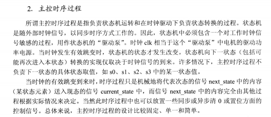
2. Master timing process:
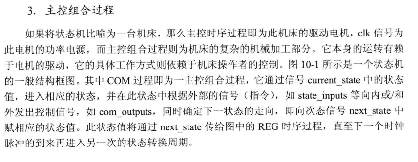
3. Main control combination process:
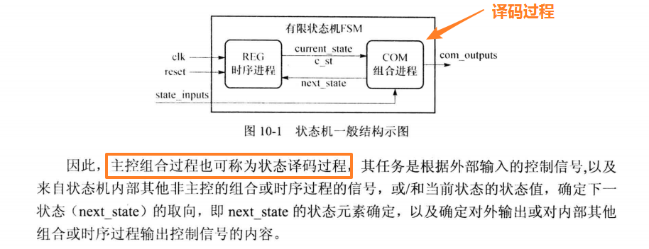
4. Auxiliary process:

Example: the following example is composed of two master processes, including master sequential process and master composite process (Note: C ﹣ st represents current ﹣ state):
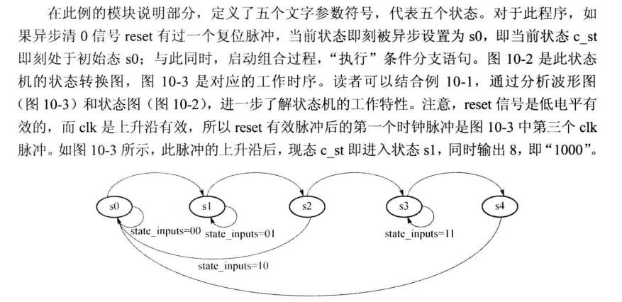
The structure diagram is as follows:

The procedure is as follows:
library ieee;
use ieee.std_logic_1164.all;
entity FSM_EXP is
port( clk,reset   :in std_logic;   --Working clock and reset signal of state machine
	  state_input :in std_logic_vector(0 to 1); --State machine control signal from outside
	  comb_outputs:out integer range 0 to 15);  --Control signals sent by state machine
end FSM_EXP;

architecture BHV of FSM_EXP is
	TYPE FSM_ST is (s0,s1,s2,s3,s4);  --Data type definition, defined as status symbol
	signal c_st,next_state :FSM_ST;   --Define the present state and the secondary state as the new data type as FSM_ST
begin
	REG:process(reset,clk)         begin --Master timing process
		if reset='0' then c_st<=s0;    --Reset signal detected, return to initial state after reset s0
		elsif clk='1' and clk'event then c_st<=next_state;
		end if;
	end process REG;

	COM:process(c_st,state_input)  begin
	case c_st is
		when s0=> comb_outputs<=5;   --get into the state s0 After output 5
			if state_input="00" then next_state<=s0; -
			else next_state<=s1;
			end if;
		when s1=> comb_outputs<=8;  --get into the state s1,Output 8
			if state_input="01" then next_state<=s1;
			else next_state<=s2;
			end if;
		when s2=> comb_outputs<=12;  --get into the state s2 Output 12
			if state_input="10" then next_state<=s0;  --Note that staying in state 3 will return to state 0
			else next_state<=s3;
			end if;
		when s3=> comb_outputs<=14;
			if state_input="11"  then next_state<=s3;
			else next_state<=s4;
			end if;
		when s4=> comb_outputs<=9;next_state<=s0;  --When it reaches state 4, it will automatically return to state 0
		when others => next_state<=s0;
	end case;
    end process COM;
end BHV;
Simulation test:
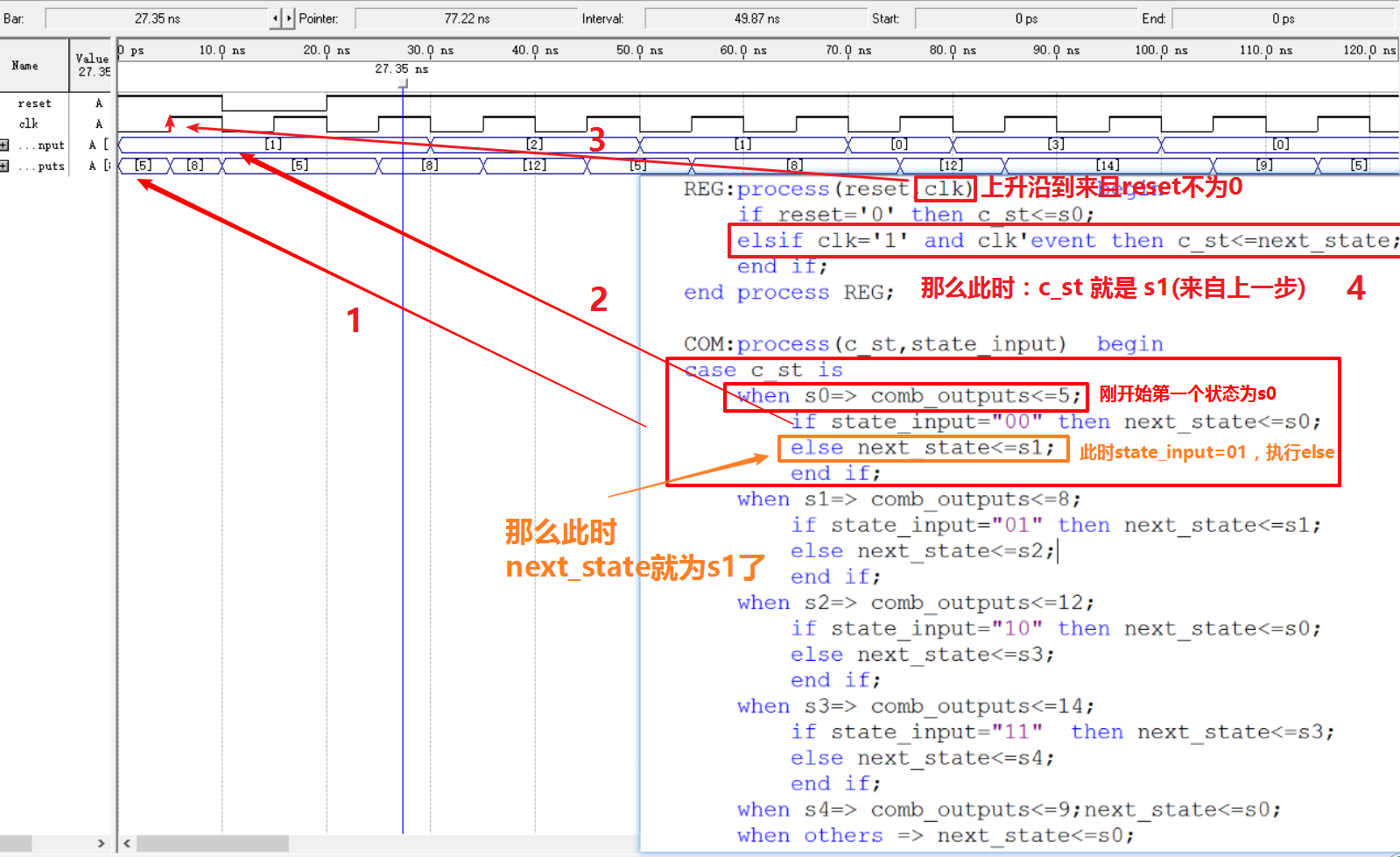
Next, go to the next step:
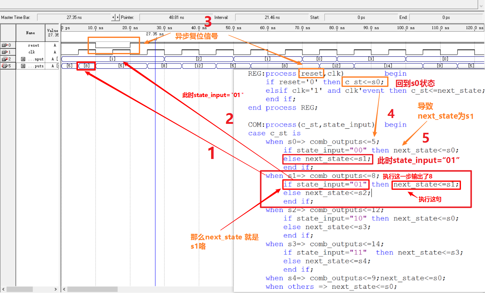
Next:
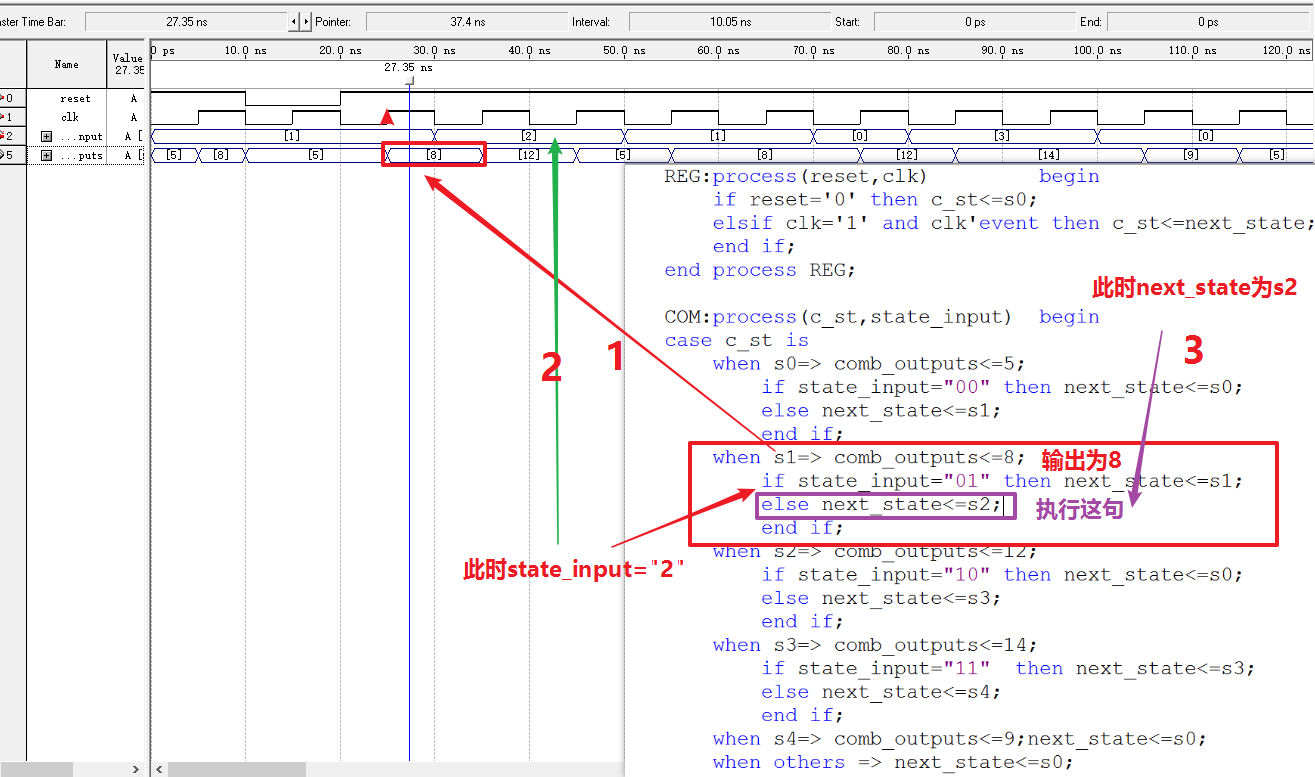
Next:
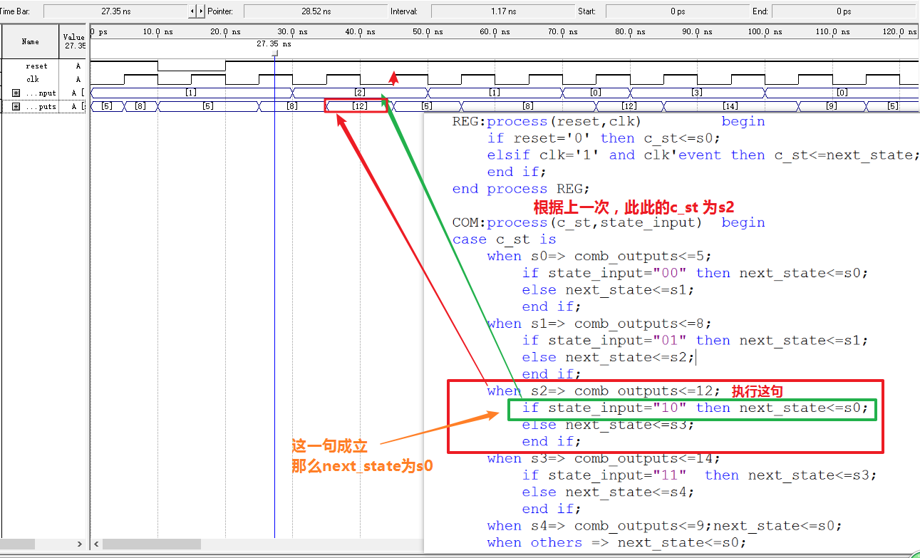
According to the above program, the next rising edge will update the value of next state to that of C st, that is, C st is s0, and the output value is 5;
Be careful:
