Catalog
- 1, Advertising water lamp experiment
- 1. Experimental equipment
- 2. Experimental wiring
- 3. Experiment principle
- 4. Program code
- 5. Experimental results
- 2, Traffic light design experiment
- 1. Experimental equipment
- 2. Experimental wiring
- 3. Experiment principle
- 4. Program code
- 5. Experimental results
- Three. Conclusion
This section is a preliminary attempt to use LED lights. Refer to other tutorials to do the following experiments.
1, Advertising water lamp experiment
1. Experimental equipment
- LED lights: 6, color optional.
- 220 Ω \ Omega Ω: 6.
- One breadboard and several jumpers.
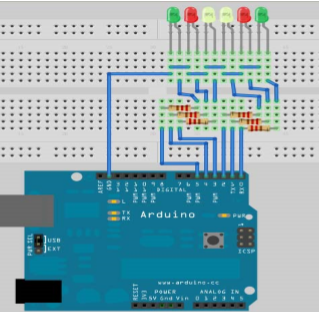
2. Experimental wiring
Connect 6 LED s to pins 1 ~ 6 in sequence, as shown below:
3. Experiment principle
Through the constant brightness change of LED lamp, the effect of running water lamp is realized. In the experiment, we control the order and time of the LED lights to achieve different effects.
- Style? 1(): LED lights up 6 LED lights in turn at an interval of 200ms from the light on the left. Then, six LED lights will be turned off at an interval of 200ms from the rightmost LED lights.
- Flash (): all 6 LED lights are on, with a delay of 200ms, and then all 6 lights are off. Two cycles create a flickering effect.
- Style 2 (): first, let the middle two lights on, then the other two lights next to them, and finally the two LED lights on both sides; then the lights on both sides go out, then the lights next to them go out, and finally the middle two lights go out.
- Style? 3 (): let the lights on both sides be on for 400ms, and then turn off; then let the two LED lights next to them be on for 400ms, and then turn off; finally, the middle two lights are on for 400ms, and then turn off
4. Program code
//Set control LED pin
int Led1=1;
int Led2=2;
int Led3=3;
int Led4=4;
int Led5=5;
int Led6=6;

void style_1(void)
{
  unsigned char j;
  for(j=1;j<=6;j++)
  {
    digitalWrite(j,HIGH);
    delay(200);
   }
   for(j=6;j>=1;j--)
   {
    digitalWrite(j,LOW);
    delay(200);
   }
}

void flash(void)
{
  unsigned char j,k;
  for(k=0;k<=1;k++)
  {
    for(j=1;j<=6;j++)
      digitalWrite(j,HIGH);
    delay(200);
    for(j=1;j<=6;j++)
      digitalWrite(j,LOW);
    delay(200);
  }
}

void style_2(void)
{
  unsigned char j,k;
  k=1;
  for(j=3;j>=1;j--)
  {
    digitalWrite(j,HIGH);
    digitalWrite(j+k,LOW);
    delay(400);
    k+=2;
  }
  k=5;
  for(j=1;j<=3;j++)
  {
    digitalWrite(j,LOW);
    digitalWrite(j+k,LOW);
    delay(400);
    k-=2;
  }
}

void style_3(void)
{
  unsigned char j,k;
  k=5;
  for(j=1;j<=3;j++)
  {
    digitalWrite(j,HIGH);
    digitalWrite(j+k,HIGH);
    delay(400);
    digitalWrite(j,LOW);
    digitalWrite(j+k,LOW);
    k-=2;
  }
  k=3;
  for(j=2;j>=1;j--)
  {
    digitalWrite(j,HIGH);
    digitalWrite(j+k,HIGH);
    delay(400);
    digitalWrite(j,LOW);
    digitalWrite(j+k,LOW);
    k+=2;
  }
}


void setup() {
  unsigned char i;
  for(i=1;i<=6;i++)
    pinMode(i,OUTPUT);//Set pin i as output mode
}

void loop() {
  style_1();
  flash();
  style_2();
  flash();
  style_3();
  flash();

}
5. Experimental results
Video of experimental results (60 frames were partially captured):
2, Traffic light design experiment
1. Experimental equipment
- Red, green and yellow LED lights: 3
- 220 Ω \ Omega Ω: 3
- Some bread board jumpers
- A breadboard
2. Experimental wiring
Three LED lights are connected to pins 4, 7 and 10 in turn, and the negative is connected to GND pin of Arduino board, as shown below: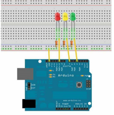
3. Experiment principle
In this experiment, we mainly control the time interval between the red, green and yellow lights to achieve the simulation effect of traffic lights in turn. In fact, the time interval between the red, green and yellow lights is generally determined, which is the purpose of our experiment.
4. Program code
//Define digital pins 4, 7, 10
int ledred=10;
int ledyellow=7;
int ledgreen=4;

void setup() {
//Set up digital interface
  pinMode(ledred,OUTPUT);
  pinMode(ledyellow,OUTPUT);
  pinMode(ledgreen,OUTPUT);
}

void loop() {
  digitalWrite(ledred,HIGH);
  delay(1000);
  digitalWrite(ledred,LOW);
  digitalWrite(ledyellow,HIGH);
  delay(500);
  digitalWrite(ledyellow,LOW);
  digitalWrite(ledgreen,HIGH);
  delay(1000);
  digitalWrite(ledgreen,LOW);

}
5. Experimental results
The captured video is converted into GIF motion picture as follows:
Three. Conclusion
Practice is in the real knowledge. Through frequent practice, we will be more familiar with the knowledge we learn, and we will find some problems from it, so as to increase our practical ability.

