Original text: https://circuitdigest.com/microcontroller-projects/arduino-metal-detector-circuit-code
Arduino metal detector
Pass by** Saddam **Revised on January 6, 2018
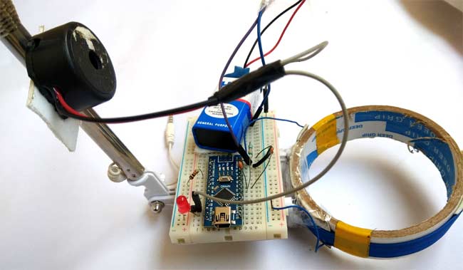
Metal detector is a kind of safety device, which can be used to detect potentially harmful metals in airports, shopping malls, cinemas and other places. We've made a lot of films before Simple without microcontroller Now we are building metal detectors using Arduino. In this project, we will use coils and capacitors to detect metal. Here, we used Arduino Nano to build this metal detector project. This is a very interesting project for all electronics enthusiasts. Whether the detector detects any metal nearby, the buzzer will beep very quickly.
Required components:
The following are the components needed to build a simple DIY metal detector using Arduino. All of these components should be readily available in your local hardware store.
- Arduino (any)
- Coiled material
- 10nF capacitor
- Buzzer
- 1k resistance
- 330 ohm resistance
- guide
- 1N4148 diode
- Bread board or PCB
- Connecting jumper
- 9v battery
How does the metal detector work?
Whenever a current flows through the coil, a magnetic field is generated around the coil. Changes in the magnetic field produce an electric field. Now, according to Faraday's law, due to the electric field, a voltage will be generated at both ends of the coil, which is opposite to the change of the magnetic field. This is the way the coil generates inductance, which means that the generated voltage is opposite to the increase of current. The unit of inductance is Henry, and the formula for measuring inductance is:
L = (μο * N2 * A) / l
Where,
L- Inductance in Henries
μο- Permeability, its 4π*10-7 for Air
N- Number of turns
A- Inner Core Area (πr2) in m2
l- Length of the Coil in meters
When any metal approaches the coil, the coil changes its inductance. This change in inductance depends on the type of metal. It decreases for non-magnetic metals and increases for ferromagnetic materials such as iron.
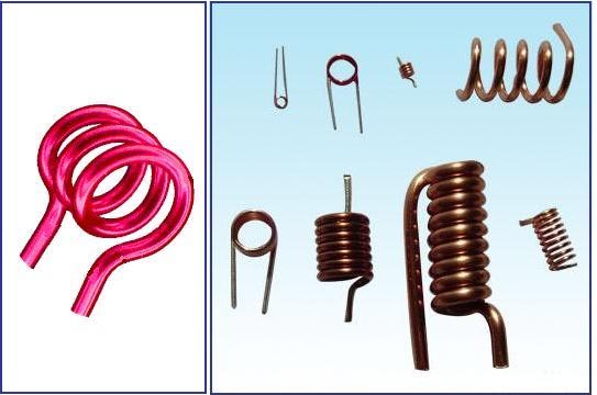
Depending on the magnetic core of the coil, the inductance value will change sharply. In the figure below, you can see hollow inductors, in which there will be no solid core. They are basically coils left in the air. The flowing medium of the magnetic field generated by the inductor is empty or air. The inductance of these inductors is very small.
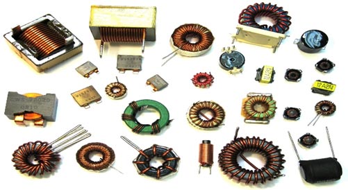
These inductors can be used when few micro Henry values are required. Not suitable for values greater than a few milliohms. In the figure below, you can see the inductor with ferrite core. These ferrite core inductors have very large inductance values.
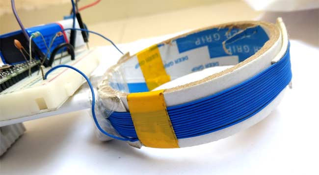
Remember that the coil wound here is a hollow coil, so when a metal sheet is placed near the coil, the metal sheet will be used as the magnetic core of the hollow inductor. By using this metal as the core, the inductance of the coil changes or increases significantly. Compared with the case without metal sheet, the total reactance or impedance of LC circuit changes considerably due to the sudden increase of coil inductance.
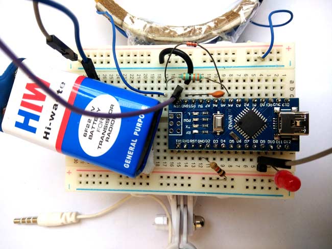
Therefore, in this Arduino Metal Detector project, we must find the inductance of the coil to detect the metal. For this purpose, we use the LR circuit (resistor inductor circuit) already mentioned. In this circuit, we use a coil with about 20 turns or a winding with a diameter of 10cm. We used an empty roll of tape and wound the wire around it to make a coil.
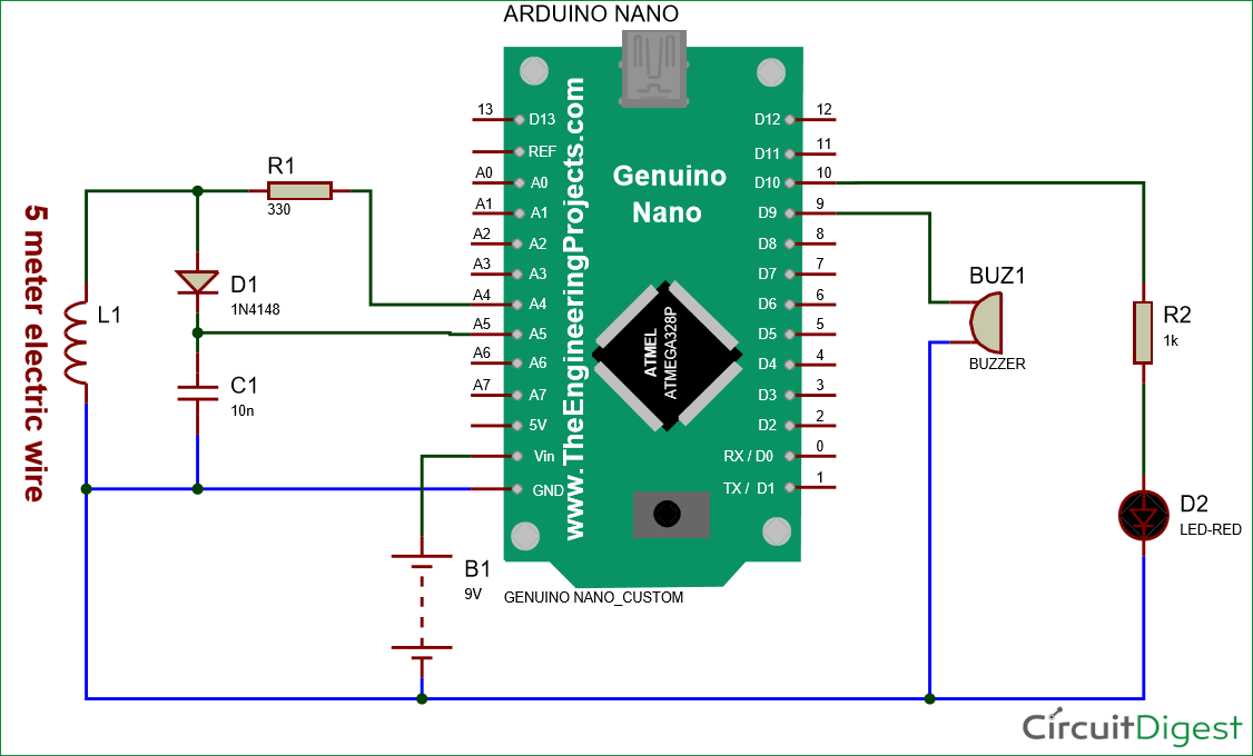
Circuit diagram:
We have used Arduino Nano to control the whole Metal Detector project. LED and buzzer are used as metal detection indicators. Coils and capacitors are used to detect metals. The signal diode is also used to reduce the voltage. There is also a resistor to limit the current to the Arduino pin.
Job description:
This Arduino Metal Detector is a bit tricky. Here, we supply the block wave or pulse generated by Arduino to LR high pass filter. Therefore, in each transition phase, the coil will produce short spikes. The pulse length of the generated spike is directly proportional to the inductance of the coil. Therefore, with the help of these spikes, we can measure the inductance of the coil. However, it is difficult to accurately measure the inductance of those spikes, because the duration of these spikes is very short (about 0.5 microseconds), and Arduino is difficult to measure.
Therefore, instead, we use a capacitor charged by a rising pulse or spike. Moreover, it only needs a few pulses to charge the capacitor to the extent that the Arduino analog pin A5 can read its voltage. Arduino then reads the voltage of the capacitor using an ADC. After reading the voltage, the capacitor discharges rapidly by taking the capPin pin pin as the output and setting it to low level. The whole process takes about 200 microseconds. In order to obtain better results, we repeated the measurements and averaged the results. This is how we can measure the approximate inductance of Coil. After obtaining the results, we transmit the results to the LED and buzzer to detect the presence of metal. Check out the complete code at the end of this article to see how it works.
The complete Arduino code is given at the end of this article. In the programming part of the project, we use two Arduino pins, one for generating the block wave to be fed in the Coil, and the other uses the analog pin to read the capacitor voltage. In addition to these two pins, we also use two other Arduino pins to connect the LED and buzzer.
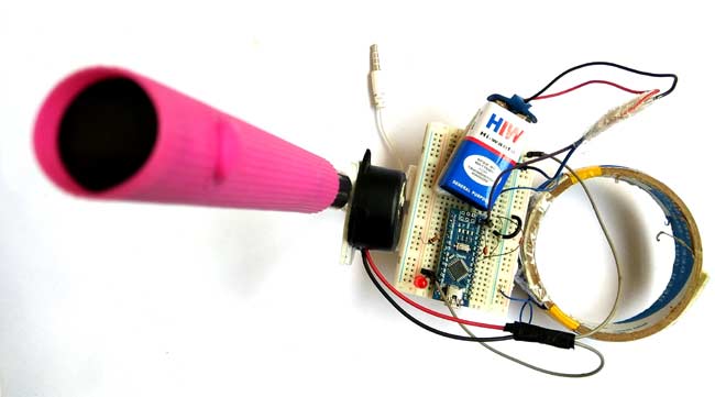
You can view the complete code and demonstration video of Arduino Metal Detector below. You will see that as soon as metal is detected, the LED and buzzer will start flashing quickly.
code
/*

Metal Detector Arduino Code

www.circuitdigest.com

*/

#define capPin A5
#define buz 9
#define pulsePin A4

#define led 10

long sumExpect=0; //running sum of 64 sums
long ignor=0;   //number of ignored sums
long diff=0;        //difference between sum and avgsum
long pTime=0;
long buzPeriod=0;

void setup()
{
  Serial.begin(9600);
  pinMode(pulsePin, OUTPUT);
  digitalWrite(pulsePin, LOW);
  pinMode(capPin, INPUT);
  pinMode(buz, OUTPUT);
  digitalWrite(buz, LOW);
  pinMode(led, OUTPUT);
}

void loop()
{
  int minval=1023;
  int maxval=0;
  long unsigned int sum=0;
  for (int i=0; i<256; i++)
  {
    //reset the capacitor
    pinMode(capPin,OUTPUT);
    digitalWrite(capPin,LOW);
    delayMicroseconds(20);
    pinMode(capPin,INPUT);
    applyPulses();

    //read the charge of capacitor
    int val = analogRead(capPin); //takes 13x8=104 microseconds
    minval = min(val,minval);
    maxval = max(val,maxval);
    sum+=val;

    long unsigned int cTime=millis();
    char buzState=0;
    if (cTime<pTime+10)
    {
      if (diff>0)
        buzState=1;
      else if(diff<0)
        buzState=2;
    }
    if (cTime>pTime+buzPeriod)
    {
      if (diff>0)
      buzState=1;
      else if (diff<0)
      buzState=2;
      pTime=cTime;
    }
    if (buzPeriod>300)
    buzState=0;

    if (buzState==0)
    {
      digitalWrite(led, LOW);
      noTone(buz);
    }
    else if (buzState==1)
    {
      tone(buz,2000);
      digitalWrite(led, HIGH);
    }

    else if (buzState==2)
    {
      tone(buz,500);
      digitalWrite(led, HIGH);
    }
  }

  //subtract minimum and maximum value to remove spikes
  sum-=minval;
  sum-=maxval;

  if (sumExpect==0)
  sumExpect=sum<<6; //set sumExpect to expected value
  long int avgsum=(sumExpect+32)>>6;
  diff=sum-avgsum;
  if (abs(diff)<avgsum>>10)
  {
    sumExpect=sumExpect+sum-avgsum;
    ignor=0;
  }
  else
    ignor++;
  if (ignor>64)
  {
    sumExpect=sum<<6;
    ignor=0;
  }
  if (diff==0)
    buzPeriod=1000000;
  else
  buzPeriod=avgsum/(2*abs(diff));
}

void applyPulses()
{
    for (int i=0;i<3;i++)
    {
      digitalWrite(pulsePin,HIGH); //take 3.5 uS
      delayMicroseconds(3);
      digitalWrite(pulsePin,LOW);  //take 3.5 uS
      delayMicroseconds(3);
    }
}