reference material: https://www.arduino.cn/thread-2423-1-1.html
1. Required materials
- Rotary encoder (KY-040)
- Arduino UNO development board
- LCD character dot matrix 1602
- Potentiometer 10k
- Bread board
2. How does the connecting wire rotary encoder work?
Rotary encoder is an electromechanical transducer, which means that it converts mechanical motion into electronic pulse. It consists of a knob. When rotated, the knob will move step by step and generate a series of pulse sequences, each step having a predefined width. There are many types of encoders. Each encoder has its own working mechanism. We will learn about these types later, but now let's only focus on KY040 incremental encoder because we use it in our tutorial.
The internal mechanical structure of the encoder is shown below. It basically consists of A disc (gray) and A conductive pad (copper) placed on the top of the disc. These conductive pads are placed at the same distance as shown below. The output pin is fixed on the top of the disc so that when the knob rotates, the conductive pad contacts the output pin. There are two output pins, output A and output B, as shown in the figure below.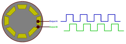
The output waveforms generated by output pin A and output B are displayed in blue and green respectively. When the conductive pad is directly below the pin, it will become higher, resulting in the conduction time. When the conductive pad is removed, the pin will become lower, resulting in the closing time of the waveform shown above. Now, if we calculate the number of pulses, we will be able to determine how many steps the encoder has moved.
Now the question may arise: why do we need two pulse signals when one pulse signal is enough to calculate the number of steps taken when rotating the knob. This is because we need to determine the direction of rotation of the knob. If you look at these two pulses, you will notice that they are 90 ° out of phase. Therefore, when the knob is rotated clockwise, output A will first become high, and when the knob is rotated counterclockwise, output B will first become high.
3. Type of rotary encoder
There are many types of rotary encoders on the market, and design engineers can choose one according to their own applications. The most common types are as follows
- Incremental encoder
- Absolute encoder
- Magnetic Encoder
- Optical encoder
- Laser encoder
These encoders are classified based on output signal and sensing technology, incremental encoder and absolute encoder are classified based on output signal, and magnetic, optical and laser encoder are classified based on sensing technology. The encoder used here is an incremental encoder.
4. KY-040 rotary encoder pin and description
The pin distribution of KY-040 incremental rotary encoder is as follows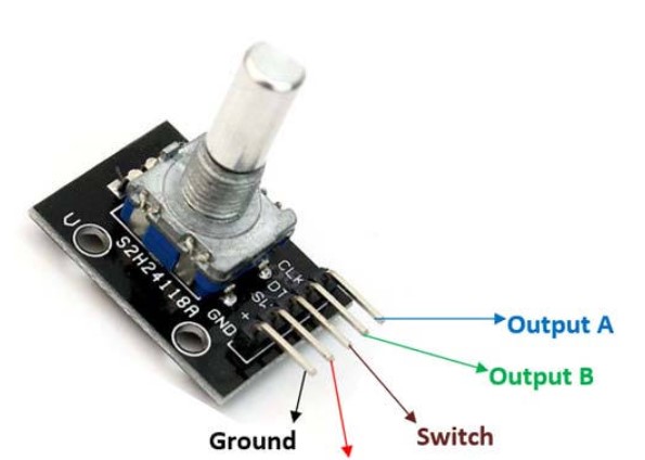
The first two pins (ground and Vcc) are used to power the encoder, usually using a + 5V power supply. In addition to rotating the knob clockwise and counterclockwise, the encoder also has a Switch (low level is effective), which can be pressed by pressing the internal knob. The signal from this Switch is obtained through pin 3 (Switch). Finally, it has two output pins to produce the waveform described above. Now let's learn how to communicate with Arduino Connect.
5. Circuit diagram of connection between Arduino and rotary encoder
The complete circuit diagram of rotary encoder and Arduino connection is shown in the figure below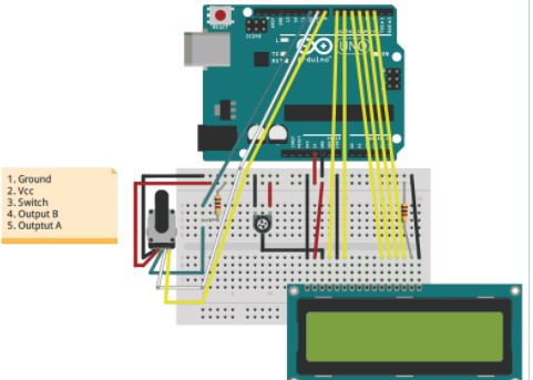
The rotary encoder has 5 pins in the order shown in the label above. The first two pins are ground and Vcc, which are connected to the ground and + 5V pins of Arduino. The switch of the encoder is connected to the digital pin D8 and pulled up through a 1k resistance. The two output pins are connected to D9 and D8 respectively.
To display the variable values increased or decreased by rotating the Rotary encoder, we need a display module. Commonly used here character Graphic dot matrix LCD 1602. We have set the connected display to 4-bit operating mode and powered it using the + 5V pin of Arduino. The potentiometer is used to adjust the contrast of the LCD display. The complete circuit can be built on the bread board. Once all connections are completed, the effect looks similar to the following figure.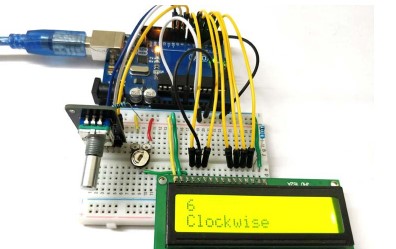
It shows that using the pull-up input inside the single chip microcomputer may bring large power consumption, because the internal resistance of the single chip microcomputer is large. The basic principle of arduino implementation is that when the number of pulses per cycle is known to be 2500, one cycle will be counted when the number of pulses per cycle is 2500. If it is stm32, overflow interrupt will be carried out. Through the high-low level relationship of phase A and phase B, judge the sequence relationship of phase AB, and then judge the steering.
In order to distinguish between forward and reverse rotation and detect zero point, it usually includes three parts: phase a, phase B and phase Z. phase A and phase B differ by 1 / 4 cycle (phase difference 90 degrees), which can be used to distinguish forward rotation or reverse rotation; Phase Z is a single cycle pulse, which is generated once when the code disk rotates once, and can be used as the reference zero position of the encoder, as shown in the following figure: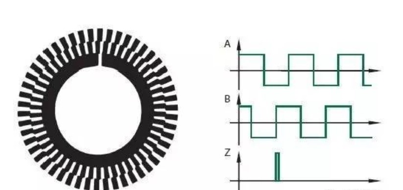
6. Write Arduino program for rotary encoder
If you understand how the rotary encoder works, it is quite easy to program the Arduino development board to connect the rotary encoder to it. We only need to read the number of pulses to determine the rotation number of the encoder, and first check which pulse is high to find the rotation direction of the encoder. In this article, we will display the increased or decreased numbers on the first line of the LCD and the direction of the encoder on the second line.
Because we use an LCD display, we include the LCD library that exists by default in the Arduino IDE. Then we define the pin used to connect the LCD and Arduino. Finally, we initialize the LCD display on these pins.
#include <LiquidCrystal.h> //Default Arduino LCD Library is included
const int rs = 7, en = 6, d4 = 5, d5 = 4, d6 = 3, d7 = 2; //Mention the pin number for LCD connection
LiquidCrystal lcd(rs, en, d4, d5, d6, d7);
lcd.begin(16, 2); //Initialise 16*2 LCD
Next, in the setup function, we display the introduction message on the LCD screen and wait for 2 seconds so that the user can read the message. This is to ensure that the LCD works properly.
#include <LiquidCrystal.h> //Default Arduino LCD Library is included
const int rs = 7, en = 6, d4 = 5, d5 = 4, d6 = 3, d7 = 2; //Mention the pin number for LCD connection
LiquidCrystal lcd(rs, en, d4, d5, d6, d7);
lcd.begin(16, 2); //Initialise 16*2 LCD
Rotary encoder has three output pins, which are input pins for Arduino. The three pins are Switch, Output A and Output B. These pins are declared as input using the pinMode function, as shown below.
//pin Mode declaration
  pinMode (Encoder_OuputA, INPUT);
  pinMode (Encoder_OuputB, INPUT);
  pinMode (Encoder_Switch, INPUT);
In the void setup() function, we read the state of the output A pin to check the last state of the pin. We will then use this information to compare with the new value to check which pin (output A or output B) goes high.
Previous_Output = digitalRead(Encoder_OuputA); //Read the inital value of Output A
Finally, in the loop function, we must compare the values of output A and output B with the previous output to check which goes high first. This can be done by simply comparing the current output values of A and B with the previous output, as shown below.
if (digitalRead(Encoder_OuputA) != Previous_Output)
   {
     if (digitalRead(Encoder_OuputB) != Previous_Output)
     {
       Encoder_Count ++;
       lcd.clear();
       lcd.print(Encoder_Count);
       lcd.setCursor(0, 1);
       lcd.print("Clockwise");
     }
In the above code, if output B has changed from the previous output, the second if condition is executed. In this case, the value of the encoder variable increases and the LCD shows that the encoder rotates in a clockwise direction. Similarly, if the if condition is not met, in other subsequent conditions, we decrement the variable and show that the encoder rotates counterclockwise. The code is shown below.
  else
     {
       Encoder_Count--;
       lcd.clear();
       lcd.print(Encoder_Count);
       lcd.setCursor(0, 1);
       lcd.print("Anti - Clockwise");
     }
   }
Finally, at the end of the loop function, we must update the previous output value with the current output value so that the loop can be repeated with the same logic.
Previous_Output = digitalRead(Encoder_OuputA);
Another option is to check whether the switch on the encoder is pressed. This can be monitored by checking the switch pin on the rotary encoder. This pin is a low active pin, which means that it will become low when the button is pressed. If the pin is not pressed to maintain the high level, we also use a pull-up resistor to ensure that the high level is maintained when the switch is not pressed, so as to avoid floating state.
if (digitalRead(Encoder_Switch) == 0)
   {
     lcd.clear();
     lcd.setCursor(0, 1);
     lcd.print("Switch pressed");
   }
Arduino controls the working process of rotary encoder
Once the hardware and code are ready, just upload the code to the Arduino development board and power the Arduino. You can power it through a USB cable or use a 12V adapter. When powered on, the LCD shall display an introduction message and then become blank. Now rotate the rotary encoder, you should see that the value increases or decreases according to the direction of rotation. The second line shows whether the encoder rotates clockwise or counterclockwise. The following figure shows the actual working process:

In addition, when the button is pressed, the second line displays the pressed button. This is just a sample program for connecting the rotary encoder to Arduino. Check whether it works as expected. You should now be able to use the encoder for any project and program accordingly.
7.3 complete code
#Pindefine / / external interrupt 2
#define PinZ 3 / / external interrupt 1
#define PinB 8 / / encoder out_ The B signal is connected to digital port 8

//Variable initialization
unsigned long time1 = 0; // Time stamp
float time_cw;
float time_ccw;
long count = 0;
const float d = 75.7 / 1000; //Diameter of wheel
const float pi = 3.141592654;//PI
int num = 0;//Number of turns
double t;//One lap exercise time
float velocity;
double time3;//The time when external interrupt 1 is generated, that is, when the zero setting signal of Z phase is captured, it is used to calculate the length of one cycle in the loop cycle

void setup()
{
  pinMode(PinA, INPUT_PULLUP);//Because the encoder signal is Omron E6B2-CWZ6C, which is an open drain output, the pull-up resistance is required. Here, the internal pull-up input mode of arduino is adopted and set high
  pinMode(PinB, INPUT_PULLUP);//ditto
  pinMode(PinZ, INPUT_PULLUP);//ditto
  attachInterrupt(0, Encode, FALLING);//Pulse interrupt function: capture phase a signal and judge the sequence of phase A and phase B
  attachInterrupt(1, Set_state , FALLING);//It is used to set the state to zero when the zero signal of Z is captured

  Serial.begin (9600);
}

void loop()
{
  double distance;
  //Forward rotation
  if (count == 2500)
  {
    //      Serial.println("ok");// Trial adjustment
    num = num + 1;
    time_cw = millis();
    t = time_cw - time3;
    t = t / 1000;
    distance = num * d * pi;
    velocity = d * pi / t;
    Serial.print("The wheel has run ");
    Serial.print(distance);
    Serial.println("m.");
    Serial.print("The cw_speed is ");
    Serial.print(velocity);
    Serial.println("m/s.");
    Serial.print("The time is ");
    Serial.print(t);
    Serial.println("s.");
  }
  //reversal
  if (count == -2500)
  {
    //      Serial.println("ok");// Trial adjustment
    num = num + 1;
    time_ccw = millis();
    t = time_ccw - time3;
    t = t / 1000;
    distance = num * d * pi;
    velocity = d * pi / t;
    Serial.print("The wheel has run ");
    Serial.print(distance);
    Serial.println("m.");
    Serial.print("The ccw_speed is ");
    Serial.print(velocity);
    Serial.println("m/s.");
    Serial.print("The time is ");
    Serial.print(t);
    Serial.println("s.");
  }
}

// Encoder count interrupt subroutine

void Encode()
{
  //To exclude noise interference pulses,
  //When the time between two interrupts is greater than 5ms, count an effective count
  if ((millis() - time1) > 5)
  {
    //When the OUTA pulse signal of the encoder code disk is interrupted every time,
    if ((digitalRead(PinA) == LOW) && (digitalRead(PinB) == HIGH))
    {
      count--;
    }
    else
    {
      count++;
    }
  }
  time1 == millis();
}
void Set_state() {
  count = 0;
  time3 = millis();//Time when the interruption occurred
}
8. Add the codes of other netizens
#define PinA 2 / / external interrupt 0
#define PinZ 3 / / external interrupt 1
#define PinB 8 / / encoder out_ The B signal is connected to digital port 8

//Variable initialization
unsigned long time1 = 0; // Time stamp
float time_cw;
float time_ccw;
long count = 0;
const float d = 75.7 / 1000; //Diameter of wheel
const float pi = 3.141592654;//PI
int num = 0;//Number of turns
double t;//One lap exercise time
float velocity;
double time3;//The time when external interrupt 1 is generated, that is, when the zero setting signal of Z phase is captured, it is used to calculate the length of one cycle in the loop cycle

void setup()
{
  pinMode(PinA, INPUT_PULLUP);//Because the encoder signal is Omron E6B2-CWZ6C, which is an open drain output, the pull-up resistance is required. Here, the internal pull-up input mode of arduino is adopted and set high
  pinMode(PinB, INPUT_PULLUP);//ditto
  pinMode(PinZ, INPUT_PULLUP);//ditto
  attachInterrupt(0, Encode, FALLING);//Pulse interrupt function: capture phase a signal and judge the sequence of phase A and phase B
  attachInterrupt(1, Set_state , FALLING);//It is used to set the state to zero when the zero signal of Z is captured

  Serial.begin (9600);
}

void loop()
{
  double distance;
  //Forward rotation
  if (count == 2500)
  {
    //      Serial.println("ok");// Trial adjustment
    num = num + 1;
    time_cw = millis();
    t = time_cw - time3;
    t = t / 1000;
    distance = num * d * pi;
    velocity = d * pi / t;
    Serial.print("The wheel has run ");
    Serial.print(distance);
    Serial.println("m.");
    Serial.print("The cw_speed is ");
    Serial.print(velocity);
    Serial.println("m/s.");
    Serial.print("The time is ");
    Serial.print(t);
    Serial.println("s.");
  }
  //reversal
  if (count == -2500)
  {
    //      Serial.println("ok");// Trial adjustment
    num = num + 1;
    time_ccw = millis();
    t = time_ccw - time3;
    t = t / 1000;
    distance = num * d * pi;
    velocity = d * pi / t;
    Serial.print("The wheel has run ");
    Serial.print(distance);
    Serial.println("m.");
    Serial.print("The ccw_speed is ");
    Serial.print(velocity);
    Serial.println("m/s.");
    Serial.print("The time is ");
    Serial.print(t);
    Serial.println("s.");
  }
}

// Encoder count interrupt subroutine

void Encode()
{
  //To exclude noise interference pulses,
  //When the time between two interrupts is greater than 5ms, count an effective count
  if ((millis() - time1) > 5)
  {
    //When the OUTA pulse signal of the encoder code disk is interrupted every time,
    if ((digitalRead(PinA) == LOW) && (digitalRead(PinB) == HIGH))
    {
      count--;
    }
    else
    {
      count++;
    }
  }
  time1 == millis();
}
void Set_state() {
  count = 0;
  time3 = millis();//Time when the interruption occurred
}