catalogue
1, Hardware usage classification
2.STM32F103RCT6 single chip microcomputer
1, Hardware usage classification
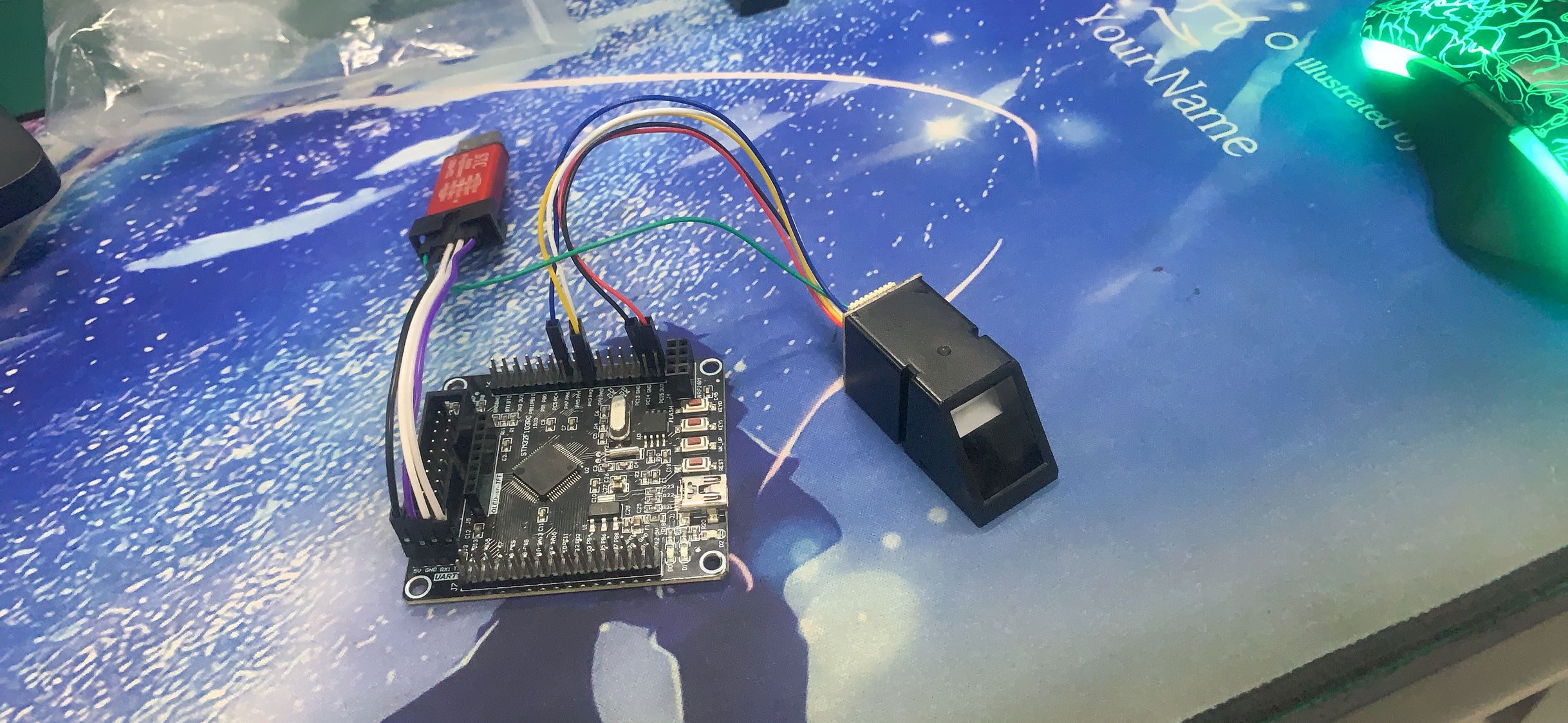
1. Overall drawing display
STM32F103RCT6 is used as the main controller
2.STM32F103RCT6 single chip microcomputer
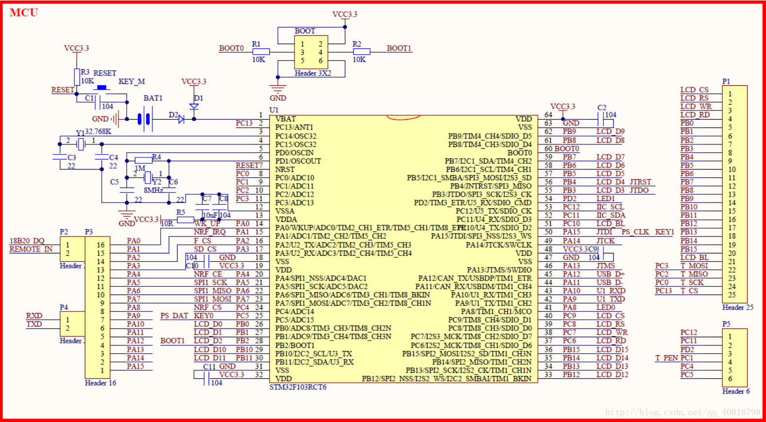
STM32F103RCT6 does not contain USB to TTL chip and requires external access
The following figure shows the schematic diagram of STM32F103RCT6
In RCT6, PA9 and PA10 are USART1 of the board. The above two pins do not appear in the schematic diagram, and their pins are TX and Rx marked on the board
The following is the initialization program design of USART1 in the project
void uart_init(u32 bound)
	{
  //GPIO port settings
    GPIO_InitTypeDef GPIO_InitStructure;
	USART_InitTypeDef USART_InitStructure;
	NVIC_InitTypeDef NVIC_InitStructure;

	RCC_APB2PeriphClockCmd(RCC_APB2Periph_USART1|RCC_APB2Periph_GPIOA, ENABLE);	//Enable USART1, GPIOA clock

	//USART1_TX   GPIOA.9
  GPIO_InitStructure.GPIO_Pin = GPIO_Pin_9; //PA.9
  GPIO_InitStructure.GPIO_Speed = GPIO_Speed_50MHz;
  GPIO_InitStructure.GPIO_Mode = GPIO_Mode_AF_PP;	//Multiplexed push-pull output
  GPIO_Init(GPIOA, &GPIO_InitStructure);//Initialize gpioa nine

  //USART1_RX 	   GPIOA.10 initialization
  GPIO_InitStructure.GPIO_Pin = GPIO_Pin_10;//PA10
  GPIO_InitStructure.GPIO_Mode = GPIO_Mode_IN_FLOATING;//Floating input
  GPIO_Init(GPIOA, &GPIO_InitStructure);//Initialize gpioa ten

  //Usart1 NVIC configuration
  NVIC_InitStructure.NVIC_IRQChannel = USART1_IRQn;
	NVIC_InitStructure.NVIC_IRQChannelPreemptionPriority=3 ;//Preemption priority 3
	NVIC_InitStructure.NVIC_IRQChannelSubPriority = 3;		//Sub priority 3
	NVIC_InitStructure.NVIC_IRQChannelCmd = ENABLE;			//IRQ channel enable
	NVIC_Init(&NVIC_InitStructure);	//Initializes the VIC register according to the specified parameters

   //USART initialization settings

	USART_InitStructure.USART_BaudRate = bound;//Serial baud rate
	USART_InitStructure.USART_WordLength = USART_WordLength_8b;//The word length is in 8-bit data format
	USART_InitStructure.USART_StopBits = USART_StopBits_1;//A stop bit
	USART_InitStructure.USART_Parity = USART_Parity_No;//No parity bit
	USART_InitStructure.USART_HardwareFlowControl = USART_HardwareFlowControl_None;//No hardware data flow control
	USART_InitStructure.USART_Mode = USART_Mode_Rx | USART_Mode_Tx;	//Transceiver mode

  USART_Init(USART1, &USART_InitStructure); //Initialize serial port 1
  USART_ITConfig(USART1, USART_IT_RXNE, ENABLE);//Open serial port to accept interrupt
  USART_Cmd(USART1, ENABLE);                    //Enable serial port 1

}
In the above program section, we can clearly see that PA9 and PA10 can be used. PA9 is TX and PA10 is RX.
3.AS608 fingerprint module
AS608 fingerprint identification module is a high-performance optical fingerprint identification module launched by ALIENTEK. AS608 module adopts AS608 fingerprint identification chip of Hangzhou Shengyuan Chip Technology Co., Ltd. (Synochip), a famous domestic fingerprint identification chip company. The chip has built-in DSP operation unit and integrated fingerprint identification algorithm, which can efficiently and quickly collect images and identify fingerprint features. The module is equipped with serial port and USB communication interface. Users do not need to study complex image processing and fingerprint recognition algorithms. They can control the module through simple serial port and USB according to the communication protocol. This module can be applied to various attendance machines, safes, fingerprint access control systems, fingerprint locks and other occasions.
The following are some specific parameters of AS608:
| Supply voltage | 3.3V (do not use 5V, it is easy to burn the chip) |
| Supply current | < 60mA |
| Fingerprint image input time | < 1s |
| Search time | < 1.0s (mean value at 1:500) |
| Number of fingerprints that can be entered | 300 |
| communication interface | USB/USART |
| Matching mode | Comparison method (1:1), search method (1:N) |
Attention!!!! AS608 fingerprint module must be connected to 3.3V instead of 5V
Attention!!!! AS608 fingerprint module must be connected to 3.3V instead of 5V
Attention!!!! AS608 fingerprint module must be connected to 3.3V instead of 5V
If you don't believe it, you can try it (if you are a local tyrant, skip this one completely)
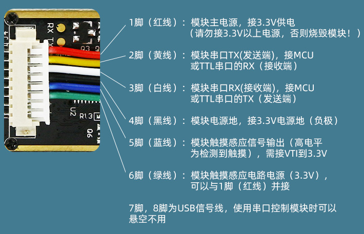
The following two figures are the pin explanations of our AS608 fingerprint module:
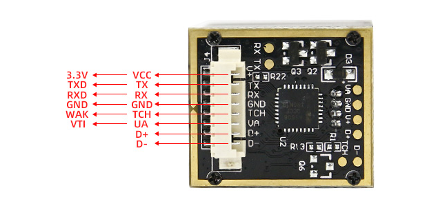
D + and D - don't need to be connected. Even if you want to connect, you may not be able to connect. Anyway, there are no pins for those two wires.
The 5-wire (blue wire) pin is our output pin. In other words, each module is just a switch in the end, that is, the starting mode of the switch is different.
4.USB to TTL
I won't introduce this too much. It's all commonly used.
2, Software design
1. Wiring design
Wiring between AS608 fingerprint module and MCU
| VCC | GND | TX | RX | TCH | UA |
| 3.3V | GND | PA3 | PA4 | PA6 | 3.3V |
USB to TTL and MCU wiring
| VCC | GND | TX | RX |
| 5V | GND | RX(PA10) | TX(PA9) |
In RCT6, TX and RX are identified. In fact, they are PA10 and PA9 on the single chip microcomputer. They have been explained above. I won't explain too much here.
2. Program design
The program is modified according to the history in the punctual atom. Here, the serial port is used for operation
For AS608 fingerprint module, we first have to shake hands. In other words, we connect the MCU with the module by sending specific hexadecimal data.
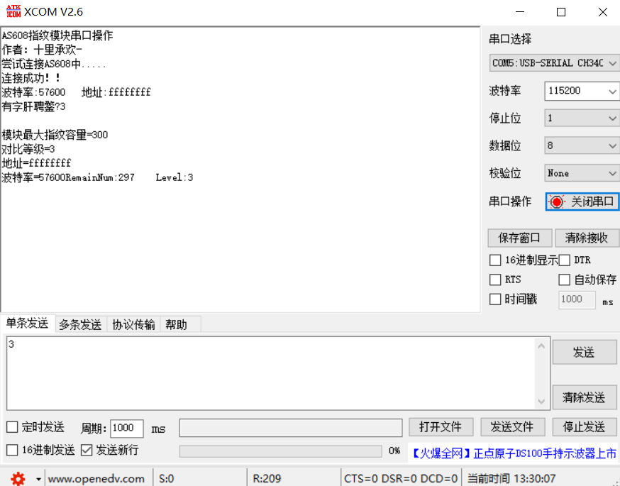
printf("AS608 Fingerprint module serial port operation\r\n");
	printf("Author: Shili chenghuan-\r\n");
	printf("Try to connect AS608 in.....\r\n");
	while(PS_HandShake(&AS608Addr))//Handshake with AS608 module
	{

		printf("Not connected AS608!\r\n");
		delay_ms(1000);
		printf("Trying to connect again....\r\n");
		delay_ms(1000);
	}
	//The module was successfully connected and initialized
	printf("Connection succeeded!!\r\n");
	str=mymalloc(30);
	sprintf(str,"Baud rate:%d   address:%x",usart2_baund,AS608Addr);//Display baud rate
	printf("%s",str);
	delay_ms(100);
During the handshake
1. Send packet header: that is, 0XEF and 0X01
2. Sending address: the default address of AS608 is 0xfffffff
3. Send 0X01, 0X00 and 0X00 to wait for the AS608 response, and compare the response data to complete the handshake
//Shake hands with AS608 PS_HandShake
//Parameter: PS_Addr address pointer
//Description: module return new address (correct address)
u8 PS_HandShake(u32 *PS_Addr)
{
	SendHead();
	SendAddr();
	MYUSART_SendData(0X01);
	MYUSART_SendData(0X00);
	MYUSART_SendData(0X00);
	delay_ms(200);
	if(USART2_RX_STA&0X8000)//Data received
	{
		if(//Determine whether it is the response packet returned by the module
					USART2_RX_BUF[0]==0XEF
				&&USART2_RX_BUF[1]==0X01
				&&USART2_RX_BUF[6]==0X07
			)
			{
				*PS_Addr=(USART2_RX_BUF[2]<<24) + (USART2_RX_BUF[3]<<16)
								+(USART2_RX_BUF[4]<<8) + (USART2_RX_BUF[5]);
				USART2_RX_STA=0;
				return 0;
			}
		USART2_RX_STA=0;
	}

	return 1;
}
Then follow the prompts
Press KEY1 to enter the fingerprint
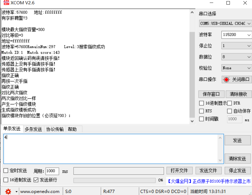
At this time, we need to fill in the location of fingerprints. Since the module can store up to 300 fingerprints, the location is any number from 1 to 300.
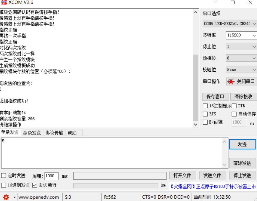
Our fingerprints have been successfully entered.
We can read fingerprints:
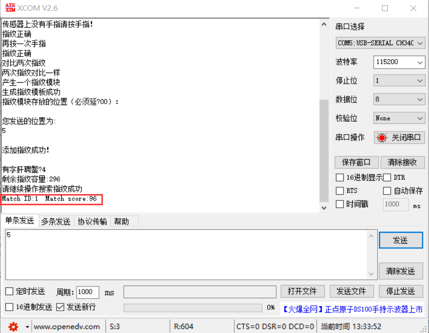
In the red frame, the front is our fingerprint position, and the back is our level, that is, the degree of similarity, which can be understood in this way.
The remaining functions are not much to demonstrate. Basically, there is no problem following the prompts.
I hope you have a good look at the user manual. I put the link below:
https://pan.baidu.com/s/1HoqaqClOjuoHO5D-bHeUJA Extraction code: dte5
Program link: https://pan.baidu.com/s/1v7yOCNp82kGRC_9qrAQGEA Extraction code: jm7p
I also said above that a series of operations and expansion can be carried out through TCH pin. I hope you can refuel!!!!!