catalogue
Case background and requirements
Add VRRP configuration on router interface
Check VRRP connectivity and access path
Configure VRRP tracking uplink port
Case background and requirements
In an enterprise network topology shown in the figure, routers R1 and R2 are two routers connecting the enterprise Gateway (GW), and the GW is connected to the Internet through LSP (here I use Server1 instead)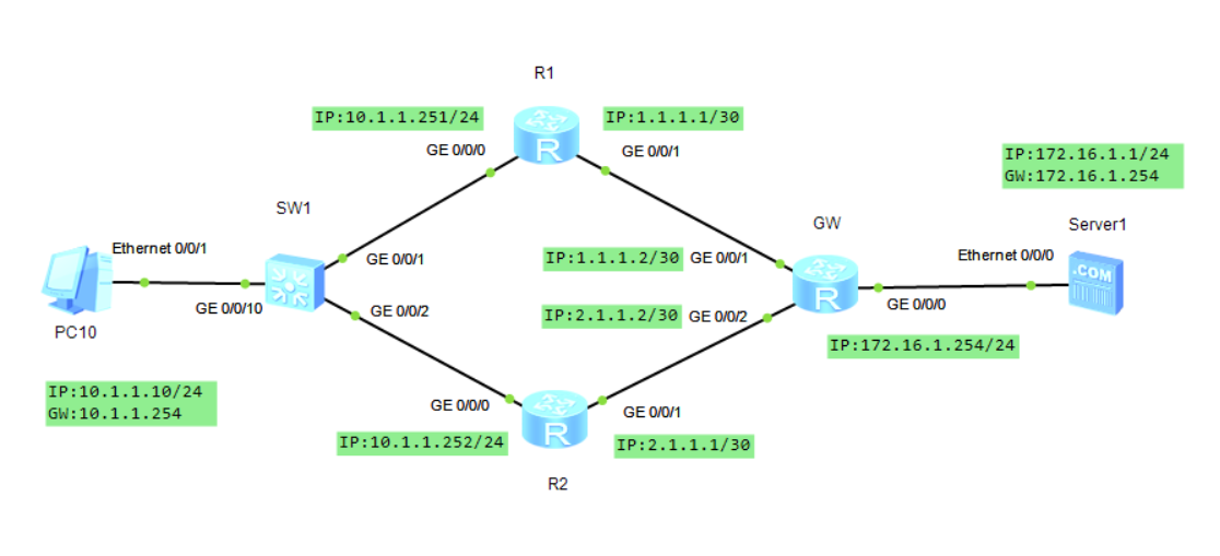
The enterprise network requires the administrator to use VRRP to realize the route backup of routers R1 and R2, so as to improve the reliability of external network access. By default, router R1 is the main router, router R2 is the standby router, and internal users of the enterprise (see figure PC10) use the IP address (10.1.1.254) of the virtual router as the gateway address.
Case interface and address pool planning
The interface and IP address plan are marked in the topology diagram
Case configuration process
Configuration interface
[R1]interface GigabitEthernet 0/0/0
[R1-GigabitEthernet0/0/0]ip address 10.1.1.251 24
[R1-GigabitEthernet0/0/0]int g0/0/1
[R1-GigabitEthernet0/0/1]ip address 1.1.1.1 30
[R2]interface GigabitEthernet 0/0/0
[R2-GigabitEthernet0/0/0]ip address 10.1.1.252 24
[R2-GigabitEthernet0/0/0]int g0/0/1
[R2-GigabitEthernet0/0/1]ip address 2.1.1.1 30
[GW]interface GigabitEthernet 0/0/0
[GW-GigabitEthernet0/0/0]ip address 172.16.1.254 24
[GW-GigabitEthernet0/0/0]int g0/0/1
[GW-GigabitEthernet0/0/1]ip address 1.1.1.2 30
[GW-GigabitEthernet0/0/1]int g0/0/2
[GW-GigabitEthernet0/0/2]ip address 2.1.1.2 30
Configure static routing
[R1]ip route-static 172.16.1.0 24 1.1.1.2
[R2]ip route-static 172.16.1.0 24 2.1.1.2
[GW]ip route-static 10.1.1.0 24 1.1.1.1
[GW]ip route-static 10.1.1.0 24 2.1.1.1
Add VRRP configuration on router interface
In this case, the administrator is required to set the virtual router ID (VRID) of VRRP to 10, set the virtual router IP address to 10.1.1.254, and make router R1 the primary router of VRRP and router R2 the standby router of VRRP.
[R1]interface GigabitEthernet 0/0/0
[R1-GigabitEthernet0/0/0]vrrp vrid 10 virtual-ip 10.1.1.254
[R1-GigabitEthernet0/0/0]vrrp vrid 10 priority 150
[R2]interface GigabitEthernet 0/0/0
[R2-GigabitEthernet0/0/0]vrrp vrid 10 virtual-ip 10.1.1.254
Check VRRP status
[R1]display vrrp brief
Total:1     Master:1     Backup:0     Non-active:0
VRID  State        Interface                Type     Virtual IP
----------------------------------------------------------------
10    Master       GE0/0/0                  Normal   10.1.1.254
[R2]display vrrp brief
Total:1     Master:0     Backup:1     Non-active:0
VRID  State        Interface                Type     Virtual IP
----------------------------------------------------------------
10    Backup       GE0/0/0                  Normal   10.1.1.254
View VRRP version
[R1]display vrrp protocol-information
 VRRP protocol information is shown as below:
    VRRP protocol version : V2
    Send advertisement packet mode : send v2 only
Check VRRP connectivity and access path
PC>ping 172.16.1.1

Ping 172.16.1.1: 32 data bytes, Press Ctrl_C to break
From 172.16.1.1: bytes=32 seq=1 ttl=253 time=31 ms
From 172.16.1.1: bytes=32 seq=2 ttl=253 time=47 ms
From 172.16.1.1: bytes=32 seq=3 ttl=253 time=31 ms
From 172.16.1.1: bytes=32 seq=4 ttl=253 time=31 ms
From 172.16.1.1: bytes=32 seq=5 ttl=253 time=47 ms

--- 172.16.1.1 ping statistics ---
  5 packet(s) transmitted
  5 packet(s) received
  0.00% packet loss
  round-trip min/avg/max = 31/37/47 ms

PC>tracert 172.16.1.1

traceroute to 172.16.1.1, 8 hops max
(ICMP), press Ctrl+C to stop
 1  10.1.1.251   46 ms  47 ms  32 ms
 2  1.1.1.2   63 ms  47 ms  46 ms
 3  172.16.1.1   32 ms  47 ms  46 ms

PC>
From the output result of the [tracert] command, it can be confirmed that the path of data packet transmission is PC10 → R1 → GW
Configure VRRP tracking uplink port
[R1]interface GigabitEthernet 0/0/0
[R1-GigabitEthernet0/0/0]vrrp vrid 10 track interface GigabitEthernet 0/0/1 reduced 100
It can be seen from the configuration command that router R1 should track the status of interface GE0/0/1 in VRRP VRID 10. When the status of GE0/0/1 changes to Down, reduce the priority of VRRP VRID 10 by 100 (at this time, the priority of router R1 interface GE0/0/0 is 50, which is lower than that of router R2 interface GE0/0/0), so that router R2 can seize the primary role through priority.
Manually close the interface GE0/0/1 of router R1
[R1]interface GigabitEthernet 0/0/1
[R1-GigabitEthernet0/0/1]shutdown
Verification effect
PC>tracert 172.16.1.1

traceroute to 172.16.1.1, 8 hops max
(ICMP), press Ctrl+C to stop
 1  10.1.1.252   47 ms  47 ms  47 ms
 2  2.1.1.2   47 ms  31 ms  47 ms
 3  172.16.1.1   47 ms  46 ms  47 ms

PC>
From the path tracking echo information, it is clear that PC10 has started to access the Internet through the GE0/0/0 interface of router R2. Therefore, the main / standby router of VRRP has been switched successfully.
summary
The above is the basic configuration of VRRP I sorted out. If there is any error, please point out the communication (* this article is created for the first time)