colony
Cluster overview
What is a cluster
- A group of computers interconnected through a high-speed network and managed in a single system mode
- Many servers come together to provide the same service, which looks like a server to the client
- Relatively high benefits in performance, reliability and flexibility can be obtained at a lower cost
- Task scheduling is the core technology in cluster system
Purpose of cluster
-
Improve performance
Such as computing intensive applications, such as weather forecasting and nuclear test simulation
-
cost reduction
Compared with the million level supercomputer, the price is cheap
-
Improve scalability
Just add cluster nodes
-
Improve reliability
Multiple nodes complete the same function to avoid single point of failure
Cluster classification
-
High performance computing cluster HPC
Through the parallel application of cluster card method, complex scientific problems are solved
-
Load balancing (LB) cluster
The client load is shared equally in the computer cluster as much as possible
-
High availability (HA) cluster
Avoid single point of failure. When a system fails, it can migrate quickly
The software that meets the above requirements includes LVS, keepalived, etc
LVS project introduction
- Linux virtual server (LVS) was created by Zhang Wenhao during his doctoral study at the University of national defense science and technology
- LVS can realize highly available and scalable web, Mail, Cache, Media and other network services
- The ultimate goal is to use Linux operating system and LVS cluster software to realize a server application cluster with high availability, high performance and low cost
- The software is built into the Linux kernel
LVS cluster composition
-
Front end: load balancing layer
It consists of one or more load schedulers
-
Middle: server group layer
It consists of a group of servers that actually run application services
-
Bottom: data sharing storage layer
A storage area that provides shared storage
Common terms for LVS
-
Director Server: scheduling server
Distribute the load to the Real Server server
There are two IPS, one is VIP and the other is DIP
-
Real Server: Real Server
Real application server (RIP)
-
VIP: virtual IP address
The virtual IP address published to the user for access (generally the IP address of the scheduler)
-
RIP: real IP address
IP addresses used on cluster nodes
-
DIP: the IP address of the server to which the scheduler connects
Operating mode of LVS
The principle of lvs is router (packet forwarding)
Workflow: the client accesses lvs, lvs forwards the data packet to the web server, and the web server responds to the data packet to the client
nginx principle as agent (help customers access)
Workflow: the client accesses the nginx proxy server. The proxy server helps the client access the web server. The web server returns the content to the nginx proxy server and returns it to the client through the proxy server
Compared with routers, lvs has one more scheduling function, which is the core of the cluster
lvs is something at the kernel level. Compared with nginx (nginx is software at the operating system level), lvs has higher performance, but it has fewer functions, such as lack of health check

NAT mode:
The user accesses the scheduler, the scheduler forwards the request to web1, and web1 replies to the user from the scheduler
When users access too much, all data will pass through the scheduler. At this time, the network bandwidth will become the bottleneck of the whole cluster. This is suitable for small-scale clusters
- Virtual server realized by network address translation
- In case of large concurrent access, the performance of the scheduler becomes a bottleneck
TUN mode:
The scheduler and the server are not on the same network. For example, the user accesses the scheduler with address A, and the scheduler forwards it to the web server with address B, which crosses the public network. Therefore, A tunnel should be built between the proxy server and the web server
- Realize virtual server through tunnel
DR mode: (direct routing mode)
The user accesses the scheduler, the scheduler forwards it to the web server, and the web server replies directly to the user
This mode alleviates the pressure of data returned by the scheduler, improves the amount of concurrent access, and is suitable for large-scale clusters
- Direct use of routing technology to implement virtual server
- The node server needs to be configured with VIP. Pay attention to the MAC address broadcast
LVS load balancing scheduling algorithm
-
LVS currently implements 10 scheduling algorithms
-
There are four common scheduling algorithms
Polling (rr): distributes client requests evenly to the Real Server
Weighted polling (wrr): performs polling scheduling according to the weight value of Real Server
Least connection (lc): select the server with the least number of connections
Weighted least connection (wlc): select the server with the least number of connections according to the weight value of Real Server
-
Other scheduling algorithms
Source address hashing algorithm: (sh) according to the requested target IP address, it is statically allocated to the Hash list as a Hash Key to find the corresponding server, which is the same as the IP address in nginx_ The hash effect is consistent (the client IP remains unchanged, and there are fixed servers in the server cluster to respond)
Least connection based on locality
Locality based least join with replication
Destination address hash (dh)
Shortest expected delay
Least queue scheduling
LVS-NAT cluster:
The IP load balancing technology of LVS is realized through IPVS module. Here, you need to use ipvsadm command
Before the experiment here
ipvsadm command usage
Question:
Use the Linux server, install the ipvsadm software package, and practice using the ipvsadm command to achieve the following functions
- Use the command to add some TCP based cluster services
- Add several back-end real servers to the cluster
- Implement some client access, and the scheduler allocates fixed servers
- ipvsadm will be used to add, delete and modify rules
- Save ipvsadm rules
Scheme:
Install ipvsadm package
The common ipvsadm command syntax is as follows
| Command options | meaning |
|---|---|
| ipvsadm -A | Add virtual server |
| ipvsadm -E | Modify virtual server |
| ipvsadm -D | Delete virtual server |
| ipvsadm -C | Empty all |
| ipvsadm -a | Add real server |
| ipvsadm -e | Modify real server |
| ipvsadm -d | Delete real server |
| ipvsadm -L | View LVS rule table |
| -s [rr|wrr|lc|wlc|sh] | Specify cluster algorithm |
example
| command | meaning |
|---|---|
| ipvsadm -A -t|u 192.168.19.10:80 -s [algorithm] | Add a virtual server. The protocol is tcp (- t) or udp (- u) |
| ipvsadm -E -t|u 192.168.19.10:80 -s [algorithm] | Modify the virtual server to tcp (- t) or udp (- u) |
| ipvsadm -D -t|u 192.168.19.10:80 | Delete the virtual server. The protocol is tcp (- t) or udp (- u) |
| ipvsadm -C | Empty all |
| ipvsadm -a -t|u 192.168.19.10:80 -r 192.168.20.10 [-g|i|m] [-w weight] | Add real server - g(DR mode) - i (tunnel mode) - m (NAT mode) |
| ipvsadm -e -t|u 192.168.19.10:80 -r 192.168.20.10 [-g|i|m] [-w weight] | Modify real server |
| ipvsadm -d -t|u 192.168.19.10:80 -r 192.168.20.10 | Delete real server |
| ipvsadm -Ln | View the rule table of LVS |
Step: use the command to add, delete and modify LVS cluster rules
1) Create LVS virtual cluster server (algorithm is weighted polling: wrr)
yum -y install ipvsadm   #Install the corresponding software package first
ipvsadm -A -t 192.168.19.130:80 -s wrr
ipvsadm -L
ipvsadm -Ln  #Display in numbers

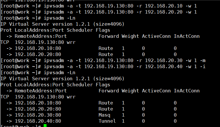
2) Add several real servers to the cluster
ipvsadm -a -t 192.168.19.130:80 -r 192.168.20.10 -w 1
ipvsadm -a -t 192.168.19.130:80 -r 192.168.20.20 -w 1
ipvsadm -Ln
ipvsadm -a -t 192.168.19.130:80 -r 192.168.20.30 -w 1 -m #Using nat mode
ipvsadm -a -t 192.168.19.130:80 -r 192.168.20.40 -w 1 -i #Use tunnel mode
#The default is dr mode
ipvsadm -Ln
#You can see the type in forward. router is dr mode, masq is nat mode, and tunnel is tunnel mode
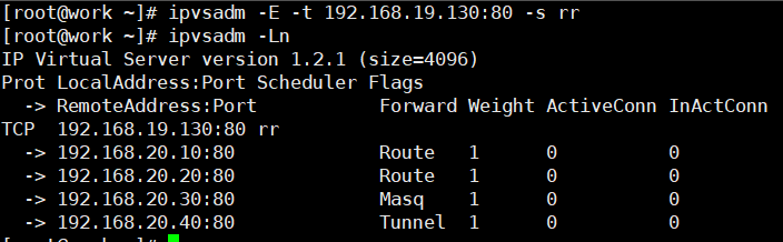
3) Modify cluster server settings (modify scheduler algorithm and change weighted polling to polling)
ipvsadm -E -t 192.168.19.130:80 -s rr
ipvsadm -Ln
#ipvsadm -e can modify the weight and working mode
4) Modify the Read server (use the - g option to change the mode to DR mode)
ipvsadm -e -t 192.168.19.130:80 -r 192.168.20.10 -g
5) View LVS status
ipvsadm -Ln
6) Create another cluster (the algorithm is the least connected algorithm: use - m and set the working mode to NAT mode)
ipvsadm -A 	192.168.19.100:80 -s lc
ipvsadm -a -t 192.168.19.100:80 -r 192.168.20.30 -m
ipvsadm -a -t 192.168.19.100:80 -r 192.168.20.40 -m
7) Permanently save all rules
ipvsadm-save -n > /etc/sysconfig/ipvsadm-config
#In version 7, this configuration file is ipvsadm
8) Clear all rules
ipvsadm -C #In the following experiment, remember to empty the exercise we just did
Deploy LVS-NAT cluster
Question:
Using LVS to implement NAT mode cluster scheduling server to provide users with web services
- The cluster's external public network IP address is 192.168.19.130
- The internal network IP address of the scheduler is 192.168.20.100
- The real web server addresses are 192.168.20.10 and 192.168.20.20 respectively
- Using the weighted polling scheduling algorithm, the real server weights are 1 and 2 respectively
Scheme:
The experimental topology host configuration is as follows
| host name | IP address |
|---|---|
| client | 192.168.19.1/24 |
| proxy | eth0 : 192.168.19.30/24 |
| eth1: 192.168.20.30/24 | |
| web1 | 192.168.20.10 gateway: 192.168.20.30 |
| web2 | 192.168.20.20 gateway: 192.168.20.30 |
Note: the gateway of the real server should be set as the IP address of the lvs connecting to the real host, otherwise the forwarding will fail
Four virtual machines are required, one as the Director scheduler, two as the Real Server server and one as the client. The topology is as follows
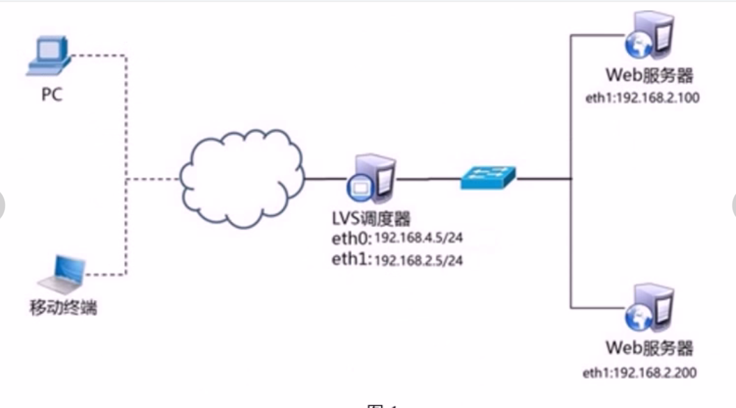
The specific IP shall be subject to the table
Steps:
Step 1: configure the basic environment
1) Deployment infrastructure
web1
yum -y install httpd
echo "web1 I'm 192.168.20.10" > /var/www/html/index.html

web2
yum -y install httpd
echo "web2 I'm 192.168.20.20" > /var/www/html/index.html
2) Start the web server software (web1 and web2 operate simultaneously)
systemctl start httpd
3) Turn off firewall and SELinux (web1 and web2 operate simultaneously)
systemctl stop firewalld
setenforce 0
4) Test web page
Step 2: deploy LVS-NAT mode scheduler
1) Confirm the route forwarding function of the scheduler (if it is enabled, it can be ignored)
echo 1  > /proc/sys/net/ipv4/ip_forward
cat /proc/sys/net/ipv4/ip_forward
echo "net.ipv4.ip_forward = 1" >> /etc/sysctl.conf #Modify the configuration file and set permanent rules
2) Create cluster server
yum -y install ipvsadm
ipvsadm -A -t 192.168.19.30:80 -s wrr  #Create virtual server
3) Add real server
ipvsadm -a -t 192.168.19.30:80 -r 192.168.20.10:80 -w 1 -m
ipvsadm -a -t 192.168.19.30:80 -r 192.168.20.20:80 -w 1 -m
4) View the rule table and save the rule
ipvsadm -Ln
ipvsadm-save -n > /etc/sysconfig/ipvsadm-config #Permanent save rule
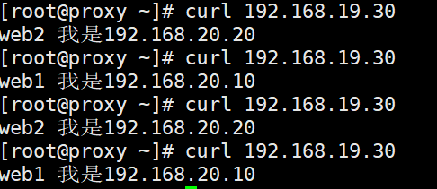
5) Client test
LVS-DR cluster
Question:
- The cluster scheduling server in DR mode is used to provide web services for users:
- The client IP address is 192.168.4.1
- The VIP address of LVS scheduler is 192.168.4.15
- The DIP address of LVS scheduler is set to 192.168.4.5
- The real web server addresses are 192.168.4.100 and 192.168.4.200 respectively
- Using the weighted polling scheduling algorithm, the weight of web1 is 1 and the weight of web2 is 2
explain:
CIP is the IP address of the client
VIP is the IP address that provides services to clients
RIP is the real IP address of the back-end server
DIP is the IP address where the scheduler communicates with the back-end server (VIP must be configured on the virtual interface)
Scheme:
Four virtual machines are used, one as the client, one as the Director scheduler and two as the Real Server. The topology is as follows,

| host name | network configuration |
|---|---|
| client | eth0 192.168.4.1/24 |
| proxy | eth0 192.168.4.5/24 |
| eth0: 0 192.168.4.15/24 | |
| web1 | eth0 192.168.4.100/24 |
| lo: 0 192.168.4.15/32 # note that the subnet mask must be 32 bits | |
| web2 | eth0 192.168.4.200/24 |
| lo: 0 192.168.4.15/32 # note that the subnet mask must be 32 bits |
Steps:
Step 1: configure the experimental network environment
1) Note: in order to prevent conflicts, the VIP must be configured on the virtual interface of the network card
In order to complete the experiment, I cleared the network configuration and reconfigured it to prevent address conflict
Network configuration of proxy
nmcli connection add type ethernet con-name ens192 ifname ens192
nmcli connection modify ens192 ipv4.add 192.168.4.5/24 ipv4.dns 114.114.114.114 ipv4.gateway 192.168.4.2 ipv4.method manual
nmcli connection up ens192

nmcli connection add type ethernet con-name ens224 ifname ens224
nmcli connection modify ens224 ipv4.add 192.168.4.15/24 ipv4.dns 114.114.114.114 ipv4.gateway 192.168.4.2 ipv4.method manual
nmcli connection up ens224
2) Set web1 server network parameters
nmcli connection add type ethernet con-name ens192 ifname ens192
nmcli connection modify ens192 ipv4.add 192.168.4.100/24 ipv4.dns 114.114.114.114 ipv4.gateway 192.168.4.2 ipv4.method manual
nmcli connection up ens192
Next, configure the VIP address for web1
Note: the subnet mask here must be 32 (that is, all 255). The network address is the same as the IP address, and the broadcast address is the same as the IP address
web1
ifconfig lo:10 192.168.4.15 netmask 255.255.255.255 broadcast 192.168.4.15 up
Address conflict prevention
Here, because web1 is also configured with the same VIP address as the agent, address conflicts will certainly occur by default; sysctl. The main purpose of writing the conf file into the following four lines is to access the data packets of 192.168.4.15. Only the scheduler will respond, and no other host will respond. This also prevents the problem of address conflict
web1
vim /etc/sysctl.conf
net.ipv4.conf.all.arp_ignore=1  #All network cards
net.ipv4.conf.lo.arp_ignore=1     #lo loopback ignores arp request packets
net.ipv4.conf.lo.arp_announce=2
net.ipv4.conf.all.arp_announce=2
#arp_ignore ignores ARP request packets
#arp_ Announcement declaration
#Modify kernel parameters and turn off arp response
#When an ARP broadcast asks who is 192.168.4.15, the machine ignores the ARP broadcast
#Do not announce that your lo loopback address is 192.168.4.15
sysctl -p   #Refresh parameters
Restart the network service, set up the firewall and SELinux
systemctl restart NetworkManager
ifconfig
systemctl stop firewalld
setenforce 0
3) Next, configure web2. The operation of web2 is consistent with that of web1
Set web2 server network parameters
nmcli connection add type ethernet con-name ens192 ifname ens192
nmcli connection modify ens192 ipv4.add 192.168.4.200/24 ipv4.dns 114.114.114.114 ipv4.gateway 192.168.4.2 ipv4.method manual
nmcli connection up ens192
Next, configure the VIP address of the web
Note: the subnet mask here must be 32 (that is, all 255). The network address is the same as the IP address, and the broadcast address is the same as the IP address
ifconfig lo:10 192.168.4.15 netmask 255.255.255.255 broadcast 192.168.4.15 up
Address conflict prevention
Here, because web1 is also configured with the same VIP address as the agent, address conflicts will certainly occur by default; sysctl. The main purpose of writing the conf file into the following four lines is to access the data packets of 192.168.4.15. Only the scheduler will respond, and no other host will respond. This also prevents the problem of address conflict
web2
vim /etc/sysctl.conf
net.ipv4.conf.all.arp_ignore=1  #All network cards
net.ipv4.conf.lo.arp_ignore=1     #lo loopback ignores arp request packets
net.ipv4.conf.lo.arp_announce=2
net.ipv4.conf.all.arp_announce=2
#arp_ignore ignores ARP request packets
#arp_ Announcement declaration
#Modify kernel parameters and turn off arp response
#When an ARP broadcast asks who is 192.168.4.15, the machine ignores the ARP broadcast
#Do not announce that your lo loopback address is 192.168.4.15
sysctl -p   #Refresh parameters
Restart the network service, set up the firewall and SELinux
systemctl restart NetworkManager
ifconfig
systemctl stop firewalld
setenforce 0
Step 2: the proxy scheduler installs the software and deploys the LVS-DR mode scheduler
1) Install software (ignore if already installed)
yum -y install ipvsadm
echo 1  > /proc/sys/net/ipv4/ip_forward
2) Clean up the previous experimental rules and create new cluster server rules
ipvsadm -C           #Clear all rules
ipvsadm -A -t 192.168.4.15:80 -s wrr
3) Add real server (- g parameter sets LVS working mode to DR mode, - w sets weight)
ipvsadm -a -t 192.168.4.15:80 -r 192.168.4.100 -g -w 1
ipvsadm -a -t 192.168.4.15:80 -r 192.168.4.200 -g -w 2
4) View the rule list and save the rule
ipvsadm -Ln
ipvsadm-save -n > /etc/sysconfig/ipvsadm-config #Permanent save rule
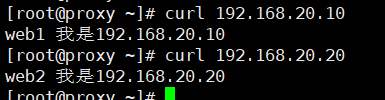
Step 3: client test
The client uses the curl command to test repeatedly to see whether the visited page will poll different back-end real servers

Because the weight of web2 is 2, the test results are as follows
Extended knowledge: the default LVS does not have the health check function. You need to manually write the dynamic detection script to realize this function
Reference script
vim check.sh
#! /bin/bash
VIP=192.168.4.15:80
RIP1=192.168.4.100
RIP2=192.168.4.200
while:
do
        for IP in $RIP1 $RIP2
        do
                curl -s http://$IP &> /dev/null
                if [ $? -eq 0 ];then
                        ipvsadm -Ln | grep -q $IP || ipvsadm -a -t $VIP -r $IP
                else
                        ipvsadm -Ln | grep -q $IP && ipvsadm -d -t $VIP -r $IP
                fi
        done
        sleep 1
done