Bisher - acoustooptic electronic organ based on single chip microcomputer
Note: this resource can be obtained in WeChat official account: Kevin learning station.
1, Work display
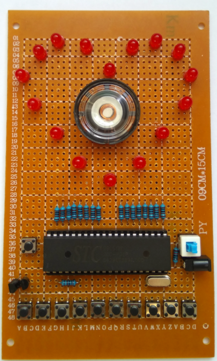
1.1. Physical drawing of works
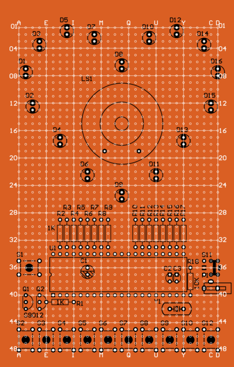
1.2 welding layout
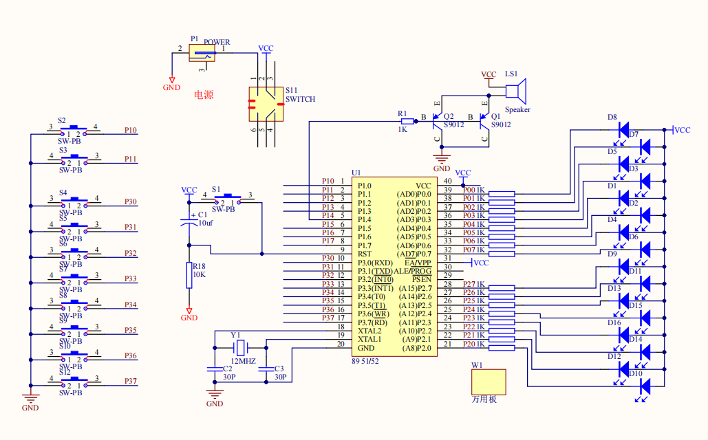
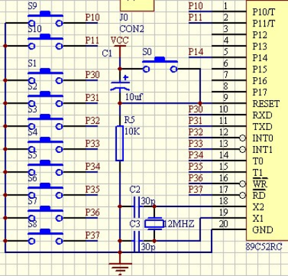
1.3 PCB schematic diagram
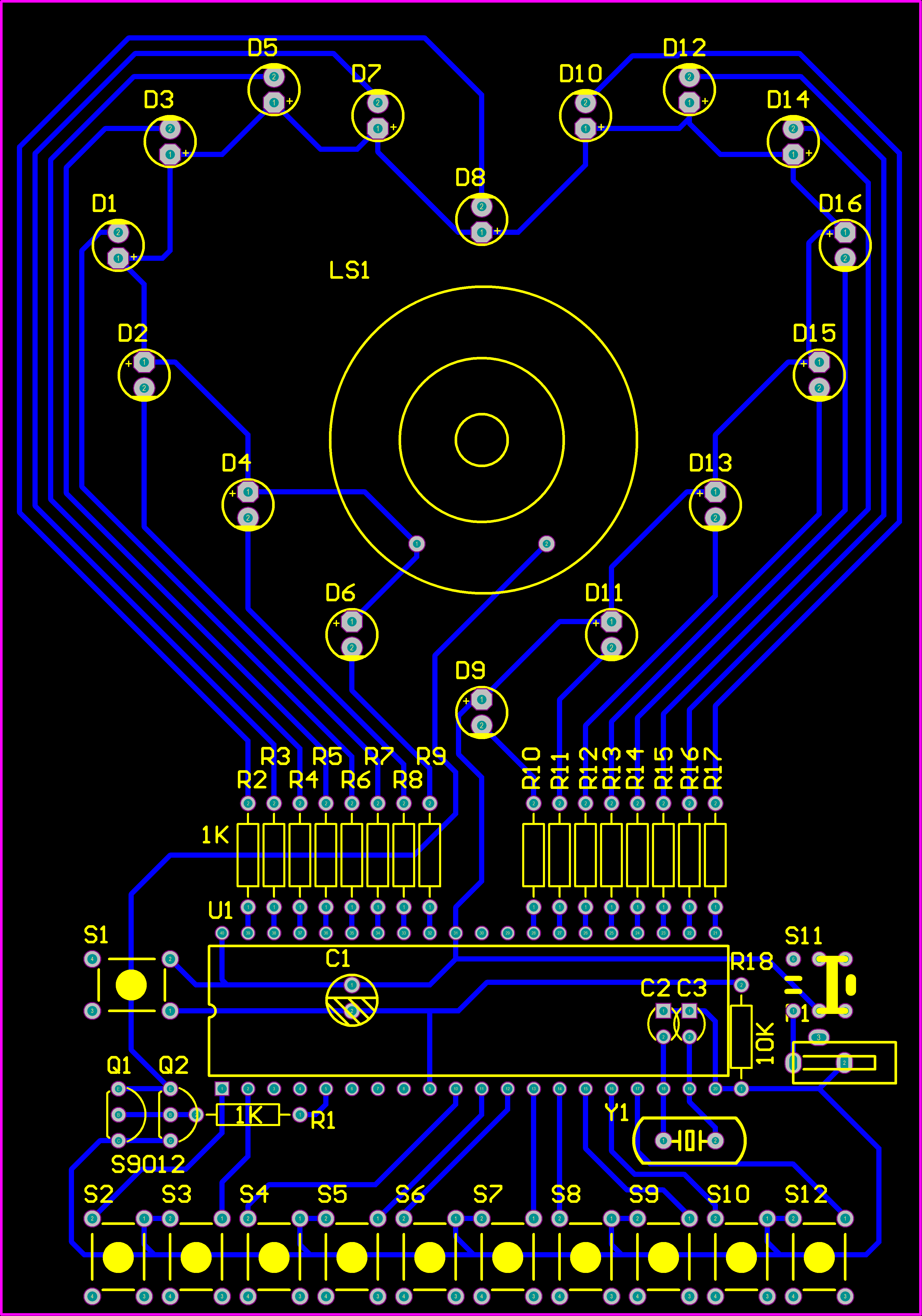
1.4 PCB diagram
2, Design process
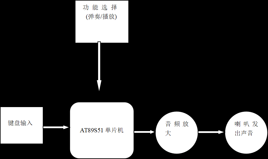
2.1 basic design idea of the system
This design is to display the change of light on the LED light, and the loudspeaker plays the music. The circuit includes: keyboard, MCU and LED display circuit, sound circuit.
2.1.1 description of each part
(1) The keyboard is used to play music with eight keys and eight notes.
(2) The single chip microcomputer drives and controls each part to work normally by outputting various electric pulse signals.
(3) The signals sent by the single chip microcomputer are decoded by the LED display circuit, and finally displayed by the speaker in the LED small lamp and sound circuit.
2.1.2 the system has worked too hard
To generate audio pulse, the main processing process is completed in the CPU. The CPU will read the data of the note input signal at any time. After reading the value of the corresponding register, the CPU processes the read value, and then plays the music through the speaker through the I/O port.
2.2 demonstration of unit circuit scheme
According to the design requirements, the system is mainly composed of controller module, display module and input module. In order to better realize the functions of each module, we have designed the following schemes and demonstrated them respectively.
2.2.1 controller module
Scheme 1: Lingyang series single chip microcomputer is used as the controller of the system
Sunplus series single chip microcomputer can realize various complex logic functions, with large module and high density. It integrates all devices on one chip, reduces the volume and improves the stability. Sunplus series single chip microcomputer improves the processing speed of the system and is suitable for being the control core of large-scale real-time system.
Scheme 2: 51 series is used as the system controller
Single chip microcomputer has strong arithmetic operation function, flexible software programming and large degree of freedom. Various algorithms and logic control can be realized by software programming. Because of its low power consumption, small size, mature technology and low cost, it is widely used in various fields. And good anti-interference performance.
Because the price of 51 single chip microcomputer is much lower than that of Lingyang series, and this design does not need high processing speed, from the perspective of economy and convenient use, scheme 2 is selected in this design.
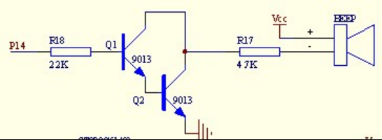
2.2.2 sounding module
The sound module is the most important part of this design.
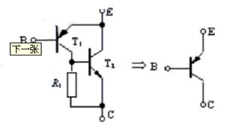
Basic scheme: the generation circuit is the most important part of the design circuit. It plays an important role in amplifying and outputting the sound signal generated by the single chip microcomputer. The sound generation circuit in my design is mainly composed of two CS9013. CS9013 is a low-power amplifier tube, which belongs to NPN triode. The following methods are used to judge the triode pin.
1. Judge the base of triode. For NPN triode, connect the black probe to one electrode and the red probe to the other two electrodes respectively. If the measured resistance values are both small and the measured resistance values are both large after changing the probe, it can be judged that the black probe is connected to the base electrode in the first measurement; If the measured values vary greatly from large to small, the black probe is not connected to the base electrode in the first measurement, and other electrodes should be replaced for retest.
2. Measure emitter E and collector c of triode. After the base of the triode is determined, measure the resistance between E and c poles twice by exchanging the probes. If the two measurement results are not equal, the one with the smaller resistance is e pole with the red probe and the black probe is c pole. For the PNP type triode, the method is similar to that of NPN, except that the red and black probes have the opposite effect. When measuring the resistance between E and c poles, it should be noted that the V (BR) CEO of the triode is very small, so it is easy to breakdown the emitter junction.
When the pin judgment of our triode is finished, we can use two triodes to form a Darlington structure. First of all, when the P1.0 port of the single chip microcomputer outputs a high level, the Darlington composed of two triodes can be turned on, which can amplify the current to a certain extent. In this way, when the signal is transmitted to the speaker, we can listen more clearly.
2.2.3 programming software module
Scheme 1: programming with assembly language
Assembly language instructions are expressed by some memory aids with corresponding meanings. Therefore, it is easier to master and use than machine language, but on the other hand, it directly uses CPU resources, which is difficult to master compared with high-level programming language.
Scheme 2: C language programming
Compared with other high-level languages, C language has the main characteristics of richness of operators, flexibility of syntax expression, compatibility with software and hardware operation, novelty of input and output mode and so on In depth analysis and study of these characteristics can deepen the understanding of C language; These features can be applied flexibly and effectively to solve various problems
Because I didn't have a deep understanding of assembly language in college, and I always used C language in programming, so I chose scheme 2.
2.2.4 final scheme
After repeated demonstration, the following scheme is finally determined:
(1) STC89C51 single chip microcomputer is used as the main controller.
(2) The Darlington effect is used to amplify the music signal
(3) Programming with C language
2.3 single chip microcomputer AT89C51
AT89S51 is a low-power, high-performance CMOS 8-bit single chip microcomputer with 4K bytes ISP (in system programmable) Flash read-only program memory that can be rewritten 1000 times. The device is manufactured by ATMEL's high-density and nonvolatile storage technology and is compatible with the standard MCS-51 instruction system and 80C51 pin structure, The chip integrates a general 8-bit CPU and ISP Flash storage unit. The powerful microcomputer AT89S51 can provide cost-effective solutions for many embedded control application systems.
AT89S51 has the following features: 40 pins, 4k Bytes Flash on-chip program memory, 128 bytes random access data memory (RAM), 32 external bidirectional input / output (I/O) ports, 5 interrupt priority, 2-layer interrupt nested interrupts, 2 16 bit programmable timing counters, 2 full duplex serial communication ports, watchdog (WDT) circuit and on-chip clock oscillator. AT89S51 pin diagram
In addition, the AT89S51 is designed and configured with an oscillation frequency of 0Hz, and the power saving mode can be set by software. In the idle mode, the CPU stops working, while the ram timing counter, serial port and external interrupt system can continue to work. In the power down mode, the oscillator is frozen to save RAM data, and other functions of the chip are stopped until the external interrupt is activated or the hardware is reset. At the same time, the chip also has three packaging forms: PDIP, TQFP and PLCC to meet the needs of different products.
Main functional features:
·Compatible with MCS-51 instruction system · 4k rewritable (> 1000 times) ISP Flash ROM
·32 bidirectional I/O ports · 4.5-5.5V working voltage
·2 16 bit programmable timing / counter · clock frequency 0-33MHz
·Full duplex UART serial interrupt port line · 128x8bit internal RAM
·2 external interrupt sources · low power idle and power saving modes
·Interrupt wake-up power saving mode · Level 3 encryption bit
·Watchdog (WDT) circuit · software setting idle and power saving functions
·Flexible ISP byte and paging programming · dual data register pointer
STC89C51 is a low-voltage, high-performance COMOS 8-bit microprocessor with 8K byte programmable erasable read-only memory, commonly known as single chip microcomputer. The device is manufactured by ATMEL high-density nonvolatile memory manufacturing technology and is compatible with the industrial standard MCS-51 instruction set and output pin.
The pin diagram of single chip microcomputer is shown in the figure
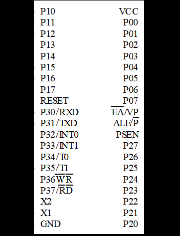
Fig. 1 pin diagram of STC89C51 single chip microcomputer
3, Hardware circuit design
3.1 minimum system design
The minimum system includes single chip microcomputer and its necessary power supply, clock, reset and other components, which can make the single chip microcomputer always in normal operation. Power supply, clock and other circuits are the necessary conditions for the operation of single chip microcomputer. The minimum system can be taken as the core part of the application system. Through memory expansion and A/D expansion, the single chip microcomputer can complete more complex functions.
3.2 clock circuit
STC89C51 has a high gain inverting amplifier used to form the oscillator. Pins RXD and TXD are the input and output of the amplifier respectively. The clock can be generated internally or externally. The internal clock will not be described in detail here. The clock circuit of external mode is shown in Figure 3. RXD is grounded and TXD is connected to external oscillator. There are no special requirements for external oscillation signals, only the pulse width is required to be guaranteed. Generally, square wave signals with a frequency of about 12MHz are used.
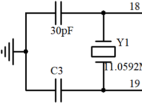
Figure 2 89c51 internal clock circuit
3.3 reset circuit
When a high level is introduced into the RST pin of 89C51 single chip microcomputer and maintained for 2 machine cycles, the single chip microcomputer will perform the reset operation (if the pin remains high, the single chip microcomputer will be in the cyclic reset state).
The reset circuit usually adopts power on automatic reset and button reset.
In the simplest power on automatic reset circuit, the power on automatic reset is realized through the capacitor charge and discharge of the external reset circuit. As long as the rising time of Vcc does not exceed 1ms, automatic power on reset can be realized.
In addition to power on reset, sometimes you need to press the key to reset manually. This design is to use the key to reset manually. There are two manual reset modes: level mode and pulse mode. The level reset is realized by connecting the RST (9) terminal with the power supply Vcc. The key manual reset circuit is shown in Figure 4. When the clock frequency is 11.0592MHZ, C is 10uF and R is 10k Ω.
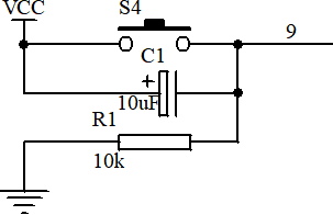
Figure 3 89C51 reset circuit
3.4 key control module
The electronic organ is equipped with 11 keys, of which 8 are used as note input. The 8 keys represent 8 notes respectively, including all notes of the midrange segment, which are designed by software and hardware. The other three are control reset, water lamp conversion and automatic music playback.
As shown below:
3.5 playback module
The playback module is composed of two triodes. The triode amplifies the signal and then transmits it to the horn. The horn has almost no noise and good sound effect.
The following figure shows the circuit of the module:
4, Procedure flow
4.1 procedure flow chart
The design scheme is to press the note to be expressed at will through the key, which is sent to the main circuit as the level. The central processor outputs the note through recognition and decoding, and sends out effective sound in the speaker. In this way, we can continuously play the notes or tones we want. The circuit is composed of reset circuit, indicator circuit and function key circuit. Through the function key, we can choose to play music or play syllables. The hardware is mainly composed of the following parts.
5, Program code
/*
8 Eight keys emit eight basic tones,
It can play built-in music, and the music flashes with the light
*/
#include<reg52.h>
#define uint unsigned int
#define uchar unsigned char
sbit speaker=P1^4;//Horn connected to 30 pins
sbit key1=P1^0;//Water light button (temporary)
sbit key2=P1^1;//Play music button (tentative)
uchar a,b,num1,s1num,n1,n2;
uchar qushu=0;
char num;//num can be defined as a negative number
uchar code yinfu[]={0xfb,0xe9,      //Do
                   0xfc,0x5c,      //Re
                   0xfc,0xc1,      //Mi
                   0xfc,0xef,      //Fa
                   0xfd,0x45,      //So
                   0xfd,0x92,      //La
                   0xfd,0xd0,      //Si
                   0xfd,0xee,      //Do#
				   0x00,0x00,	   //interval
};
uchar code shengri_tone[]={   1,0,1,2,1,4,3,0, //Happy birthday tone
                                   1,0,1,2,1,5,4,0,
                                   1,0,1,8,6,4,3,2,0,
                                   7,0,7,6,4,5,4,0       //0 means no sound, i.e. pause; Numbers are tones
};
uchar code laohu_tone[]={1,2,3,1,0,1,2,	//Two tigers score 40 notes
					3,1,0,3,4,5,0,3,
					4,5,0,5,6,5,4,3,
					1,0,5,6,5,4,3,1,
					0,3,2,1,0,3,2,1,0

};
uchar code yishan_tone[]={1,1,5,5,6,6,5,	//Star score 54 notes
						0,4,4,3,3,2,2,
						1,0,5,5,4,4,3,
						3,2,0,5,5,4,4,
						3,3,2,0,1,1,5,5,
						6,6,5,0,4,4,3,
						3,2,2,1,0
};
uchar code shengri_beat[]={   24,1,24,48,48,48,72,5,//rhythm
                                   24,1,24,48,48,48,72,5,
                                   24,1,24,48,48,48,48,72,5,
                                   24,1,24,48,48,48,72,5    //Beat, that is, the delay of each tone in tone meter
};
uchar code laohu_beat[]={   24,24,24,48,5,24,24,//rhythm
                                   24,48,5,24,24,48,5,24,
                                    24,72,5,24,24,24,24,//rhythm
                                   24,48,5,24,24,24,24,24,72,
								     5,24,24,48,5,24,24,//rhythm
                                   72,5//Beat / / beat, that is, the delay of each tone in the tone table
};
uchar code yishan_beat[]={   24,24,24,24,24,24,48,//rhythm
                                   5,24,24,24,24,24,24,72,
                                    5,24,24,24,24,24,24,//rhythm
                                   48,5,24,24,24,24,24,24,72,
								     5,24,24,24,24,24,24,//rhythm
                                   48,5,24,24,24,24,24,24,72,5//Beat, that is, the delay of each tone in tone meter
};
uchar code ledtable[]={0x7f,0xbf,0xdf,0xef, //Reverse
0xf7,0xfb,0xfd,0xfe};//LED code of P0 group port (welding process may be reversed, specific changes)
uchar code ledtable2[]={0x7f,0xbf,0xdf,0xef, //Reverse
0xf7,0xfb,0xfd,0xfe};//P2 group port LED code, opposite!
void check_key();//Change P3 group to key
void keyscan();
void turn();//Clockwise flow
void back();
void qianhou();
void dangshuang();
void delay(uint z);//Delay function declaration
void delay1(void);//Declare the second delay function
void play1(void);//Happy birthday

void main()
{
	s1num=0;//Water lamp type mark
	key1=1;
	key2=1;
	TMOD=0x01;
	TH0=a;
	TL0=b;
	ET0=1;//The timer is turned on, but interrupt is not allowed
	TR0=1;
	while(1)
	{
	check_key();
	keyscan();
	}
}

void time0() interrupt 1
{
	TH0=a;
	TL0=b;
	speaker=~speaker;
}
void check_key()
{
	P3=0xff;//First assign high level to P2 group port
	switch(P3)//Press a key and the corresponding four lights are on
	{
		case 0xfe:P0=0xee;P2=0x77;a=0xfb;b=0xe9;EA=1;break;//Groups P0 and P2 are led groups
		case 0xfd:P0=0xdd;P2=0xbb;a=0xfc;b=0x5c;EA=1;break;//Note: EA cannot be changed to TR0
		case 0xfb:P0=0xbb;P2=0xdd;a=0xfc;b=0xc1;EA=1;break;
		case 0xf7:P0=0x77;P2=0xee;a=0xfc;b=0xef;EA=1;break;
		case 0xef:P0=0xee;P2=0x77;a=0xfd;b=0x45;EA=1;break;
		case 0xdf:P0=0xdd;P2=0xbb;a=0xfd;b=0x92;EA=1;break;
		case 0xbf:P0=0xbb;P2=0xdd;a=0xfd;b=0xd0;EA=1;break;
		case 0x7f:P0=0x77;P2=0xee;a=0xfd;b=0xee;EA=1;break;
		default:EA=0;speaker=0;//P0=0xff;P2=0xff ;
	}
}
void delay(uint z)
{
	uint x,y;
	for(x=z;x>0;x--)
	for(y=110;y>0;y--);
}
void keyscan()
{
	  if(key1==0)
	  {
	  	delay(5);
		if(key1==0)
		{
			s1num++;
			while(!key1);
			if(s1num==1)
			{
				turn();
			}
		}
		if(s1num==2)
		{
			back();
		}
		if(s1num==3)
		{
			qianhou();
		}
		if(s1num==4)
		{
			dangshuang();
		}
		if(s1num==5)
			s1num=1;
	  }
		if(key2==0)
		{
			delay(5);
			if(key2==0)
			{
			  	 qushu++;
				 if(qushu==4)
				{
				 	qushu=1;
			    }
				 while(~key2);
				 play1();
			}

		}
}

 void delay1(void)//Second delay function
{
       uchar n=15;
       while(n--)
       {
              uchar i;
              for(i=0;i<125;i++);
       }
}
void play1(void)//Happy birthday
{

       uchar m=0;
       uchar s;
       uchar c=1;
	   P0=0xaa;
	   P2=0x55;
	   if(qushu==1)
	   {
	       while(1)
	       {
	              EA=0;
	              c=shengri_tone[m];                            //Take notes
	              s=shengri_beat[m];                      //Take the beat
	              a=yinfu[2*c-2];
	              b=yinfu[2*c-1];
	              EA=1;
	              while(s--)
	              {
	                     delay1();
						 P0=~P0;
						 P2=~P2;
	              }
	              m++;
	              if(m>=33) return;                      //The value is the number of elements in the shengri correlation table
	       }
	  }
	  else if(qushu==2)
	  {
	  	 while(1)
	       {
	              EA=0;
	              c=laohu_tone[m];                            //Take notes
	              s=laohu_beat[m];                      //Take the beat
	              a=yinfu[2*c-2];
	              b=yinfu[2*c-1];
	              EA=1;
	              while(s--)
	              {
	                     delay1();
						 P0=~P0;
						 P2=~P2;
	              }
	              m++;
	              if(m>=40) return;                      //shengri is the number of related elements in the table
	       }
	  }
	  	  else if(qushu==3)
	  {
	  	 while(1)
	       {
	              EA=0;
	              c=yishan_tone[m];                            //Take notes
	              s=yishan_beat[m];                      //Take the beat
	              a=yinfu[2*c-2];
	              b=yinfu[2*c-1];
	              EA=1;
	              while(s--)
	              {
	                     delay1();
						 P0=~P0;
						 P2=~P2;
	              }
	              m++;
	              if(m>=48) return;                      //The value is the number of elements in the shengri correlation table
	       }
	  }
}


/*The following are N flow patterns of water lamps*/
void turn()//The running water lamp moves clockwise (5 times)
{

	 for(num1=0;num1<8;num1++)
	 {
	 for(num=0;num<8;num++)
	 {
	 	  P0=ledtable[num];
		  delay(30);//Tentative time
	 }
	 P0=0xff;//Then close P1 group
	 for(num=7;num>-1;num--)
	 {
	 	P2=ledtable2[num];
		delay(30);
	 }
	 P2=0xff;//Then close the P2 group
	 }
}
void back()//Counterclockwise flow
{
	for(num1=0;num1<8;num1++)
	{
	for(num=0;num<8;num++)
	{
		P2=ledtable[num];
		delay(30);
	}
	P2=0xff;
	for(num=7;num>-1;num--)
	{
		P0=ledtable2[num];
		delay(30);
	}
	P0=0xff;
	}
}
void qianhou()//Back and forth
{
	for(num1=0;num1<10;num1++)
	{
	for(num=0;num<8;num++)
	{
		P0=ledtable[num];
		P2=ledtable2[num];
		delay(30);
	}
	P0=0xff;
	P2=0xff;
	for(num=7;num>-1;num--)
	{
		P0=ledtable[num];
		P2=ledtable2[num];
		delay(30);
	}
	P0=0xff;
	P2=0xff;
	}
}
void dangshuang()//Odd even
{
	for(num1=0;num1<15;num1++)
	{
	 P0=0x55;
	 P2=0xaa;
	 delay(150);
	 P0=0xaa;
	 P2=0x55;
	 delay(150);
	 }
}
6, Resource acquisition
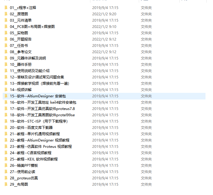
The project simulation and PCB project have been placed in the official account below, and can be concerned about the official account: Kevin learning station, and input key words: "acoustic and electronic organ", which can be obtained free of charge. It's not easy to create, but your praise, attention and collection are my greatest encouragement!