1, Working principle of LVS-DR
1. Packet flow analysis
(1) The client sends a request to the director server (load balancer), and the requested data message (the source IP is CIP and the target IP is VIP) reaches the kernel space.
(2) The director server and Real Server are in the same network, and the data is transmitted through the two-layer data link layer.
(3) The kernel space judges that the target IP of the packet is the local VIP. At this time, IPVS(IP virtual server) compares whether the service requested by the packet is a cluster service. If it is a cluster service, the packet is re encapsulated. Modify the source MAC address to the MAC address of Director Server and the target MAC address to the MAC address of Real Server. The source IP address and the target IP address have not changed, and then send the packet to Real Server.
(4) If the MAC address of the request message arriving at the Real Server is its own MAC address, this message will be received. The data packet re encapsulates the message (the source IP address is VIP and the target IP is CIP), transmits the response message to the physical network card through the lo interface, and then sends it out.
(5) The real server directly transmits the response message to the client.
2. Characteristics of Dr mode
(1) Director Server and Real Server must be in the same -- physical network.
(2)RealServer can use either a private address or a public address. If the public network address is used, RIP can be accessed directly through the Internet.
(3) The director server acts as an access portal to the cluster, but not as a gateway.
(4) All request messages pass through the Director Server, but the reply response message cannot pass through the Director Server.
(5) The gateway of the Real Server is not allowed to point to the Director Server IP, that is, the packets sent by the Real Server are not allowed to pass through the Director Server.
(6) The lo interface on the real server configures the IP address of the VIP.
3. ARP problem in LVS Dr
1.ARP request
ARP is an address resolution protocol, which realizes to know its physical address through IP address. For example, if host A wants to send data to host B, it first needs to look up the ARP table and find the MAC address of mapping host B Knowing the MAC address of host B, you can write the target MAC address into the frame and send it
If the target IP address is not found in the ARP cache table, host A will send A broadcast on the network, inform all hosts in the LAN of their own IP address and MAC address, and ask what the MAC address of host B is?
Other hosts on the network do not respond to ARP queries. Host B only responds to host A when it receives this frame
In this way, host A knows the MAC address of host B and can send information to host B At the same time, A and B also update their ARP cache table (because A tells B their IP and MAC addresses when asking)
The next time A sends information to host B or B sends information to A, just look it up directly from their ARP cache table
2. DR model of LVS
In the DR model of LVS, the scheduler and all Real Server are configured with VIP and are all in the same network segment. To ensure that the arp broadcast request of the client is only responded by the scheduler, the Real Server request gateway MAC address needs to use the local IP address without using the VIP address. You must change the arp default response rule of real server, which is to modify the kernel parameter arp_ignore
arp_ignore
Function: control whether the system returns arp response message when receiving arp broadcast request message
Common value interpretation
0. If any network card interface on the host has the IP address in the arp broadcast request message, it will respond
1. Only respond to arp requests whose destination IP address is the local address on the receiving network card
2. Only respond to arp requests whose destination IP address is the local address on the receiving network card, and the source IP of the arp request must be in the same network segment as the receiving network card
2, LVS-DR deployment process
DR The server: 192.168.10.11
Web Server 1:192.168.10.12
Web Server 2:192.168.10.13
 Shared server: 192.168.10.14
vip: 192.168.10.100
 client: 12.0.0.12
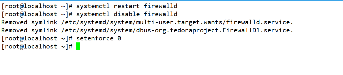
1. Configure load scheduler (192.168.10.14)
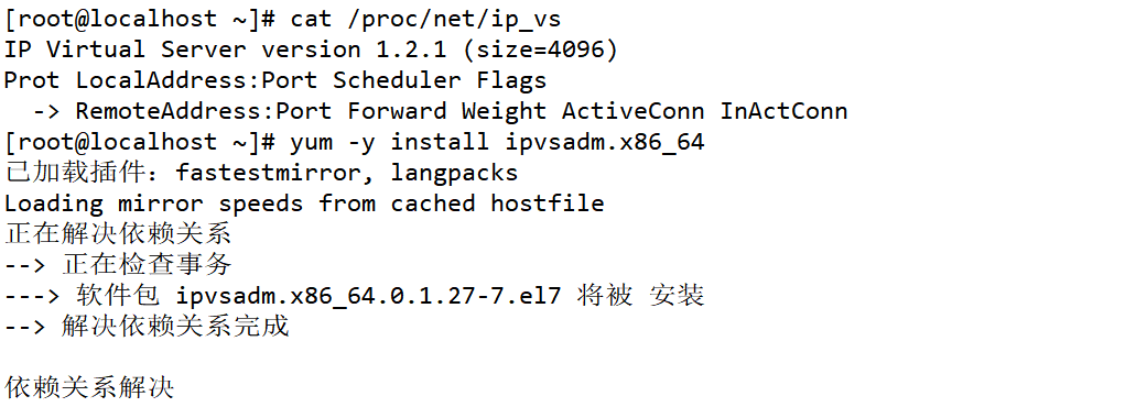
systemctl stop firewalld.service
setenforce 0
modprobe ip_vs
cat /proc/net/ip_vs
yum -y install ipvsadm
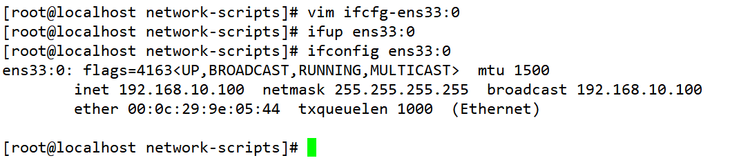
1) Configure virtual IP address (VIP: 192.168.10.100)
cd /etc/sysconfig/network-scripts/
cp ifcfg-ens33 ifcfg-ens33:0           #If tunnel mode, copy to ifcfg-tunl0
vim ifcfg-ens33:0
DEVICE=ens33:0
ONBOOT=yes
IPADDR=192.168.10.100
NETMASK=255.255.255.255
ifup ens33:0

2) adjust proc response parameters
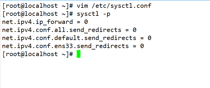
Since the LVS load scheduler and all nodes need to share VIP addresses, the redirection of icmp needs to be turned off and does not act as a router.
vim /etc/sysctl.conf
net.ipv4.ip_forward = 0
net.ipv4.conf.all.send_redirects = 0
net.ipv4.conf.default.send_redirects = 0
net.ipv4.conf.ens33.send_redirects = 0
sysctl -p

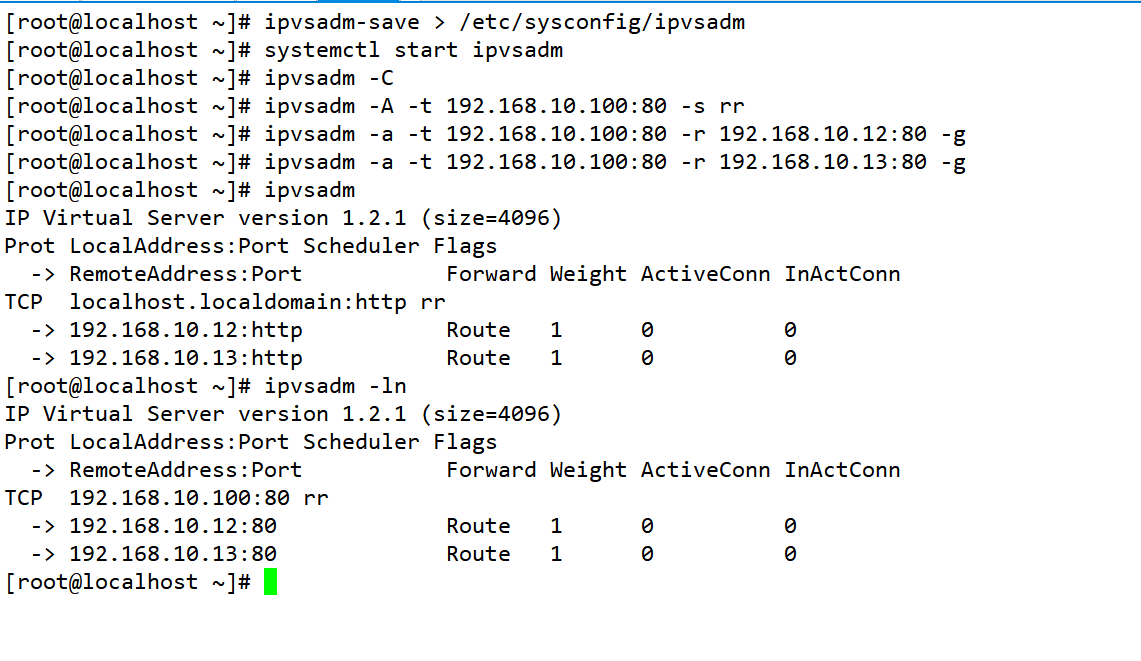
3) configure load distribution strategy
ipvsadm-save > /etc/sysconfig/ipvsadm
systemctl start ipvsadm
ipvsadm -C
ipvsadm -A -t 192.168.10.100:80 -s rr
ipvsadm -a -t 192.168.10.100:80 -r 192.168.10.20:80 -g  #If tunnel mode, - g is replaced by - i
ipvsadm -a -t 192.168.10.100:80 -r 192.168.10.30:80 -g
ipvsadm
ipvsadm -ln                                             #View the node status. Route represents DR mode
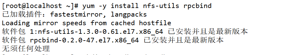
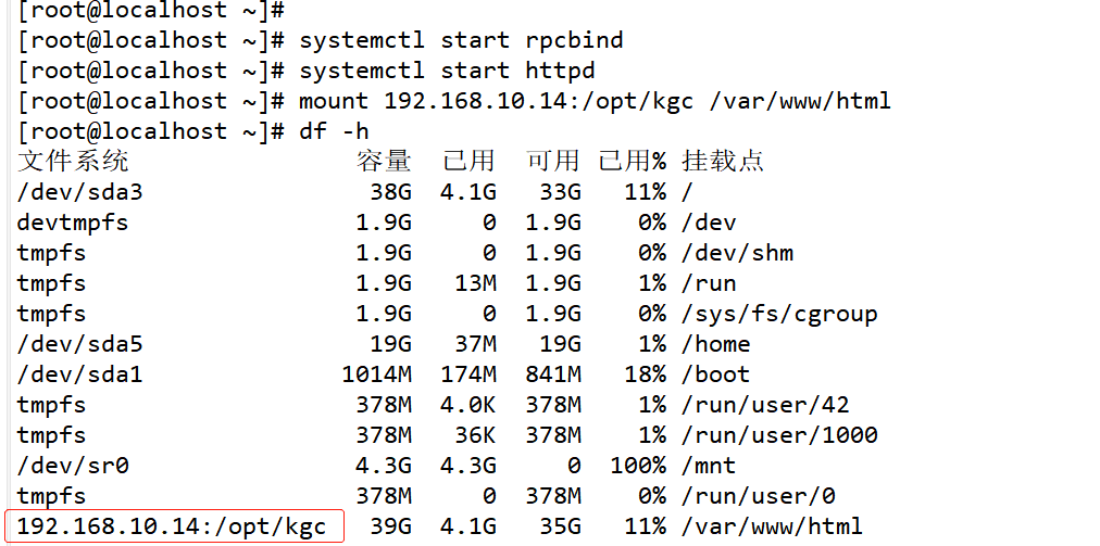
2. Deploy shared storage (NFS server: 192.168.10.14)
systemctl stop firewalld.service
setenforce 0
yum -y install nfs-utils rpcbind

mkdir /opt/kgc /opt/benet
chmod 777 /opt/kgc /opt/benet

vim /etc/exports
/opt/kgc 192.168.10.0/24(rw,sync)
/opt/benet 192.168.10.0/24(rw,sync)

systemctl start rpcbind.service
systemctl start nfs.service

echo 'this is kgc web! ' > /opt/kgc/index.html
echo 'this is benet web! ' > /opt/benet/index.html


3. Configure node server (192. 168.10.12, 192. 168.10.13)
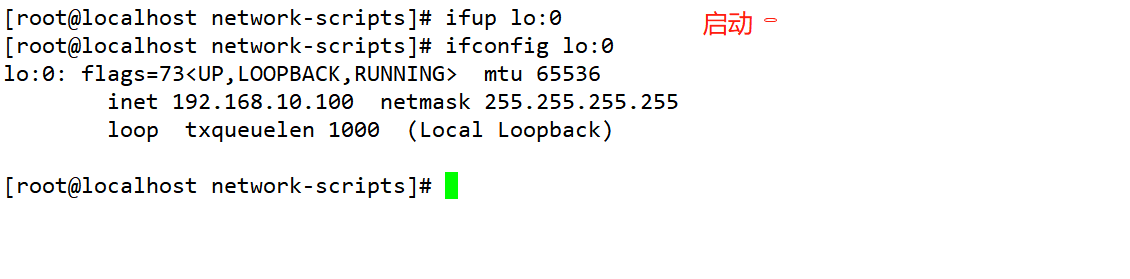
1) Configure virtual IP address (VIP:192.168.80.100)
This address is only used as the source address for sending Web response packets, and does not need to listen to the client's access requests (instead, the scheduler listens and distributes them). Therefore, the virtual interface lo:0 is used to host the VIP address, and a routing record is added for the local machine to limit the data accessing the VIP locally to avoid communication disorder
cd /etc/sysconfig/network-scripts/
cp ifcfg-lo ifcfg-lo:0

vim ifcfg-lo:0
DEVICE=lo:0
ONBOOT=yes
IPADDR=192.168.10.100
NETMASK=255.255.255.255                   #Note: the subnet mask must be all 1

ifup lo:0
ifconfig lo:0
route add -host 192.168.10.100 dev lo:0
vim /etc/rc.local
/sbin/route add -host 192.168.10.100 dev lo:0
chmod +x /etc/rc.d/rc.local


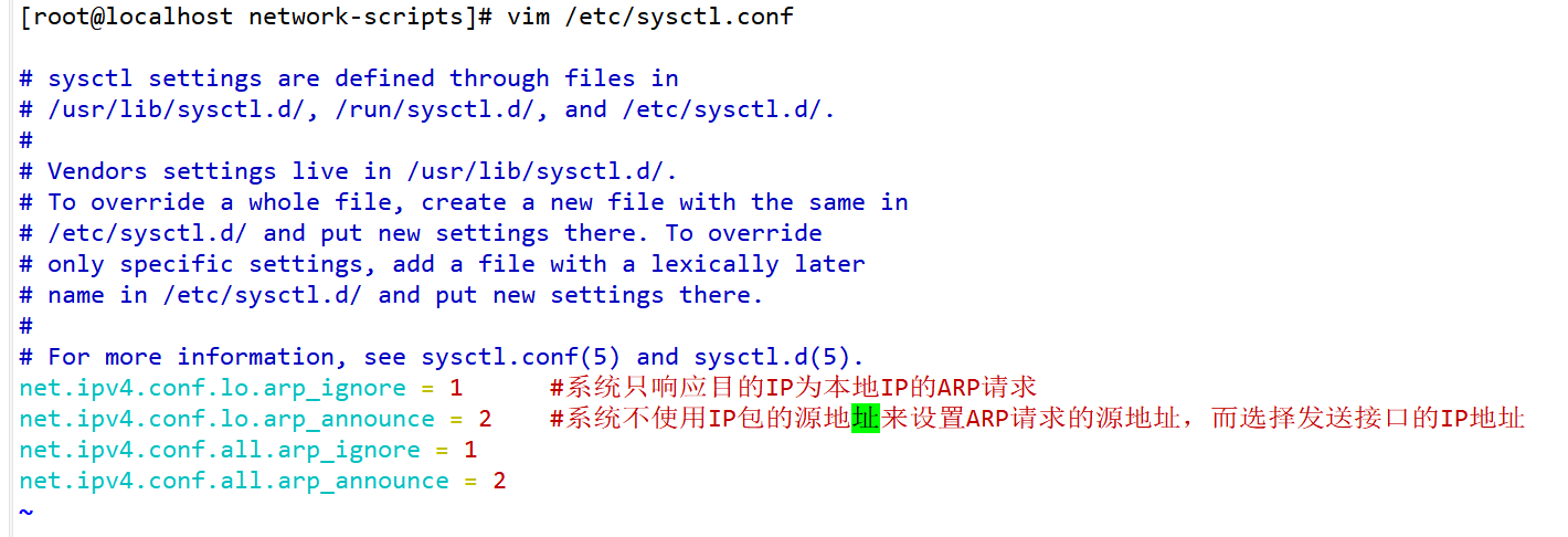
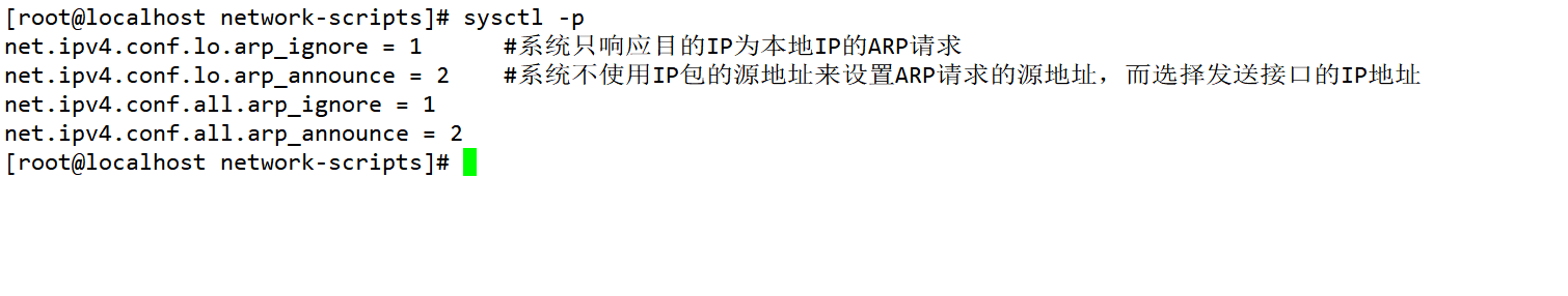
2) adjust the ARP response parameters of the kernel to prevent updating the MAC address of VIP and avoid conflict
vim /etc/sysctl.conf
net.ipv4.conf.lo.arp_ignore = 1      #The system only responds to ARP requests whose destination IP is local IP
net.ipv4.conf.lo.arp_announce = 2    #The system does not use the source address of the IP packet to set the source address of the ARP request, but selects the IP address of the sending interface
net.ipv4.conf.all.arp_ignore = 1
net.ipv4.conf.all.arp_announce = 2
sysctl -p

or

echo "1" > /proc/sys/net/ipv4/conf/lo/arp_ignore
echo "2" > /proc/sys/net/ipv4/conf/ lo/arp_announce
echo "1" > /proc/sys/net/ipv4/conf/all/arp_ignore
echo "2" > /proc/sys/net/ipv4/ conf/all/arp_announce
sysctl -p
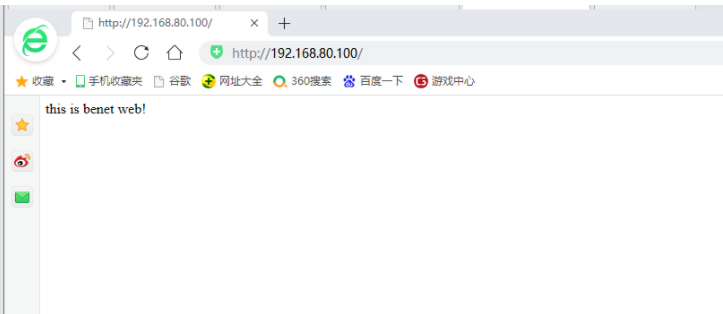
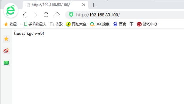
4. Test LVS Cluster
Use browser access on the client http://192.168.80.100/
summary
Three working modes of LVS, briefly describe their differences?
NAT: a virtual server implemented through network address translation. In case of large concurrent access, the performance of the scheduler becomes a bottleneck
DR: use routing technology to realize virtual server. Node server needs to be configured with VIP. Pay attention to MAC address broadcast
TUN: realize virtual server through tunnel.