catalogue
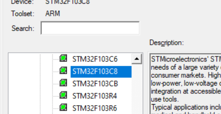
1. Open keil5 to create a project selection chip (stm32F103c8 I use here)
5. Compile and generate hex file
2. Start the burning procedure
1, Experimental preparation
Install the following software on the computer in advance: keil5, mcuisp and CH340 driver
The installation process can be Baidu search, which is very simple. I won't repeat it here
Hardware requirements: STM32F103C8T6 board, several jumpers (supplied when buying the board), LED lights (cheap)
2, Find address
This step is difficult for beginners. You can refer to the following great God's blog
Then check the manual and learn the method (it's easy to persuade you to retreat)
3, Programming
1. Open keil5 to create a project selection chip (stm32F103c8 I use here)
2. Set chip parameters
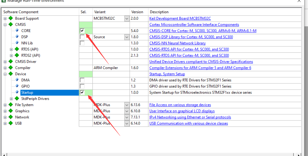
3. Add function file
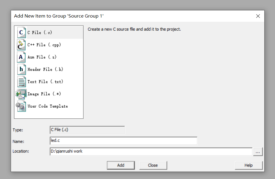
4. Write code
#define RCC_AP2ENR	*((unsigned volatile int*)0x40021018)
	//----------------GPIOA configuration register------------------------
#define GPIOA_CRH	*((unsigned volatile int*)0x40010804)
#define	GPIOA_ORD	*((unsigned volatile int*)0x4001080C)
//----------------GPIOB configuration register------------------------
#define GPIOB_CRL	*((unsigned volatile int*)0x40010C00)
#define	GPIOB_ORD	*((unsigned volatile int*)0x40010C0C)
//----------------GPIOC configuration register------------------------
#define GPIOC_CRH	*((unsigned volatile int*)0x40011004)
#define	GPIOC_ORD	*((unsigned volatile int*)0x4001100C)
//-------------------Simple delay function-----------------------
void  Delay_ms( volatile  unsigned  int  t)
{
     unsigned  int  i;
     while(t--)
         for (i=0;i<800;i++);
}
//------------------------Main function--------------------------
int main()
{
	int j=100;
	RCC_AP2ENR|=1<<2;			//APB2-GPIOA peripheral clock enable
	RCC_AP2ENR|=1<<3;			//APB2-GPIOB peripheral clock enable
	RCC_AP2ENR|=1<<4;			//APB2-GPIOC peripheral clock enable
	//These two lines of code can be combined into RCC_ APB2ENR|=1<<3|1<<4;
	GPIOA_CRH&=0xFFF0FFFF;		//Set bit reset
	GPIOA_CRH|=0x00020000;		//PA12 push pull output
	GPIOA_ORD|=1<<12;			//Set the initial light to on

	GPIOB_CRL&=0xFFFFFF0F;		//Set bit reset
	GPIOB_CRL|=0x00000020;		//PB1 push pull output
	GPIOB_ORD|=1<<1;			//Set the initial light to off

	GPIOC_CRH&=0xF0FFFFFF;		//Set bit reset
	GPIOC_CRH|=0x02000000;   	//PC14 push pull output
	GPIOC_ORD|=1<<14;			//Set the initial light to off
	while(j)
	{
		GPIOA_ORD=0x1<<12;		//PA12 high level
		Delay_ms(3000000);
		GPIOA_ORD=0x0<<12;		//PA12 low level
		Delay_ms(3000000);

		GPIOB_ORD=0x1<<1;		//PB1 high level
		Delay_ms(3000000);
		GPIOB_ORD=0x0<<1;		//PB1 low level
		Delay_ms(3000000);

		GPIOC_ORD=0x1<<14;		//PC14 high level
		Delay_ms(3000000);
		GPIOC_ORD=0x0<<14;		//PC14 low level
		Delay_ms(3000000);
	}
}
5. Compile and generate hex file
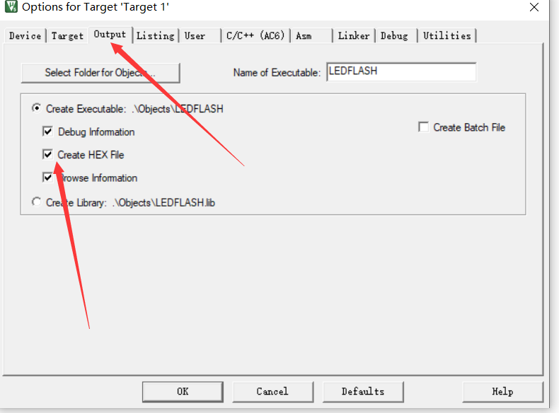
build, you can find the hex file in the file
4, Burning and achievements
1. Connection
Refer to this link and write it in detail
STM32 minimum core board F103 serial communication USART_ vic_ to_ CSDN blog
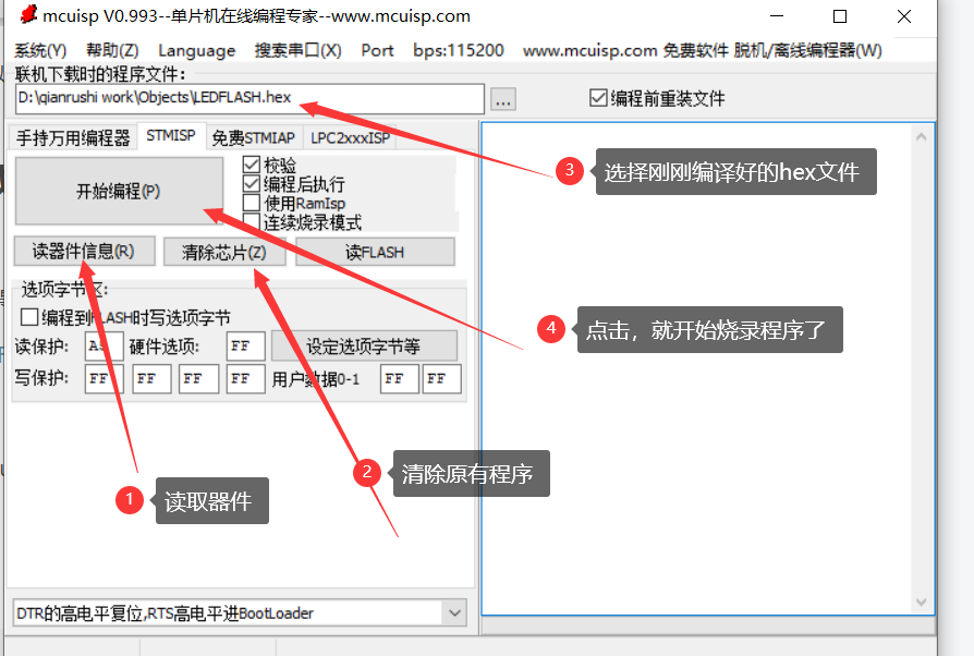
2. Start the burning procedure
Connect the board, open mcuisp and follow the steps shown in the figure
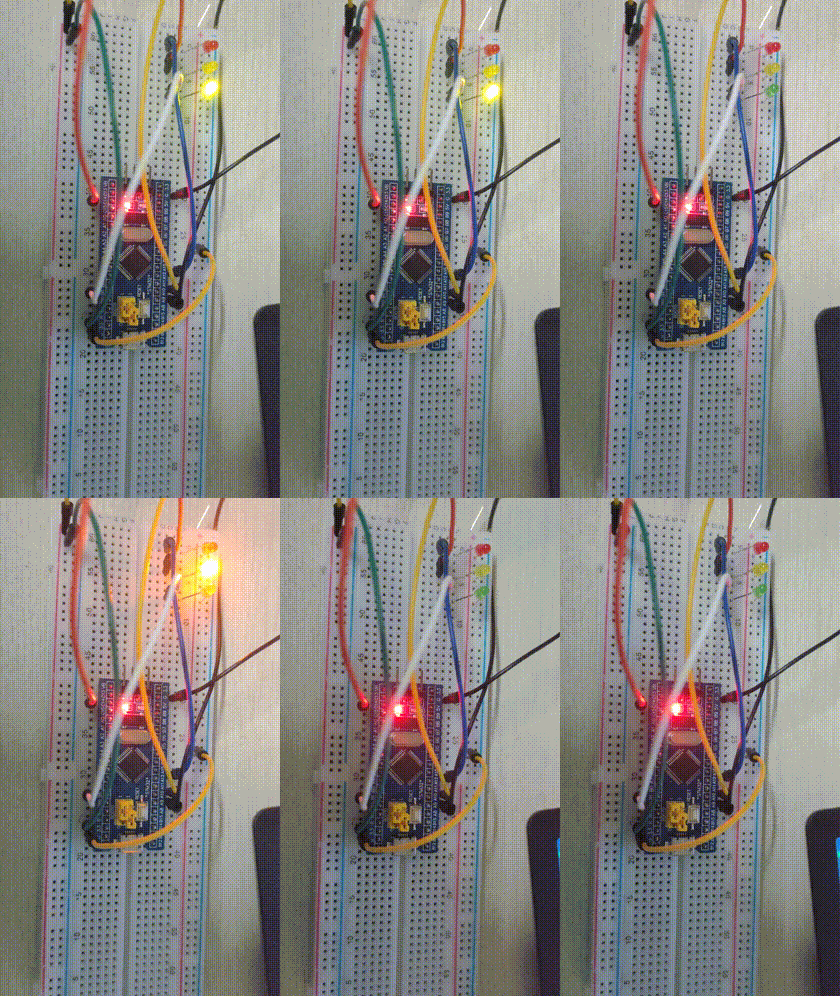
3. Effect display
5, Summary
This operation has deepened my understanding of the basis of single chip microcomputer. It seems to be some very simple things from learning to find the pin address to setting the clock and writing the code, but the operation is very time-consuming. However, this is the most original use method, which can deepen my understanding of the principle of single chip microcomputer and is very helpful for the use and learning of follow-up single chip microcomputer. I hope you can do a good job from the foundation, and the road will be more solid and steady in the future.
6, Reference
(7 messages) STM32 minimum core board F103 serial communication USART_ vic_ to_ CSDN blog