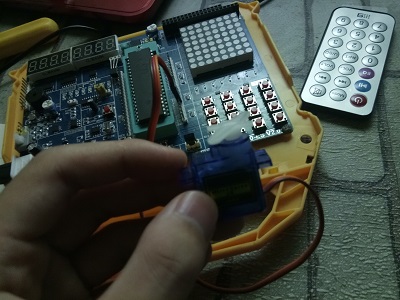
Preface
I don't know what to say. I bought STM32, and opencv is finally useful.
PPM and PWM
For example, to modulate the length of ton {on} ton, keep the tofft {off} toff unchanged.
PWM, pulse width modulation. For example, the modulation duty cycle is t on t \ frac {t {on} {t} {tton}, but the period is not changed.
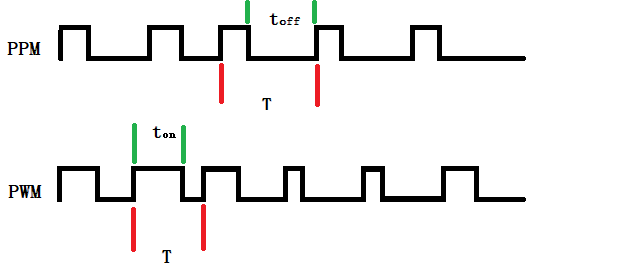
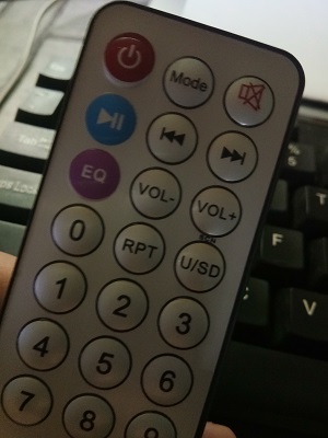
The remote control on my single chip computer sends data in the form of PPM code. 0 and 1 are defined by different length of ton {on} ton
Data format of infrared transmission
After receiving the 32-bit data, use the data inverse code and data code comparison as a measure to check whether there is any error.
It can be seen that the control of period and start code is more troublesome.
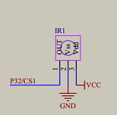
Infrared remote control schematic diagram
The transmitter sends the pulse signal and turns it into a digital signal when it reaches the receiver.
Infrared receiving module
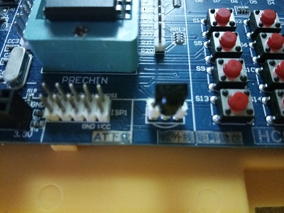
Sending module
External interrupt by infrared receiving
According to the schematic diagram, the output terminal of the receiving module is the external interrupt INT0 port. So we can write the code of receiving content in the function of external interrupt.
#include"reg52.h"

sbit LSA=P2^2;
sbit LSB=P2^3;
sbit LSC=P2^4;

sbit IR_IN=P3^2;//INT0
unsigned char IR_Receive[6];
unsigned char time;
unsigned char leds[3];
unsigned char code table[]={
	0x3f,0x06,0x5b,0x4f,0x66, //01234
	0x6d,0x7d,0x07,	0x7f,0x6f,//56789
	0x77,0x7c,0x39,0x5e,0x79, //abcde
	0x71,0X76 //fh
};

void delay(unsigned int i);
void show();
void IR_Init();
void main(){
	IR_Init();
	while(1)show();
}

void delay(unsigned int i){
	while(i--);
}

void show(){
	unsigned int j;
	leds[0]=table[16];///h
	leds[1]=table[IR_Receive[2]%16];
	leds[2]=table[IR_Receive[2]/16];
	for(j=0;j<3;j++){
		switch(j){
			case 0:
			LSC=0,LSB=0,LSA=0;
			break;
			case 1:
			LSC=0,LSB=0,LSA=1;
			break;
			case 2:
			LSC=0,LSB=1,LSA=0;
			break;
		}

		P0=leds[j];
		delay(100);
		P0=0;
	}

}
void IR_Init(){

	TCON=0x01;//IT0=1
	IE=0x81;//EA=1,EX0=1
	IR_IN=1;//initialize the port
}

void IR_Read()interrupt 0{
	unsigned char i,j;
	unsigned int error;


	delay(700);//~7ms
	if(IR_IN==0){
		error=1000;
		while(IR_IN==0&&error>0){ //~9ms
			delay(1);//~10us
			error--;
		}

		if(IR_IN==1){
			error=500;
			while(IR_IN==1&&error>0){ //~4.5ms
				delay(1);
				error--;
			}

			//4X8=32-bit data user code 16 bits, data code 8 bits, anti data code 8 bits
			for(i=0;i<4;i++){
				for(j=0;j<8;j++){
					time=0;

					error=60;
					while(IR_IN==0&&error>0){//~560us
						delay(1);
						error--;
					}

					error=500;
					while(IR_IN==1&&error>0){ //Calculate the time length of high level
						delay(10);//~100us
						error--;
						if(++time>30)return;
					}

					//Data transfer from low order
					IR_Receive[i]>>=1;
					if(time>=8)
						IR_Receive[i]|=0x80;


				}
			}

		}

		//Compare data code with data inverse code
		if(IR_Receive[2]!=~IR_Receive[3])
			return;//error
	}

}
After the display, we understand the coding of 21 keys on the remote control as follows.
45H(switch)       46H(Mode)          47H(Voice switch)
44H(play)       40H(Back off)           43H(Forward)
07H(EQ)			15H(VOL-)			09H(VOL+)
16H(0)			19H(RPT)            0DH(U/SD)
0CH(1)			18H(2)              5EH(3)
08H(4)          1CH(5)              5AH(6)
42H(7)          52H(8)              4AH(9)
Steering gear rotation
The steering gear is controlled by PWM, so you need to change ton {on} ton.
