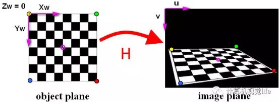
Binocular vision is based on geometric mathematics, and mathematical derivation is boring. Therefore, I will not introduce the mathematical principles here, but briefly describe the process of binocular vision.
Binocular vision mainly includes five parts: camera calibration, image distortion correction, camera correction, image matching and 3D restoration.
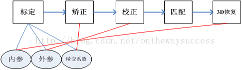
Let's start with camera calibration. Camera calibration has two purposes.
- First, to restore the position of the object imaged by the camera in the real world, we need to know how the object in the world transforms into the computer image plane. One of the purposes of camera calibration is to find out this transformation relationship and solve the internal and external parameter matrix.
- Second, the perspective projection of the camera has a big problem - distortion. Another purpose of camera calibration is to solve the distortion coefficient, and then used for image correction.
1, Three coordinate systems
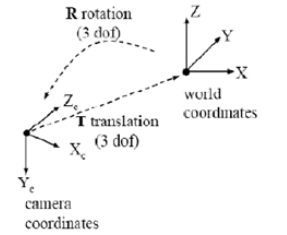
When it comes to camera calibration, we have to talk about camera coordinate system, world coordinate system and image coordinate system.
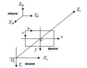
The above figure is a schematic diagram of the three coordinates, through which you can have an intuitive understanding of the three coordinates.
World coordinate system (XW,YW,ZW): the reference system for the position of the target object. In addition to infinity, world coordinates can be placed freely according to the convenience of operation. The unit is length, such as mm.. In binocular vision, the world coordinate system has three main uses:
1. Determine the position of the calibration object during calibration;
2. As the system reference system of binocular vision, the relationship between two cameras relative to the world coordinate system is given, so as to calculate the relative relationship between cameras;
3. As a container for the reconstruction of three-dimensional coordinates, it stores the three-dimensional coordinates of the reconstructed object. The world coordinate system is the first station to incorporate the object in sight into the operation.
Camera coordinate system (XC,YC,ZC): the coordinate system of the object measured by the camera from its own angle. The origin of the camera coordinate system is on the optical center of the camera, and the z-axis is parallel to the optical axis of the camera. It is the bridgehead connecting with the photographed object. The object in the world coordinate system needs to go through the rigid body change to the camera coordinate system, and then have a relationship with the image coordinate system. It is the link between image coordinates and world coordinates, and communicates the furthest distance in the world. The unit is length, such as mm.
Image coordinate system (x,y): Taking the center of CCD image plane as the coordinate origin, it is introduced to describe the projection transmission relationship between the object from the camera coordinate system to the image coordinate system in the imaging process, so as to further obtain the coordinates under the pixel coordinate system. The image coordinate system represents the position of pixels in the image in physical units (such as millimeters).
Pixel coordinate system (u,v): Taking the vertex of the upper left corner of the CCD image plane as the origin, it is introduced to describe the coordinates of the image points of the object after imaging on the digital image (photo). It is the coordinate system where we really read the information from the camera. Pixel coordinate system is the image coordinate system in pixels.
(Note:) many people combine the image coordinate system with the pixel coordinate system, which is called the three coordinate systems, while others separate it, which is called the four coordinate systems.
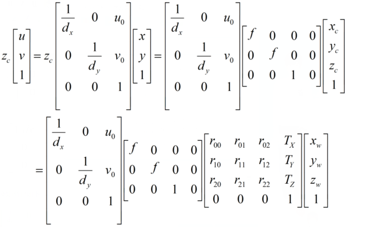
1. Image coordinate system to pixel coordinate system
At this point, you may ask why we need to build a pixel coordinate system with an image coordinate system?
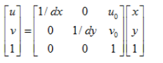
Taking the upper left corner of the image as the origin, we establish a direct coordinate system u-v in pixels. The abscissa u and ordinate v of a pixel are the number of columns and rows in its image array respectively.
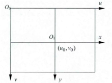
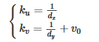
Since (u,v) only represents the number of columns and rows of pixels, and the position of pixels in the image is not expressed in physical units, we also need to establish an image coordinate system x-y expressed in physical units (such as millimeters). The intersection of the camera optical axis and the image plane (generally located at the center of the image plane, also known as the principal point of the image) is defined as the origin O1 of the coordinate system, and the x-axis is parallel to the u-axis, and the y-axis is parallel to the v-axis. It is assumed that (u0,v0) represents the positioning of O1 in the u-v coordinate system, and dx and dy represent the physical dimensions of each pixel on the horizontal axis X and vertical axis Y respectively, Then there is the following relationship between the coordinates of each pixel in the image in the u-v coordinate system and the coordinates in the x-y coordinate system:

Among them, we assume Physical coordinate system If the unit of dx is mm, the unit of dx is mm / pixel. Then the unit of x/dx is the pixel, which is the same as the unit of u. For ease of use, the above formula can be expressed in homogeneous coordinates and matrix form as:
In order to make you understand this content more directly, let's give an example. Since the image of the object photographed by the camera is projected onto the CCD chip (image plane) through the lens, we set the size of the CCD as 8x6mm, and the size of the captured image is 640x480, then dx=1/80mm / pixel, dy=1/80mm / pixel, u0=320,v0=240.
The matrix formula above uses homogeneous coordinates, which may confuse beginners. You will ask: how to convert ordinary coordinates into homogeneous coordinates? What benefits can homogeneous coordinates bring?
Here is a popular explanation for aligning sub coordinates. Here we only talk about how to rewrite ordinary coordinates into homogeneous coordinates and why to introduce homogeneous coordinates. Here is only a popular but less rigorous expression. Try to be simple and clear. For the rigorous pure mathematical derivation of homogeneous coordinates, see "higher geometry by Zhou Xinghe - 1.3 homogeneous coordinates on the extended plane". Corn has read the book "higher geometry" in detail, but he feels that it is a little far from computer vision. It is about the projection relationship of pure mathematics, which is more astringent and difficult to understand.
Homogeneous coordinates can be understood as adding a "small tail" after the original coordinates. To convert ordinary coordinates to homogeneous coordinates is usually to add a dimension with a value of 1. As the image coordinate system (u,v) is converted to (u,v,1). For infinity, the small tail is 0. Note that adding a small tail to the zero vector is mathematically meaningless.
So why should computer vision add this "little tail" in coordinate calculation?
1. Extend the projection plane to infinity. Such as the description of vanishing point.
2. Make the calculation more regular
If expressed in ordinary coordinates, it will look like the following:
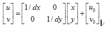
This form of operation will bring some trouble to the back and operation, so homogeneous coordinates is a better choice.
Homogeneous coordinates have another important property, scaling invariance. That is, if the homogeneous coordinate m is set, then α M=M.
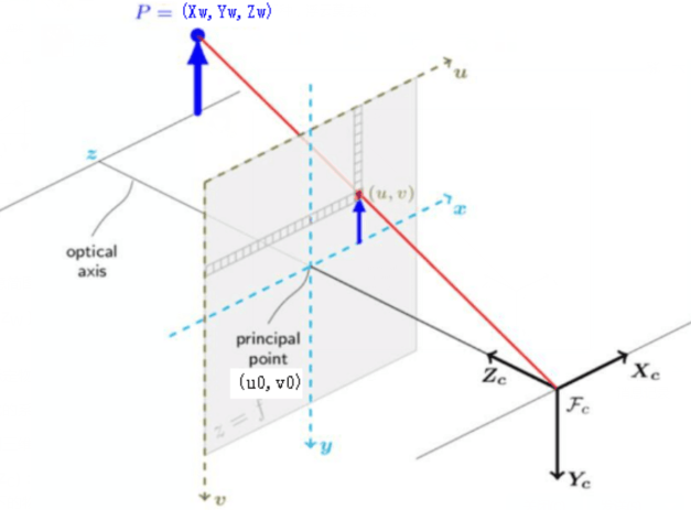
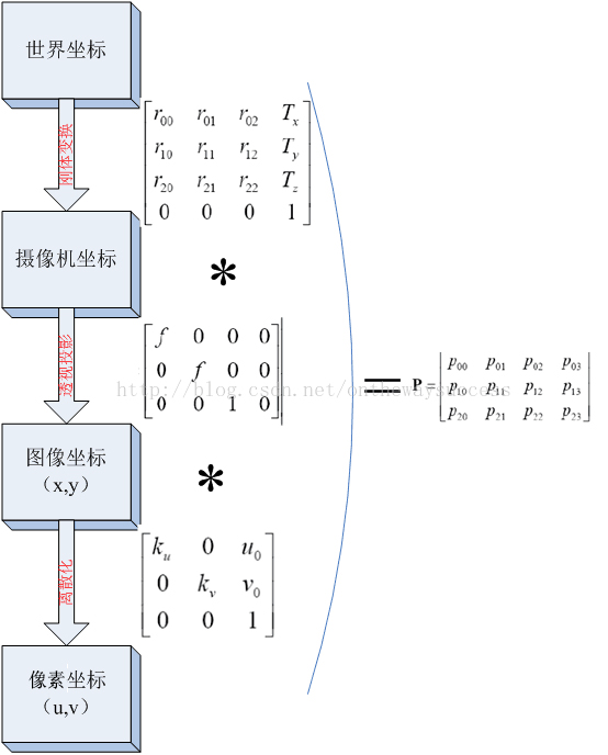
After introducing the pixel coordinate system, we will discuss the three coordinate systems again. We want to know the relationship between these three coordinate systems. Let's start with the following figure:
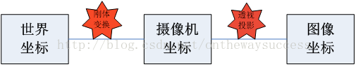
The figure shows that the world coordinate system reaches the camera coordinate system through rigid body transformation, and then the camera coordinate system reaches the image coordinate system through perspective projection transformation. It can be seen that the relationship between world coordinates and image coordinates is based on rigid body transformation and perspective projection transformation.
2. World coordinate system to camera coordinate system
First, let's take a look at how rigid body transformation connects the world coordinate system with the image coordinate system. Here, let's first introduce rigid body transformation:
Rigid body motion: three-dimensional space When an object does not deform geometry Object work rotate, translation of motion , called rigid bodyTransform.
Because the world coordinate system and camera coordinate system are both right-hand coordinate systems, they will not deform. We want to convert the coordinates under the world coordinate system to the coordinates under the camera coordinate, as shown in the figure below, which can be transformed by rigid body. A coordinate system in space can always be transformed into another coordinate system through rigid body transformation.
Let's take a look at the mathematical expression of rigid body transformation between the two:
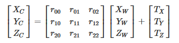
The corresponding homogeneous expression is:
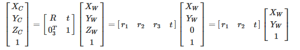
Where R is 3 × The orthogonal identity matrix (i.e. rotation matrix) of 3, t is the translation vector, and R and T are independent of the camera. Therefore, these two parameters are called the external parameters of the camera, which can be understood as the distance between the two coordinate origins. Because they are jointly controlled by the components in the X, y and Z directions, they have three degrees of freedom.
We assume that the plane of the object point in the world coordinate system passes through the origin of the world coordinate system and is perpendicular to the Zw axis (that is, the chessboard plane coincides with the XW YW plane for the convenience of subsequent calculation), then Zw=0.
3. Camera coordinate system to image coordinate system
First, let's take a look at how perspective projection connects the image coordinate system with the image coordinate system. Here, let's first introduce perspective projection:
Perspective projection: a single-sided projection that uses the central projection method to project the body onto the projection plane, so as to obtain a more close to the visual effect. It's a bit like a shadow play. It is in line with people's psychological habits, that is, the object close to the viewpoint is large, and the object far from the viewpoint is small. Parallel lines not parallel to the imaging plane will intersect the vanish point
Here we still take pinhole imaging as an example (except that the imaging brightness is low, the imaging effect is the same as perspective projection, but the light path is simpler)
The following figure is the basic model of pinhole camera. Plane π is called the image plane of the camera, and point Oc is called
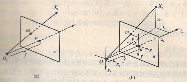
As shown in the figure, the image coordinate system is o-xy and the camera coordinate system is ox xcyczc
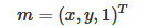
The homogeneous coordinates of its image point m in the image coordinate system are recorded as:
According to the triangle similarity principle, we can get:

We use the matrix as:
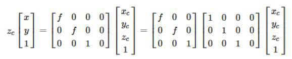
Note that due to the scaling invariance of homogeneous coordinates, zc[x,y,1]T and (x,y,1)T represent the same point.
4. Summary
We have introduced the conversion process between various coordinate systems, but what we want to know is how to convert from the world coordinate system to the pixel coordinate system, so we need to connect the above:
By multiplying the three, the three processes can be combined into a matrix:
We take the transformation matrix P from world coordinates to image coordinates as follows:
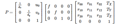
P represents a projection camera, which has the following formula:
Of which:
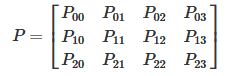
We set:
Finally, a picture is used to summarize the transformation relationship from the world coordinate system to the pixel coordinate system (without considering distortion):
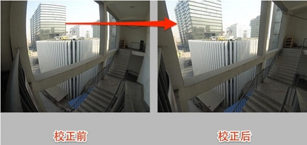
II. Picture correction
We talk about perspective projection in the transformation from camera coordinate system to image coordinate system. When the camera takes pictures, the real object is projected onto the image plane through the lens, but the lens will introduce distortion due to the deviation of manufacturing accuracy and assembly process, resulting in the distortion of the original image. Therefore, we need to consider the problem of imaging distortion.
Lens distortion is mainly divided into radial distortion and tangential distortion, as well as thin lens distortion and so on, but there is no significant impact of radial and tangential distortion, so we only consider radial and tangential distortion here.
Radial distortion
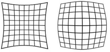
As the name suggests, radial distortion is the distortion distributed along the radius of the lens. The reason is that the light at the center of the principle lens is more curved than near the center. This distortion is more obvious in ordinary cheap lenses. Radial distortion mainly includes barrel distortion and pillow distortion. The following are the schematic diagrams of pillow and barrel distortion respectively:
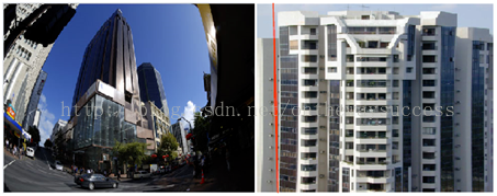
They look like this in real photos:
The distortion of the center of the image plane is 0. It moves to the edge along the radius of the lens, and the distortion is more and more serious. The mathematical model of distortion can be described by the first few terms of Taylor series expansion around the principal point. Usually, the first two terms, k1 and k2, are used. For lenses with great distortion, such as fisheye lens, the third term k3 can be added for description. According to the distribution position of a point on the imager in the radial direction, the adjustment formula is:
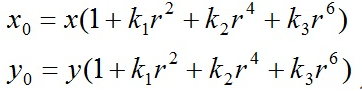
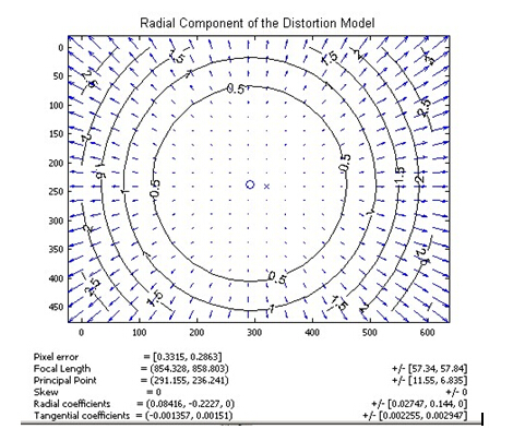
Where (x0, y0) is the original position of the distortion point in the image plane, and (x, y) is the new position after the distortion is corrected. The following figure is the offset diagram of the point position after the point at different distances from the optical center passes through the lens radial distortion. It can be seen that the farther away from the optical center, the greater the radial displacement, the greater the distortion, and there is almost no offset near the optical center.
Tangential distortion
Tangential distortion is caused by the fact that the lens itself is not parallel to the camera sensor plane (image plane) or image plane. This situation is mostly caused by the installation deviation of the lens pasted on the lens module. The distortion model can be described by two additional parameters p1 and p2:
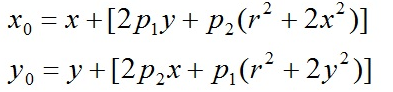
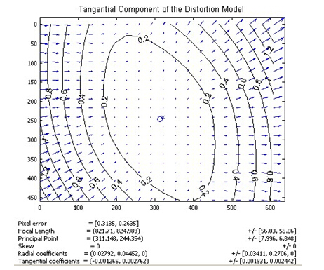
The following figure shows the schematic diagram of tangential distortion of a lens. Generally, the distortion displacement is symmetrical relative to the connecting line between the lower left corner and the upper right corner, indicating that the lens has a rotation angle perpendicular to this direction.
There are five distortion parameters in the radial distortion and tangential distortion models. In Opencv, they are arranged into a 5 * 1 matrix, including k1, k2, p1, p2 and k3 in turn. It is often defined as the form of Mat matrix, such as Mat distCoeffs=Mat (1,5, CV_32FC1, Scalar::all (0)); These five parameters are the five distortion coefficients of the camera that need to be determined in camera calibration. After obtaining these five parameters, the image distortion caused by lens distortion can be corrected. The following figure shows the effect after correction according to lens distortion coefficient:
3, Zhang's calibration method
The purpose of camera calibration is to establish the relationship between camera image pixel position and object space position, that is, the relationship between world coordinate system and image coordinate system. The method is to solve the camera model parameters from the coordinates of known feature points according to the camera model, so that the three-dimensional coordinates of spatial points can be recovered from the image, that is, three-dimensional reconstruction. Therefore, the parameters required for the solution include 4 internal parameters and 5 distortion parameters, as well as external parameters, rotation matrix and translation matrix.
"Zhang's calibration" refers to the camera calibration method of single plane checkerboard proposed by Professor Zhang Zhengyou in 1998. Zhang's calibration method has been widely used as a toolbox or encapsulated function. The original text of Zhang's calibration is "a flexible new technology for camera calibration". The method mentioned in this paper provides great convenience for camera calibration and has high accuracy. From then on, there is no need for special calibration objects, only a printed checkerboard.
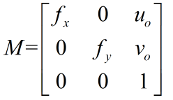
In the above, we have obtained the coordinate mapping relationship between the pixel coordinate system and the world coordinate system. Assuming that the calibration chessboard is located in the plane of zw=0 in the world coordinate, we simplify the formula in the previous text:
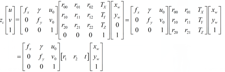
Where, u and V represent the coordinates in the pixel coordinate system, fx=f/dx,fy=f/dy,u0, x0, γ (the two coordinate axis deflection parameters caused by manufacturing error are usually very small, and the value obtained by matrix operation above is 0). It represents 5 camera internal parameters, R and t represent camera external parameters, and XW, YW and ZW represent coordinates in the world coordinate system.
The relationship between fx,fy and physical focal length f is: fx=fsx and fy=fsy. Where sx=1/dx represents the pixel value represented by the 1 mm length in the x direction, i.e. pixel / unit mm. FX and FY are calculated as a whole in camera calibration, not through this formula.
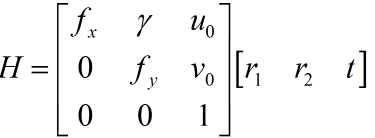
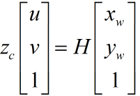
Homography (defined as the projection mapping from one plane to another in computer vision) matrix is defined as:
Now there are:
What if we take the value of H?
We can analyze three times of H * as a matrix. Therefore, H has 8 unknowns to be solved.
(xw,yw) as the spatial coordinates of the calibration object, which can be manually controlled by the designer, is a known quantity. (u,v) is the pixel coordinate, which can be obtained directly from the camera. For a set of correspondence (xw,yw)-(u,v), we can obtain two sets of equations.
Now there are eight unknowns to solve, so we need at least eight equations. So we need four corresponding points. The homography matrix H from the image plane to the world plane can be calculated by four points.
This is also one reason why Zhang's calibration uses the chessboard with four corners as the calibration object. Zhang's calibration is to use a printed checkerboard, and then mark each corner, its pixel coordinates in the pixel coordinate system and its coordinates in the world coordinate system. Zhang's calibration proves that the value of H matrix can be solved through more than 4 groups of points. However, in order to reduce errors and have stronger robustness, we generally take many photos, Select a large number of corners for calibration. The specific process is as follows:
- Print a checkerboard calibration drawing and paste it on the surface of a plane object
- Taking a group of pictures of checkerboards in different directions can be realized by moving the camera or moving the calibration picture.
- For each chessboard picture taken, detect the characteristic points of all chessboard squares in the picture (corner, that is, the intersection of black and white chessboard in the figure below, and a corner is in the magenta circle in the middle). We define that the printed chessboard drawing is located on the plane of the world coordinate system zw=0, and the origin of the world coordinate system is located at a fixed corner of the chessboard drawing (such as the yellow dot in the figure below). The origin of the pixel coordinate system is located in the upper left corner of the picture.
- Because the spatial coordinates of all corners in the chessboard calibration drawing are known, and the pixel coordinates of these corners corresponding to the corners in the captured calibration picture are also known. If we get such n > = 4 matching point pairs (the more the calculation results are, the more robust), we can obtain the homography matrix H according to LM and other optimization methods.
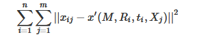
Professor Zhang Zhengyou proved the feasibility of Zhang's calibration algorithm from mathematical derivation. However, in the actual calibration process, the maximum likelihood estimation is generally used for optimization. Suppose we take n calibration pictures, and there are m checkerboard corners in each picture. The two-dimensional pixels obtained from the three-dimensional space point Xj(xw,yw,zw) after the transformation of the camera's internal parameters m, external parameters R, t are x '(u,v). Assuming that the noise is independent and identically distributed, we solve the above maximum likelihood estimation problem by minimizing the position of Xij (actual value: the actual value of the chessboard corner in the pixel coordinate system) and X' (estimated value):
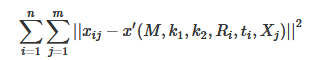
Now let's consider the influence of lens distortion. Since the influence of radial distortion is relatively obvious, we mainly consider the radial distortion parameters. According to experience, we usually only consider the first two parameters K1 and K2 of radial distortion (adding more parameters will make the model complex and unstable). In the actual solution, K1 and K2 are usually added as parameters to the above functions for optimization. The functions to be optimized are as follows:
Maximum likelihood estimation is a method to estimate the total unknown parameters. It is mainly used for point estimation. The so-called point estimation refers to using the observed value of an estimator to estimate the true value of an unknown parameter. To put it bluntly, it is to select the parameter in the parameter space that maximizes the probability of the sample obtaining the observed value.
Here I don't introduce the mathematical derivation process of Zhang's calibration method too much. Children's shoes interested can see the link given at the end of the blog.
Suppose we have obtained the internal parameter M and external parameter R,t of the camera through LM. If the two-dimensional coordinates in the image are obtained, how to obtain the three-dimensional coordinates in reality? Of course, the monocular camera cannot obtain the three-dimensional coordinates, but it can reflect a certain relationship. To sum up, the matrix transformation formula is:
According to the transformation between coordinate systems and camera model, the knowledge of polar geometry and basic matrix are studied. It is proved that the basic matrix is the key to obtain the camera projection matrix. According to the basic matrix F and the internal parameter matrix M obtained in the camera calibration stage, the eigenmatrix e is calculated, and the external parameter matrices R and T are obtained by singular value decomposition of E. then the projection matrices P1, P2 Re projection matrix Q. OpenCV provides two related functions: stereoCalibrate() and stereoRectify().
4, Monocular calibration using opencv
Purpose of camera calibration: obtain the internal and external parameter matrix of the camera (at the same time, the selection and translation matrix of each calibrated image will be obtained). The internal and external parameter coefficients can correct the image taken by the camera and obtain the image with relatively small distortion.
Input of camera calibration: the image coordinates of all internal corners on the calibration image and the spatial three-dimensional coordinates of all internal corners on the calibration board image (generally, it is assumed that the image is located on the Z=0 plane).
Output of camera calibration: internal and external parameter coefficients of camera.
These three basic problems determine the complete process of using Opencv to calibrate the camera with Zhang Zhengyou method, evaluate the calibration results and correct the original image with the calibration results:
- 1. Prepare calibration picture
- 2. Extract corner information for each calibration picture
- 3. For each calibration image, sub-pixel corner information is further extracted
- 4. Draw the found inner corner on the chessboard calibration diagram (not necessary, only for display)
- 5. Camera calibration
- 6. Evaluate the calibration results
- 7. Check the calibration effect - use the calibration results to correct the chessboard diagram
Prepare calibration picture
Calibration pictures need to be taken with a calibration board at different positions, angles and attitudes. At least 3 pictures are required, preferably 10 ~ 20. The calibration board needs to be a checkerboard composed of black-and-white rectangles, which requires high manufacturing accuracy.
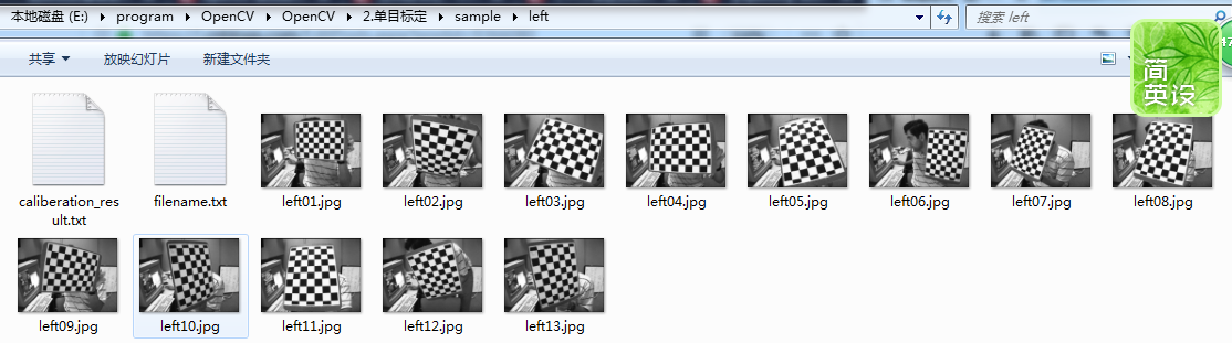
Here we use the calibration image in the sample program provided by OpenCV. The image is located in the installation path of opencv(C + + version): opencv\sources\samples\data:
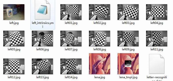
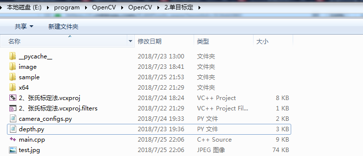
We first create a C + + console project and store the calibration pictures in the following format:
There are two folders left and right under the sample folder, which correspond to the calibration board pictures taken by the left camera and the right camera respectively:
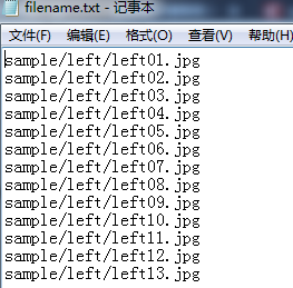
filename.txt the path where the calibration image is stored, as follows:
About the API functions provided by OpenCV for camera calibration, you can check the blog Explanation of binocular vision calibration procedure , the code of single target is as follows:
/*************************************************************************************
*
*Description: camera calibration, Zhang's calibration method, monocular calibration
*   Author     : JNU
*   Data       : 2018.7.22
*
************************************************************************************/
#include <opencv2/core/core.hpp>
#include <opencv2/imgproc/imgproc.hpp>
#include <opencv2/calib3d/calib3d.hpp>
#include <opencv2/highgui/highgui.hpp>
#include <iostream>
#include <fstream>
#include <vector>
using namespace cv;
using namespace std;
void main(char *args)
{
//Save file name
std::vector<std::string> filenames;
</span><span style="color:#008000;">//</span><span style="color:#008000;"> Parameters to be changed
</span><span style="color:#008000;">//</span><span style="color:#008000;"> For left camera calibration, specify the image path of the left camera and save the calibration result file</span>
<span style="color:#0000ff;">string</span> infilename = <span style="color:#800000;">"</span><span style="color:#800000;">sample/left/filename.txt</span><span style="color:#800000;">"</span>;        <span style="color:#008000;">//</span><span style="color:#008000;"> If it is a right camera, change left to right</span>
<span style="color:#0000ff;">string</span> outfilename = <span style="color:#800000;">"</span><span style="color:#800000;">sample/left/caliberation_result.txt</span><span style="color:#800000;">"</span><span style="color:#000000;">;

</span><span style="color:#008000;">//</span><span style="color:#008000;"> The path of the image file used for calibration. Each line saves a path of the calibration image. ifstream is read from the hard disk to the memory</span>
ifstream fin(infilename);
//Save the calibration result ofstream is written from memory to hard disk
ofstream fout(outfilename);
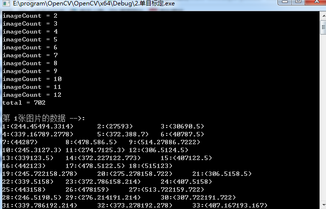
</span><span style="color:#008000;">/*</span><span style="color:#008000;"> 1.Read each image, extract corners from it, and then sub-pixel refine the corners to obtain the coordinates of each corner in the pixel coordinate system The origin of the pixel coordinate system is located in the upper left corner of the image </span><span style="color:#008000;">*/</span><span style="color:#000000;"> std::cout </span><< <span style="color:#800000;">"</span><span style="color:#800000;">Start extracting corners......</span><span style="color:#800000;">"</span> <<<span style="color:#000000;"> std::endl;; </span><span style="color:#008000;">//</span><span style="color:#008000;"> Number of images</span> <span style="color:#0000ff;">int</span> imageCount = <span style="color:#800080;">0</span><span style="color:#000000;">; </span><span style="color:#008000;">//</span><span style="color:#008000;"> Image size</span>
cv::Size imageSize;
//Number of corners per row and column on the calibration board
cv::Size boardSize = cv::Size(9, 6);
//Cache detected corners on each image
std::vector<Point2f> imagePointsBuf;
//Save all detected corners
std::vector<std::vector<Point2f>> imagePointsSeq;
char filename[100];
if (fin.is_open())
{
//Finished reading?
while (!fin.eof())
{
//Read one line at a time
fin.getline(filename, sizeof(filename) / sizeof(char));
//Save file name
filenames.push_back(filename);
//Read picture
Mat imageInput = cv::imread(filename);
//Get the width and height information when reading the first picture
if (imageCount == 0)
{
imageSize.width = imageInput.cols;
imageSize.height = imageInput.rows;
std::cout << "imageSize.width = " << imageSize.width << std::endl;
std::cout << "imageSize.height = " << imageSize.height << std::endl;
}
std::cout </span><< <span style="color:#800000;">"</span><span style="color:#800000;">imageCount = </span><span style="color:#800000;">"</span> << imageCount <<<span style="color:#000000;"> std::endl;
imageCount</span>++<span style="color:#000000;">;
</span><span style="color:#008000;">//</span><span style="color:#008000;"> Extract the corners of each picture</span>
<span style="color:#0000ff;">if</span> (cv::findChessboardCorners(imageInput, boardSize, imagePointsBuf) == <span style="color:#800080;">0</span><span style="color:#000000;">)
{
</span><span style="color:#008000;">//</span><span style="color:#008000;"> Corner not found</span>
std::cout << <span style="color:#800000;">"</span><span style="color:#800000;">Can not find chessboard corners!</span><span style="color:#800000;">"</span> <<<span style="color:#000000;"> std::endl;
exit(</span><span style="color:#800080;">1</span><span style="color:#000000;">);
}
</span><span style="color:#0000ff;">else</span><span style="color:#000000;">
{
Mat viewGray;
</span><span style="color:#008000;">//</span><span style="color:#008000;"> Convert to grayscale image</span>
cv::cvtColor(imageInput, viewGray, cv::COLOR_BGR2GRAY);
//Sub-pixel precision is used to refine the roughly extracted corners
cv::find4QuadCornerSubpix(viewGray, imagePointsBuf, cv::Size(5, 5));
//Save subpixels
imagePointsSeq.push_back(imagePointsBuf);
//Show corner position on image
cv::drawChessboardCorners(viewGray, boardSize, imagePointsBuf, true);
//Display picture
//cv::imshow("Camera Calibration", viewGray);
cv::imwrite("test.jpg", viewGray);
//Wait for 0.5s
//waitKey(500);
}
}
</span><span style="color:#008000;">//</span><span style="color:#008000;"> Calculate the number of corners on each picture 54</span>
<span style="color:#0000ff;">int</span> cornerNum = boardSize.width *<span style="color:#000000;"> boardSize.height;
</span><span style="color:#008000;">//</span><span style="color:#008000;"> Total number of corners</span>
<span style="color:#0000ff;">int</span> total = imagePointsSeq.size()*<span style="color:#000000;">cornerNum;
std::cout </span><< <span style="color:#800000;">"</span><span style="color:#800000;">total = </span><span style="color:#800000;">"</span> << total <<<span style="color:#000000;"> std::endl;
</span><span style="color:#0000ff;">for</span> (<span style="color:#0000ff;">int</span> i = <span style="color:#800080;">0</span>; i < total; i++<span style="color:#000000;">)
{
</span><span style="color:#0000ff;">int</span> num = i /<span style="color:#000000;"> cornerNum;
</span><span style="color:#0000ff;">int</span> p = i%<span style="color:#000000;">cornerNum;
</span><span style="color:#008000;">//</span><span style="color:#008000;"> Cornernum is the number of corners of each picture. This judgment statement is for output and easy debugging</span>
<span style="color:#0000ff;">if</span> (p == <span style="color:#800080;">0</span><span style="color:#000000;">)
{
std::cout </span><< <span style="color:#800000;">"</span><span style="color:#800000;">\n The first </span><span style="color:#800000;">"</span> << num+<span style="color:#800080;">1</span> << <span style="color:#800000;">"</span><span style="color:#800000;">Data of picture -->: </span><span style="color:#800000;">"</span> <<<span style="color:#000000;"> std::endl;
}
</span><span style="color:#008000;">//</span><span style="color:#008000;"> Output all corners</span>
std::cout<<p+<span style="color:#800080;">1</span><<<span style="color:#800000;">"</span><span style="color:#800000;">:(</span><span style="color:#800000;">"</span><<<span style="color:#000000;"> imagePointsSeq[num][p].x;
std::cout </span><< imagePointsSeq[num][p].y<<<span style="color:#800000;">"</span><span style="color:#800000;">)\t</span><span style="color:#800000;">"</span><span style="color:#000000;">;
</span><span style="color:#0000ff;">if</span> ((p+<span style="color:#800080;">1</span>) % <span style="color:#800080;">3</span> == <span style="color:#800080;">0</span><span style="color:#000000;">)
{
std::cout </span><<<span style="color:#000000;"> std::endl;
}
}
std::cout </span><< <span style="color:#800000;">"</span><span style="color:#800000;">Corner extraction completed!</span><span style="color:#800000;">"</span> <<<span style="color:#000000;"> std::endl;
</span><span style="color:#008000;">/*</span><span style="color:#008000;">
2.The origin of the camera calibration world coordinate system is located in the upper left corner of the calibration plate (the upper left corner of the first grid)
</span><span style="color:#008000;">*/</span><span style="color:#000000;">
std::cout </span><< <span style="color:#800000;">"</span><span style="color:#800000;">Start calibration</span><span style="color:#800000;">"</span> <<<span style="color:#000000;"> std::endl;
</span><span style="color:#008000;">//</span><span style="color:#008000;"> The three-dimensional information of the chessboard sets the coordinates of the chessboard in the world coordinate system
</span><span style="color:#008000;">//</span><span style="color:#008000;"> The size of each checkerboard on the calibration board is obtained by actual measurement</span>
cv::Size squareSize = cv::Size(<span style="color:#800080;">26</span>, <span style="color:#800080;">26</span><span style="color:#000000;">);
</span><span style="color:#008000;">//</span><span style="color:#008000;"> Number of corners per picture</span>
std::vector<<span style="color:#0000ff;">int</span>><span style="color:#000000;"> pointCounts;
</span><span style="color:#008000;">//</span><span style="color:#008000;"> Save the three-dimensional coordinates of the corners on the calibration plate</span>
std::vector<std::vector<cv::Point3f>><span style="color:#000000;"> objectPoints;
</span><span style="color:#008000;">//</span><span style="color:#008000;"> Camera internal parameter matrix M=[fx] γ u0,0 fy v0,0 0 1]</span>
cv::Mat cameraMatrix = cv::Mat(<span style="color:#800080;">3</span>, <span style="color:#800080;">3</span>, CV_64F, Scalar::all(<span style="color:#800080;">0</span><span style="color:#000000;">));
</span><span style="color:#008000;">//</span><span style="color:#008000;"> Five distortion coefficients K1, K2, P1, P2 and K3 of the camera</span>
cv::Mat distCoeffs = cv::Mat(<span style="color:#800080;">1</span>, <span style="color:#800080;">5</span>, CV_64F, Scalar::all(<span style="color:#800080;">0</span><span style="color:#000000;">));
</span><span style="color:#008000;">//</span><span style="color:#008000;"> Rotation vector of each picture</span>
std::vector<cv::Mat><span style="color:#000000;"> tvecsMat;
</span><span style="color:#008000;">//</span><span style="color:#008000;"> Translation vector of each picture</span>
std::vector<cv::Mat><span style="color:#000000;"> rvecsMat;
</span><span style="color:#008000;">//</span><span style="color:#008000;"> Initialize the three-dimensional coordinates of the corner on the calibration plate</span>
<span style="color:#0000ff;">int</span><span style="color:#000000;"> i, j, t;
</span><span style="color:#0000ff;">for</span> (t = <span style="color:#800080;">0</span>; t < imageCount; t++<span style="color:#000000;">)
{
std::vector</span><cv::Point3f><span style="color:#000000;"> tempPointSet;
</span><span style="color:#008000;">//</span><span style="color:#008000;"> Number of rows</span>
<span style="color:#0000ff;">for</span> (i = <span style="color:#800080;">0</span>; i < boardSize.height; i++<span style="color:#000000;">)
{
</span><span style="color:#008000;">//</span><span style="color:#008000;"> Number of columns</span>
<span style="color:#0000ff;">for</span> (j = <span style="color:#800080;">0</span>; j < boardSize.width; j++<span style="color:#000000;">)
{
cv::Point3f realPoint;
</span><span style="color:#008000;">//</span><span style="color:#008000;"> Suppose the calibration plate is placed on the plane with z=0 in the world coordinate system</ span>
realPoint.x = i*<span style="color:#000000;">squareSize.width;
realPoint.y </span>= j*<span style="color:#000000;">squareSize.height;
realPoint.z </span>= <span style="color:#800080;">0</span><span style="color:#000000;">;
tempPointSet.push_back(realPoint);
}
}
objectPoints.push_back(tempPointSet);
}
</span><span style="color:#008000;">//</span><span style="color:#008000;"> Initialize the number of corners in each image, assuming that the complete calibration board can be seen in each image</span>
<span style="color:#0000ff;">for</span> (i = <span style="color:#800080;">0</span>; i < imageCount; i++<span style="color:#000000;">)
{
pointCounts.push_back(boardSize.width</span>*<span style="color:#000000;">boardSize.height);
}
</span><span style="color:#008000;">//</span><span style="color:#008000;"> Start calibration</span>
cv::calibrateCamera(objectPoints, imagePointsSeq, imageSize, cameraMatrix, distCoeffs, rvecsMat, tvecsMat);
STD:: cout < < calibration completed < < STD:: endl;
//Evaluate the calibration results
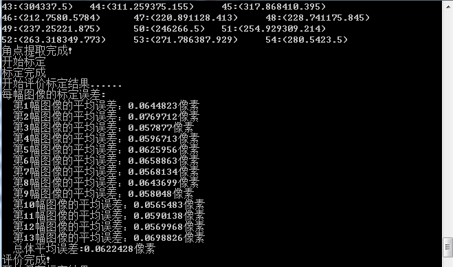
STD:: cout < < start evaluating calibration results... < < STD:: endl;
//The sum of the average errors of all images
double totalErr = 0.0;
//Average error of each image
double err = 0.0;
//Save the recalculated projection points
std::vector<cv::Point2f> imagePoints2;
STD:: cout < < calibration error of each image: "< STD:: endl;
Fout < < calibration error of each image: "< STD:: endl;
for (i = 0; i < imageCount; i++)
{
std::vector<cv::Point3f> tempPointSet = objectPoints[i];
//Through the obtained internal and external parameters of the camera, the three-dimensional points in the space are re projected and calculated to obtain a new projection point imagePoints2 (point coordinates in the pixel coordinate system)
cv::projectPoints(tempPointSet, rvecsMat[i], tvecsMat[i], cameraMatrix, distCoeffs, imagePoints2);
//Calculate the error between the new projection point and the old projection point
std::vector<cv::Point2f> tempImagePoint = imagePointsSeq[i];
cv::Mat tempImagePointMat = cv::Mat(1, tempImagePoint.size(), CV_32FC2);
cv::Mat imagePoints2Mat = cv::Mat(1, imagePoints2.size(), CV_32FC2);
for (int j = 0; j < tempImagePoint.size(); j++)
{
imagePoints2Mat.at<cv::Vec2f>(0, j) = cv::Vec2f(imagePoints2[j].x, imagePoints2[j].y);
tempImagePointMat.at<cv::Vec2f>(0, j) = cv::Vec2f(tempImagePoint[j].x, tempImagePoint[j].y);
}
//Calculates an absolute difference norm or a relative difference norm.
err = cv::norm(imagePoints2Mat, tempImagePointMat, NORM_L2);
totalErr += err /= pointCounts[i];
STD:: cout < < 1st < < I + 1 < < average error of image: "< err < < pixel < < endl;
Fout < < 1st < < I + 1 < < average error of image: < < err < < pixel < < endl;
}
</span><span style="color:#008000;">//</span><span style="color:#008000;"> Average total error per image</span>
std::cout << <span style="color:#800000;">"</span><span style="color:#800000;"> Overall average error:</span><span style="color:#800000;">"</span> << totalErr / imageCount << <span style="color:#800000;">"</span><span style="color:#800000;">pixel</span><span style="color:#800000;">"</span> <<<span style="color:#000000;"> std::endl;
fout </span><< <span style="color:#800000;">"</span><span style="color:#800000;">Overall average error:</span><span style="color:#800000;">"</span> << totalErr / imageCount << <span style="color:#800000;">"</span><span style="color:#800000;">pixel</span><span style="color:#800000;">"</span> <<<span style="color:#000000;"> std::endl;
std::cout </span><< <span style="color:#800000;">"</span><span style="color:#800000;">Evaluation completed!</span><span style="color:#800000;">"</span> <<<span style="color:#000000;"> std::endl;
</span><span style="color:#008000;">//</span><span style="color:#008000;"> Save calibration results</span>
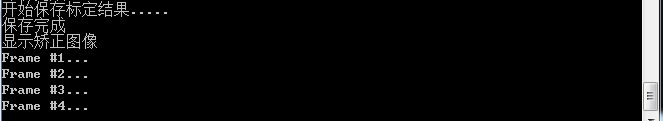
std::cout << <span style="color:#800000;">"</span><span style="color:#800000;">Start saving calibration results.....</span><span style="color:#800000;">"</span> <<<span style="color:#000000;"> std::endl;
</span><span style="color:#008000;">//</span><span style="color:#008000;"> Save the rotation matrix of each image</span>
cv::Mat rotationMatrix = cv::Mat(<span style="color:#800080;">3</span>, <span style="color:#800080;">3</span>, CV_32FC1, Scalar::all(<span style="color:#800080;">0</span><span style="color:#000000;">));
fout </span><< <span style="color:#800000;">"</span><span style="color:#800000;">Camera intrinsic parameter matrix:</span><span style="color:#800000;">"</span> <<<span style="color:#000000;"> std::endl;
fout </span><< cameraMatrix << std::endl <<<span style="color:#000000;"> std::endl;
fout </span><< <span style="color:#800000;">"</span><span style="color:#800000;">Distortion coefficient:</span><span style="color:#800000;">"</span> <<<span style="color:#000000;"> std::endl;
fout </span><< distCoeffs << std::endl <<<span style="color:#000000;"> std::endl;
</span><span style="color:#0000ff;">for</span> (<span style="color:#0000ff;">int</span> i = <span style="color:#800080;">0</span>; i < imageCount; i++<span style="color:#000000;">)
{
fout </span><< <span style="color:#800000;">"</span><span style="color:#800000;">The first</span><span style="color:#800000;">"</span> << i + <span style="color:#800080;">1</span> << <span style="color:#800000;">"</span><span style="color:#800000;">Rotation vector of an image:</span><span style="color:#800000;">"</span> <<<span style="color:#000000;"> std::endl;
fout </span><< tvecsMat[i] <<<span style="color:#000000;"> std::endl;
</span><span style="color:#008000;">//</span><span style="color:#008000;"> Convert the rotation vector into the corresponding rotation matrix</span>
cv::Rodrigues(tvecsMat[i], rotationMatrix);
Fout < < "the first" < < I + 1 < < "rotation matrix of image:" < STD:: endl;
fout << rotationMatrix << std::endl;
Fout < < 1st < < I + 1 < < translation vector of image: "< STD:: endl;
fout << rvecsMat[i] << std::endl;
}
STD:: cout < < save completed < < STD:: endl;
</span><span style="color:#008000;">/*</span><span style="color:#008000;">***********************************************************************
Display calibration results
************************************************************************</span><span style="color:#008000;">*/</span><span style="color:#000000;">
cv::Mat mapx </span>=<span style="color:#000000;"> cv::Mat(imageSize, CV_32FC1);
cv::Mat mapy </span>=<span style="color:#000000;"> cv::Mat(imageSize, CV_32FC1);
cv::Mat R </span>= cv::Mat::eye(<span style="color:#800080;">3</span>, <span style="color:#800080;">3</span><span style="color:#000000;">, CV_32F);
std::cout </span><< <span style="color:#800000;">"</span><span style="color:#800000;">Display correction image</span><span style="color:#800000;">"</span> <<<span style="color:#000000;"> endl;
</span><span style="color:#0000ff;">for</span> (<span style="color:#0000ff;">int</span> i = <span style="color:#800080;">0</span>; i != imageCount; i++<span style="color:#000000;">)
{
std::cout </span><< <span style="color:#800000;">"</span><span style="color:#800000;">Frame #</span><span style="color:#800000;">"</span> << i + <span style="color:#800080;">1</span> << <span style="color:#800000;">"</span><span style="color:#800000;">...</span><span style="color:#800000;">"</span> <<<span style="color:#000000;"> endl;
</span><span style="color:#008000;">//Calculate < / span > < span style = "color: #008000;" > Mapping matrix mapx and MAPY for image distortion correction (without stereo correction, dual photography is required for stereo correction)</span>
initUndistortRectifyMap(cameraMatrix, distCoeffs, R, cameraMatrix, imageSize, CV_32FC1, mapx, mapy);
//Read a picture
Mat imageSource = imread(filenames[i]);
Mat newimage = imageSource.clone();
//Another way is not to convert the matrix
//undistort(imageSource,newimage,cameraMatrix,distCoeffs);
//Make correction
remap(imageSource, newimage, mapx, mapy, INTER_LINEAR);
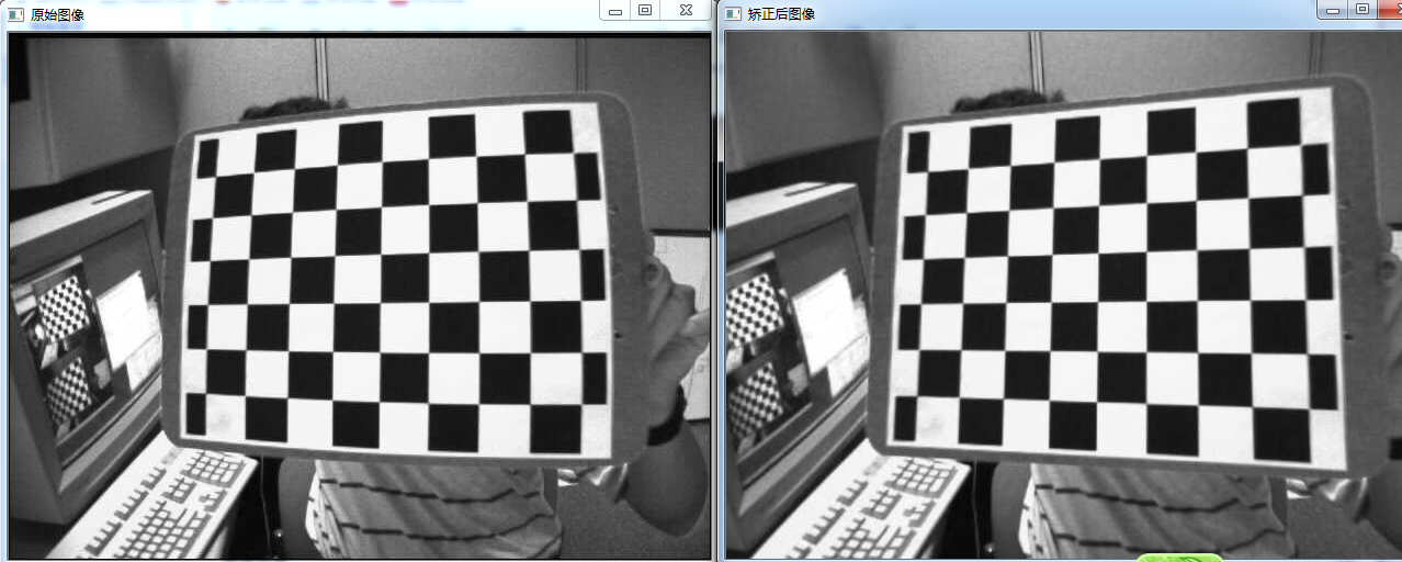
imshow("original image", imageSource);
imshow("corrected image", newimage);
waitKey();
}
</span><span style="color:#008000;">//</span><span style="color:#008000;"> Release resources</span>
fin.close();
fout.close();
system("pause");
}
}
The above two functions need to be introduced separately:
CV_EXPORTS_W void initUndistortRectifyMap( InputArray cameraMatrix, InputArray distCoeffs,
                           InputArray R, InputArray newCameraMatrix,
                           Size size, int m1type, OutputArray map1, OutputArray map2 );
Function function: this function is to calculate the mapping transformation matrix of distortion correction and camera stereo correction.
Parameter Description:
- cameraMatrix: input camera internal parameter matrix
- distCoeffs: input parameter, distortion coefficient of camera

There are 4, 5, 8, 12 or 14 elements. If this vector is empty, it is considered as zero distortion coefficient.
- R: The optional stereo correction transformation matrix is a 3 * 3 matrix.
stay
- newCameraMatrix: new camera internal parameter matrix
stay
- Size: undistorted image size.
- . m1type: the type of mapping of the first output, which can be CV_32FC1, CV_32FC2 or CV_16SC2, see cv::convertMaps.
- . map1: the first output map.
- . map2: second output map.
void remap(InputArray src, OutputArray dst, InputArray map1, InputArray
      map2, int interpolation,int borderMode=BORDER_CONSTANT, const Scalar&
      borderValue=Scalar())
Function function: Remapping: it is the process of placing pixels at a certain position in one image to the specified position in another image.
Parameter Description:
- src: the input image, i.e. the original image, requires a single channel 8-bit or floating-point image
- dst: the output image, i.e. the target image, needs the same size and type as the original image
- map1: it has two possible objects: (1) the first mapping of points (x,y); (2) Represents CV_16SC2,CV_32FC1, etc
- map2: it has two possible objects: (1) if map1 represents a point (x,y), this parameter does not represent any value; (2) Represents CV_16UC1,CV_ 32Y value of type FC1
- Interpolation: there are four interpolation methods:
(1)INTER_NEAREST -- nearest neighbor interpolation
(2)INTER_LINEAR -- bilinear interpolation (default)
(3)INTER_CUBIC -- double triple spline interpolation (default)
(4)INTER_LANCZOS4 - lanczos interpolation (default)
- borderMode: border mode, the default is BORDER_CONSTANT
- borderValue: boundary color. The default is Scalar() black
After the program runs, the internal and external parameters of the camera are saved in calibration_ result. Txt file, the contents are as follows:
Calibration error of each image:
Average error of the first image: 0.0644823 pixels
 Average error of the second image: 0.0769712 pixels
 Average error of the third image: 0.057877 pixels
 Average error of the fourth image: 0.0596713 pixels
 Average error of the fifth image: 0.0625956 pixels
 Average error of the 6th image: 0.0658863 pixels
 Average error of the seventh image: 0.0568134 pixels
 Average error of the 8th image: 0.0643699 pixels
 Average error of the 9th image: 0.058048 pixels
 Average error of the 10th image: 0.0565483 pixels
 Average error of the 11th image: 0.0590138 pixels
 Average error of the 12th image: 0.0569968 pixels
 Average error of the 13th image: 0.0698826 pixels
 Overall average error: 0.0622428 pixels
 Camera internal parameter matrix:
[530.5277314196954, 0, 338.8371277433631;
 0, 530.5883296858968, 231.5390118666163;
 0, 0, 1]
Distortion coefficient:
[-0.2581406917163123, -0.11124480187392, 0.0004630258905514519, -0.0009475605555950018, 0.413646790569884]
Image rotation vector 1:
[-75.22204622827574;
-109.7328226714255;
412.7511174854986]
Rotation matrix of the first image:
[0.9927105083879407, -0.1161407096490343, -0.03220531164846807;
0.1168004495051158, 0.9929655913965856, 0.01941621224214358;
0.02972375365863362, -0.02303627280285992, 0.999292664139887]
Translation vector of the first image:
[-1.985720132175791;
-2.010141521348128;
0.1175016759367312]
Rotation vector of the second image:
[-57.88571684656549;
88.73102475029921;
365.4767680110305]
Rotation matrix of the second image:
[-0.880518198944593, 0.2965025784551226, -0.36982958548071;
-0.4330747951156081, -0.8203927789645991, 0.3733656519530371;
-0.192701642865192, 0.4889191233652108, 0.8507785655767596]
Translation vector of the second image:
[-2.431974050326802;
-0.2015324617416875;
0.2103186188188722]
Rotation vector of the third image:
[-38.96229403649615;
-101.619482335263;
328.7991741655258]
Rotation matrix of the third image:
[0.7229826652152683, -0.6501194230369263, -0.2337537199455046;
0.6686409526220074, 0.7435854196067706, -1.49985835111166e-05;
0.1738256088007802, -0.1562864662674188, 0.9722958388199968]
Translation vector of the third image:
[1.726707502757928;
2.49410066154742;
-0.5169212442744683]
Rotation vector of the fourth image:
[-99.94408740929534;
-67.11904896100746;
341.7035262057663]
Rotation matrix of the 4th image:
[-0.4166240767662854, 0.8762113538151707, -0.2422355095852507;
-0.7194830230098562, -0.4806860756468779, -0.5012834290895748;
-0.5556694685325433, -0.03456240912595265, 0.8306845861192869]
Translation vector of the fourth image:
[-2.144507828065959;
-2.137658756455213;
0.3861555312888436]
Rotation vector of the 5th image:
[63.1817601794685;
-117.2855578733511;
327.5340459209377]
Rotation matrix of the 5th image:
[-0.1237680939389874, -0.9830519969136794, -0.1352413778646805;
0.8454470843144938, -0.03311262698003439, -0.5330316890754268;
0.5195196690663707, -0.1803117447603135, 0.8352167312468426]
Translation vector of the 5th image:
[-0.3394208745634724;
-2.941274925899604;
0.7239987875443074]
Rotation vector of the 6th image:
[176.6380486063267;
-65.02048705679623;
345.2669628180993]
Rotation matrix of the 6th image:
[-0.4823787195065527, 0.3144101256594393, 0.8175922234525194;
-0.5902636261183672, -0.8063068742380883, -0.03818476447485269;
0.6472245534965549, -0.5010144682933011, 0.5745301383843724]
Translation vector of the 6th image:
[0.144403698794371;
-2.686413562533621;
-0.08279238304814077]
Rotation vector of the 7th image:
[23.37912628758978;
-71.28708027930361;
401.7783087659996]
Rotation matrix of image 7:
[0.950756682549477, -0.3056521783663705, -0.05136610212392408;
0.3046663933949521, 0.9520979509442887, -0.02622747687825021;
0.05692204602107398, 0.009286423831555549, 0.9983354361181394]
Translation vector of the 7th image:
[0.4433620069430767;
-2.778035766165631;
0.1565310822654871]
Rotation vector of the 8th image:
[84.53413910746443;
-88.75268154189268;
326.4489757550855]
Rotation matrix of the 8th image:
[-0.882333219506006, -0.1387045774185431, 0.4497211691251699;
-0.1080922696912742, -0.870309912144045, -0.4804963247068739;
0.4580438308602738, -0.4725692510383723, 0.7529104541603049]
Translation vector of the 8th image:
[0.3026042878663719;
-2.832559861959414;
0.5197600078874884]
Rotation vector of the 9th image:
[-66.87955552666558;
-81.79728232518671;
287.3798612501427]
Rotation matrix of the 9th image:
[-0.06408698919457989, 0.997286705569611, 0.03622270986668297;
-0.8668814706204128, -0.03765202403427882, -0.4970903750638435;
-0.4943777641752957, -0.06325782149453277, 0.8669423708118097]
Translation vector of the 9th image:
[1.918018245182696;
2.198445482038513;
0.6398190872020209]
Rotation vector of the 10th image:
[51.38889872566385;
-112.4792732922813;
348.8614284720838]
Rotation matrix of the 10th image:
[0.8410751829508221, 0.5075468667660225, 0.1870527055678015;
-0.521221221444936, 0.852916565973049, 0.0293559159998552;
-0.1446408481020841, -0.1221863720908967, 0.9819111546039054]
Translation vector of the 10th image:
[0.2388869800501047;
2.534868757127185;
0.05816455567725017]
Rotation vector of the 11th image:
[55.25157597573984;
-103.974863603741;
332.3331998859927]
Rotation matrix of the 11th image:
[0.7603104175748064, -0.6302201082550355, -0.1573235013538499;
0.6075084686586226, 0.7756458925501082, -0.1711926104661106;
0.2299163531271294, 0.0345841657577196, 0.9725957053388442]
Translation vector of the 11th image:
[-0.02801590475009446;
-3.011578659457537;
0.5796308944847007]
Rotation vector of the 12th image:
[37.20265745451167;
-92.46700742075161;
299.3885458741333]
Rotation matrix of the 12th image:
[0.1968247409885918, -0.9604756585987335, -0.1968413843024444;
0.9041946443200382, 0.2554459280495449, -0.3423148010616344;
0.3790673640894628, -0.1106069034112951, 0.9187350251296783]
Translation vector of the 12th image:
[-0.4442257873668548;
-2.891665626351126;
-0.7306268697464358]
Rotation vector of the 13th image:
[49.15686896201693;
-109.7597615043953;
322.2472823512488]
Rotation matrix of the 13th image:
[-0.02527960043733595, 0.888126856668879, 0.4589026348422781;
-0.9835935284565535, 0.05992383782219021, -0.170155530145356;
-0.1786189031992861, -0.4556751256368033, 0.8720409779911538]
Translation vector of the 13th image:
[0.2685697410235677;
2.70549028727733;
0.2575020268614151]
A copy of the source code from other blogs is attached below:


/*************************************************************************************
*
*Description: camera calibration, Zhang's calibration method, monocular calibration, only one camera can be calibrated at a time
                 OPENCV3.0 monocular camera calibration (use the official calibration picture)
                 https://blog.csdn.net/zc850463390zc/article/details/48946855
*   Author     : JNU
*   Data       : 2018.7.22
*
************************************************************************************/
#include <opencv2/opencv.hpp>
#include <highgui.hpp>
#include "cv.h"
#include <cv.hpp>
#include <iostream>
using namespace std;
using namespace cv;
//Parameters that need to be changed before the program runs
//Use the official calibration picture set?
//#define SAMPLE
#define MY_DATA
#ifdef SAMPLE
/Official data set/
const int imageWidth = 640; // Camera resolution
const int imageHeight = 480;
const int boardWidth = 9; // Number of lateral corners
const int boardHeight = 6; // Longitudinal corner data
const int boardCorner = boardWidth * boardHeight; // Total corner data
const int frameNumber = 13; // Number of image frames to be used in camera calibration
const int squareSize = 20; // The size of the black-and-white grid of the calibration plate is in mm
const Size boardSize = Size(boardWidth, boardHeight);
const char imageFilePathFormat[] = “sample/right%02d.jpg”; // Image path for calibration, format string sample / left% 02D BMP indicates that the image path is sample / left01 bmp - sample/leftxx. bmp
#elif defined MY_DATA
//Own data
const int imageWidth = 1600; // Camera resolution
const int imageHeight = 1200;
const int boardWidth = 9; // Number of lateral corners
const int boardHeight = 6; // Longitudinal corner data
const int boardCorner = boardWidth * boardHeight; // Total corner data
const int frameNumber = 10; // Number of image frames to be used in camera calibration
const int squareSize = 30; // The size of the black-and-white grid of the calibration plate is in mm
const Size boardSize = Size(boardWidth, boardHeight);
Size imageSize = Size(imageWidth, imageHeight);
const char imageFilePathFormat[] = "image/right/%d.bmp";
#endif // SAMPLE
Mat intrinsic; // Camera internal parameters
Mat distortion_coeff; // Camera distortion parameters
vector<Mat> rvecs; // Rotation vector
vector<Mat> tvecs; // Translation vector
vector<vector<Point2f>> corners; // The set of corner points found in each image corresponds to objRealPoint one by one
vector<vector<Point3f>> objRealPoint; // The actual physical coordinate set of the corners of each sub image
vector<Point2f> corner; // Corner point found in a certain image
Mat rgbImage, grayImage;
/Calculate the actual physical coordinates of the module on the calibration board/
void calRealPoint(vector<vector<Point3f>>& obj, int boardwidth, int boardheight, int imgNumber, int squaresize)
{
// Mat imgpoint(boardheight, boardwidth, CV_32FC3,Scalar(0,0,0));
vector<Point3f> imgpoint;
for (int rowIndex = 0; rowIndex < boardheight; rowIndex++)
{
for (int colIndex = 0; colIndex < boardwidth; colIndex++)
{
// imgpoint.at<Vec3f>(rowIndex, colIndex) = Vec3f(rowIndex * squaresize, colIndex*squaresize, 0);
imgpoint.push_back(Point3f(rowIndex * squaresize, colIndex * squaresize, 0));
}
}
for (int imgIndex = 0; imgIndex < imgNumber; imgIndex++)
{
obj.push_back(imgpoint);
}
}
/The initial parameters of the camera can also be set without estimation/
void guessCameraParam(void)
{
/Allocate memory/
intrinsic.create(3, 3, CV_64FC1);
distortion_coeff.create(5, 1, CV_64FC1);
intrinsic.at< double>( 0, 1) = 0 ; intrinsic.at< double>( 1, 0) = 0 ; intrinsic.at< double>( 2, 0) = 0 ; intrinsic.at< double>( 2, 1) = 0 ; intrinsic.at< double>( 2, 2) = 1 ;</span><span style="color:#008000;">/*</span><span style="color:#008000;"> fx 0 cx 0 fy cy 0 0 1 </span><span style="color:#008000;">*/</span><span style="color:#000000;"> intrinsic.at</span><<span style="color:#0000ff;">double</span>>(<span style="color:#800080;">0</span>, <span style="color:#800080;">0</span>) = <span style="color:#800080;">256.8093262</span>; <span style="color:#008000;">//</span><span style="color:#008000;">fx </span> intrinsic.at<<span style="color:#0000ff;">double</span>>(<span style="color:#800080;">0</span>, <span style="color:#800080;">2</span>) = <span style="color:#800080;">160.2826538</span>; <span style="color:#008000;">//</span><span style="color:#008000;">cx</span> intrinsic.at<<span style="color:#0000ff;">double</span>>(<span style="color:#800080;">1</span>, <span style="color:#800080;">1</span>) = <span style="color:#800080;">254.7511139</span>; <span style="color:#008000;">//</span><span style="color:#008000;">fy</span> intrinsic.at<<span style="color:#0000ff;">double</span>>(<span style="color:#800080;">1</span>, <span style="color:#800080;">2</span>) = <span style="color:#800080;">127.6264572</span>; <span style="color:#008000;">//</span><span style="color:#008000;">cy</span>
</span><span style="color:#008000;">/*</span><span style="color:#008000;"> k1 k2 p1 p2 p3 </span><span style="color:#008000;">*/</span><span style="color:#000000;"> distortion_coeff.at</span><<span style="color:#0000ff;">double</span>>(<span style="color:#800080;">0</span>, <span style="color:#800080;">0</span>) = -<span style="color:#800080;">0.193740</span>; <span style="color:#008000;">//</span><span style="color:#008000;">k1</span> distortion_coeff.at<<span style="color:#0000ff;">double</span>>(<span style="color:#800080;">1</span>, <span style="color:#800080;">0</span>) = -<span style="color:#800080;">0.378588</span>; <span style="color:#008000;">//</span><span style="color:#008000;">k2</span> distortion_coeff.at<<span style="color:#0000ff;">double</span>>(<span style="color:#800080;">2</span>, <span style="color:#800080;">0</span>) = <span style="color:#800080;">0.028980</span>; <span style="color:#008000;">//</span><span style="color:#008000;">p1</span> distortion_coeff.at<<span style="color:#0000ff;">double</span>>(<span style="color:#800080;">3</span>, <span style="color:#800080;">0</span>) = <span style="color:#800080;">0.008136</span>; <span style="color:#008000;">//</span><span style="color:#008000;">p2</span> distortion_coeff.at<<span style="color:#0000ff;">double</span>>(<span style="color:#800080;">4</span>, <span style="color:#800080;">0</span>) = <span style="color:#800080;">0</span>; <span style="color:#008000;">//</span><span style="color:#008000;">p3</span>
}
void outputCameraParam(void)
{
/Save data/
//cvSave("cameraMatrix.xml", &intrinsic);
//cvSave("cameraDistoration.xml", &distortion_coeff);
//cvSave("rotatoVector.xml", &rvecs);
//cvSave("translationVector.xml", &tvecs);
<span style="color:#008000;">/*</span><span style="color:#008000;">Save data < / span > < span style = "color: #008000;" >*/</span>
<span style="color:#008000;">/*</span><span style="color:#008000;">Output data < / span > < span style = "color: #008000;" >*/</span><span style="color:#000000;">
FileStorage fs(</span><span style="color:#800000;">"</span><span style="color:#800000;">intrinsics.yml</span><span style="color:#800000;">"</span><span style="color:#000000;">, FileStorage::WRITE);
</span><span style="color:#0000ff;">if</span><span style="color:#000000;"> (fs.isOpened())
{
fs </span><< <span style="color:#800000;">"</span><span style="color:#800000;">intrinsic</span><span style="color:#800000;">"</span> << intrinsic << <span style="color:#800000;">"</span><span style="color:#800000;">distortion_coeff</span><span style="color:#800000;">"</span> <<<span style="color:#000000;"> distortion_coeff ;
fs.release();
}
</span><span style="color:#0000ff;">else</span><span style="color:#000000;">
{
cout </span><< <span style="color:#800000;">"</span><span style="color:#800000;">Error: can not save the intrinsics!!!!!</span><span style="color:#800000;">"</span> <<<span style="color:#000000;"> endl;
}
fs.open(</span><span style="color:#800000;">"</span><span style="color:#800000;">extrinsics.yml</span><span style="color:#800000;">"</span><span style="color:#000000;">, FileStorage::WRITE);
</span><span style="color:#0000ff;">if</span><span style="color:#000000;"> (fs.isOpened())
{
fs </span><< <span style="color:#800000;">"</span><span style="color:#800000;">rvecs</span><span style="color:#800000;">"</span> << rvecs << <span style="color:#800000;">"</span><span style="color:#800000;">tvecs</span><span style="color:#800000;">"</span> <<<span style="color:#000000;"> tvecs;
fs.release();
}
</span><span style="color:#0000ff;">else</span><span style="color:#000000;">
{
cout </span><< <span style="color:#800000;">"</span><span style="color:#800000;">Error: can not save the extrinsics parameters\n</span><span style="color:#800000;">"</span><span style="color:#000000;">;
}
</span><span style="color:#008000;">/*</span><span style="color:#008000;">Output data < / span > < span style = "color: #008000;" >*/</span><span style="color:#000000;">
cout </span><< <span style="color:#800000;">"</span><span style="color:#800000;">fx :</span><span style="color:#800000;">"</span> << intrinsic.at<<span style="color:#0000ff;">double</span>>(<span style="color:#800080;">0</span>, <span style="color:#800080;">0</span>) << endl << <span style="color:#800000;">"</span><span style="color:#800000;">fy :</span><span style="color:#800000;">"</span> << intrinsic.at<<span style="color:#0000ff;">double</span>>(<span style="color:#800080;">1</span>, <span style="color:#800080;">1</span>) <<<span style="color:#000000;"> endl;
cout </span><< <span style="color:#800000;">"</span><span style="color:#800000;">cx :</span><span style="color:#800000;">"</span> << intrinsic.at<<span style="color:#0000ff;">double</span>>(<span style="color:#800080;">0</span>, <span style="color:#800080;">2</span>) << endl << <span style="color:#800000;">"</span><span style="color:#800000;">cy :</span><span style="color:#800000;">"</span> << intrinsic.at<<span style="color:#0000ff;">double</span>>(<span style="color:#800080;">1</span>, <span style="color:#800080;">2</span>) <<<span style="color:#000000;"> endl;
cout </span><< <span style="color:#800000;">"</span><span style="color:#800000;">k1 :</span><span style="color:#800000;">"</span> << distortion_coeff.at<<span style="color:#0000ff;">double</span>>(<span style="color:#800080;">0</span>, <span style="color:#800080;">0</span>) <<<span style="color:#000000;"> endl;
cout </span><< <span style="color:#800000;">"</span><span style="color:#800000;">k2 :</span><span style="color:#800000;">"</span> << distortion_coeff.at<<span style="color:#0000ff;">double</span>>(<span style="color:#800080;">1</span>, <span style="color:#800080;">0</span>) <<<span style="color:#000000;"> endl;
cout </span><< <span style="color:#800000;">"</span><span style="color:#800000;">p1 :</span><span style="color:#800000;">"</span> << distortion_coeff.at<<span style="color:#0000ff;">double</span>>(<span style="color:#800080;">2</span>, <span style="color:#800080;">0</span>) <<<span style="color:#000000;"> endl;
cout </span><< <span style="color:#800000;">"</span><span style="color:#800000;">p2 :</span><span style="color:#800000;">"</span> << distortion_coeff.at<<span style="color:#0000ff;">double</span>>(<span style="color:#800080;">3</span>, <span style="color:#800080;">0</span>) <<<span style="color:#000000;"> endl;
cout </span><< <span style="color:#800000;">"</span><span style="color:#800000;">p3 :</span><span style="color:#800000;">"</span> << distortion_coeff.at<<span style="color:#0000ff;">double</span>>(<span style="color:#800080;">4</span>, <span style="color:#800080;">0</span>) <<<span style="color:#000000;"> endl;
}
void main(char *args)
{
Mat img;
int goodFrameCount = 0;
namedWindow("chessboard");
Cout < < press Q to exit... < < endl;
while (goodFrameCount < frameNumber)
{
char filename[100];
//sprintf_s(filename, "image/right/%d.bmp", goodFrameCount + 1);
sprintf_s(filename, imageFilePathFormat, goodFrameCount + 1);
// cout << filename << endl;
rgbImage = imread(filename, CV_LOAD_IMAGE_COLOR);
cvtColor(rgbImage, grayImage, CV_BGR2GRAY);
imshow("Camera", grayImage);
    </span><span style="color:#0000ff;">bool</span> isFind = findChessboardCorners(rgbImage, boardSize, corner, <span style="color:#800080;">0</span><span style="color:#000000;">);
    </span><span style="color:#0000ff;">if</span> (isFind == <span style="color:#0000ff;">true</span>)    <span style="color:#008000;">//</span><span style="color:#008000;"> All corners are found, which shows that this image is feasible</span>
{
/
Size(5,5) half the size of the search window
Size(-1,-1) half the size of the deadband
TermCriteria(CV_TERMCRIT_EPS | CV_TERMCRIT_ITER, 20, 0.1) iteration termination condition
/
cornerSubPix(grayImage, corner, Size(5, 5), Size(-1, -1), TermCriteria(CV_TERMCRIT_EPS | CV_TERMCRIT_ITER, 20, 0.1));
drawChessboardCorners(rgbImage, boardSize, corner, isFind);
imshow("chessboard", rgbImage);
corners.push_back(corner);
//string filename = "res\image\calibration";
//filename += goodFrameCount + ".jpg";
//cvSaveImage(filename.c_str(), &IplImage(rgbImage)); // Save the qualified pictures
goodFrameCount++;
cout << "The image is good" << endl;
}
else
{
cout << goodFrameCount+1 <<" The image is bad please try again" << endl;
}
// cout << "Press any key to continue..." << endl;
// waitKey(0);
    <span style="color:#0000ff;">if</span> (waitKey(<span style="color:#800080;">10</span>) == <span style="color:#800000;">'</span><span style="color:#800000;">q</span><span style="color:#800000;">'</span><span style="color:#000000;">)
    {
        </span><span style="color:#0000ff;">break</span><span style="color:#000000;">;
    }
    </span><span style="color:#008000;">//</span><span style="color:#008000;">    imshow("chessboard", rgbImage);</span>
}
</span><span style="color:#008000;">/*</span><span style="color:#008000;"> After image acquisition, start camera calibration calibrateCamera() Enter the actual physical coordinates of the corner of the parameter objectPoints imagePoints Image coordinates of corners imageSize Image size Output parameters cameraMatrix Internal parameter matrix of camera distCoeffs Camera distortion parameters rvecs Rotation vector (external parameter) tvecs Translation vector (external parameter) </span><span style="color:#008000;">*/</span> <span style="color:#008000;">/*</span><span style="color:#008000;">Set the actual initial parameters according to the calibrateCamera. If flag = 0, you can also not set < / span > < span style = "color: #008000;" >*/</span><span style="color:#000000;"> guessCameraParam(); cout </span><< <span style="color:#800000;">"</span><span style="color:#800000;">guess successful</span><span style="color:#800000;">"</span> <<<span style="color:#000000;"> endl; </span><span style="color:#008000;">/*</span><span style="color:#008000;">Calculate the three-dimensional coordinates of the actual correction point < / span > < span style = "color: #008000;" >*/</span><span style="color:#000000;"> calRealPoint(objRealPoint, boardWidth, boardHeight, frameNumber, squareSize); cout </span><< <span style="color:#800000;">"</span><span style="color:#800000;">cal real successful</span><span style="color:#800000;">"</span> <<<span style="color:#000000;"> endl; </span><span style="color:#008000;">/*</span><span style="color:#008000;">Calibrate the camera < / span > < span style = "color: #008000;" >*/</span><span style="color:#000000;"> calibrateCamera(objRealPoint, corners, Size(imageWidth, imageHeight), intrinsic, distortion_coeff, rvecs, tvecs, </span><span style="color:#800080;">0</span><span style="color:#000000;">); cout </span><< <span style="color:#800000;">"</span><span style="color:#800000;">calibration successful</span><span style="color:#800000;">"</span> <<<span style="color:#000000;"> endl; </span><span style="color:#008000;">/*</span><span style="color:#008000;">Save and output the parameter < / span > < span style = "color: #008000;" >*/</span><span style="color:#000000;"> outputCameraParam(); cout </span><< <span style="color:#800000;">"</span><span style="color:#800000;">out successful</span><span style="color:#800000;">"</span> <<<span style="color:#000000;"> endl; </span><span style="color:#008000;">/*</span><span style="color:#008000;">Display distortion correction effect < / span > < span style = "color: #008000;" >*/</span><span style="color:#000000;"> Mat cImage; undistort(rgbImage, cImage, intrinsic, distortion_coeff); imshow(</span><span style="color:#800000;">"</span><span style="color:#800000;">Corret Image</span><span style="color:#800000;">"</span><span style="color:#000000;">, cImage); cout </span><< <span style="color:#800000;">"</span><span style="color:#800000;">Correct Image</span><span style="color:#800000;">"</span> <<<span style="color:#000000;"> endl; cout </span><< <span style="color:#800000;">"</span><span style="color:#800000;">Wait for Key</span><span style="color:#800000;">"</span> <<<span style="color:#000000;"> endl; waitKey(</span><span style="color:#800080;">0</span><span style="color:#000000;">); system(</span><span style="color:#800000;">"</span><span style="color:#800000;">pause</span><span style="color:#800000;">"</span><span style="color:#000000;">);
}
View CodeReference articles
[1]Lens distortion and correction model
[2]Understanding of homogeneous coordinates (Classic)
[10]opencv Zhang's calibration method (previous part)
[11]opencv Zhang's calibration method (Part 2)
[12]opencv Zhang's calibration method (later)
[13][opencv] spatial coordinate calculation under binocular vision / binocular ranging 6 / 13 update
[14]Explanation of binocular vision calibration procedure
[15]Calibration principle of monocular camera
[16]Monocular vision calibration principle
[17]Dual camera stereo imaging (I) - imaging principle
[18]Dual camera stereo imaging (II) - camera calibration
[19]Dual camera stereo imaging (III) - distortion correction and stereo correction
[21]OpenCV code extraction: implementation of remap function
Reproduced in: https://www.cnblogs.com/zyly/p/9366080.html