preface
After studying stm32 for a period of time, I have summarized some common problems. This article mainly writes about the problems encountered on the can line.
Specific manifestations of can line problem:
1. The program can run, but cannot communicate, and cannot receive the information of the connected equipment. Reason: the problem of hardware. Observe whether the power line and can line are normal; Software problem: speed problem.
2. The program cannot run. It is stuck in the initialization of the can line. Reason: the pins are not configured properly.
3. The program can run but cannot communicate and cannot receive information (similar to the first one, but here it mainly refers to can1 can communicate and can2 cannot): Reason: whether the buffers used by can1 and can2 are different. If they are different, the interrupt enable may not be set properly.
Software problems:
1. Speed
stm32 must understand the can line communication rate of a device to communicate with it. Take the general products of robomaster as an example, for example, the can line communication rate of G6020 and 3508 is 1Mbps, so it is necessary to set the can line rate of the main control board to 1Mbps, otherwise it is impossible to communicate normally,
void MX_CAN1_Init(void)
{

  hcan1.Instance = CAN1;
  hcan1.Init.Prescaler = 3;
  hcan1.Init.Mode = CAN_MODE_NORMAL;
  hcan1.Init.SyncJumpWidth = CAN_SJW_1TQ;
  hcan1.Init.TimeSeg1 = CAN_BS1_10TQ;
  hcan1.Init.TimeSeg2 = CAN_BS2_3TQ;
  hcan1.Init.TimeTriggeredMode = DISABLE;
  hcan1.Init.AutoBusOff = ENABLE;
  hcan1.Init.AutoWakeUp = ENABLE;
  hcan1.Init.AutoRetransmission = DISABLE;
  hcan1.Init.ReceiveFifoLocked = DISABLE;
  hcan1.Init.TransmitFifoPriority = ENABLE;
  if (HAL_CAN_Init(&hcan1) != HAL_OK)
  {
    Error_Handler();
  }

}
The rate configuration is performed during the initialization of can1 and can2, specifically hcan1 Init. Prescaler,hcan1.Init.TimeSeg1,hcan1.Init.TimeSeg2 is determined by three variables. For example, in the above code, the set values of these three variables are 3, 10 and 3 respectively. At this time, the rate of stm32f427 chip used is set to 168mhz and the rate of apb1 is set to 42Mhz, so the configured rate is 42 / (3 * (10 + 3 + 1)) to 1Mhz (refer to other articles for rate calculation here, which is common), which meets the requirements.
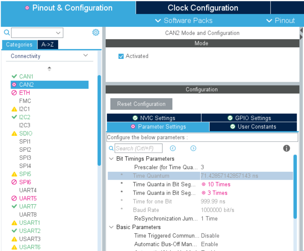
The common problem of rate configuration is that if the rate is directly configured in the cube, the infinite circular decimal is not allowed in the new cube. If the main board is 168Mhz, it cannot be configured to 1Mhz in the cube, as shown in the figure below. Therefore, you can only find the void MX after generating the code_ CAN1_ Init (void) initializes the function to modify the rate.
2. Pin
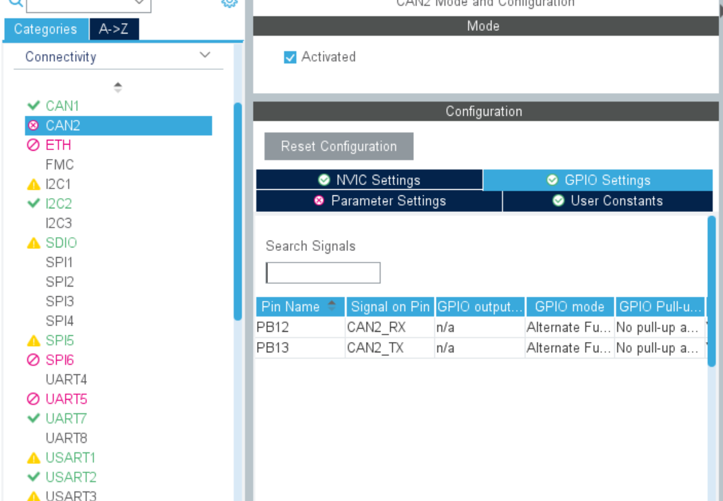
The pins of can line include TX pin and RX pin, which must be configured properly, otherwise the initialization of can line cannot pass normally.
The method here is to find the schematic diagram of the board you use and find out which pins of the can line are. Here we still need to mention the cube. Most cubes automatically generate two pins, but please note that the pins here are not completely correct, so it's best to find the pins for configuration.
3. Interrupt callback
The communication of can line is also through the interrupt callback function. The code generated by cube can be in stm32fxxx_it.c file, for example, Tx interrupt callback of can1 and Rx0 interrupt callback,
void CAN1_TX_IRQHandler(void)
{
  /* USER CODE BEGIN CAN1_TX_IRQn 0 */

  /* USER CODE END CAN1_TX_IRQn 0 */
  HAL_CAN_IRQHandler(&hcan1);
  /* USER CODE BEGIN CAN1_TX_IRQn 1 */

  /* USER CODE END CAN1_TX_IRQn 1 */
}

/**
  * @brief This function handles CAN1 RX0 interrupts.
  */
void CAN1_RX0_IRQHandler(void)
{
  /* USER CODE BEGIN CAN1_RX0_IRQn 0 */

  /* USER CODE END CAN1_RX0_IRQn 0 */
  HAL_CAN_IRQHandler(&hcan1);
  /* USER CODE BEGIN CAN1_RX0_IRQn 1 */

  /* USER CODE END CAN1_RX0_IRQn 1 */
}
The function calling can line output is
HAL_CAN_AddTxMessage(hcanx, &TxMessage, TxData, &pTxMailbox);
The function received by can line is
void HAL_CAN_RxFifo0MsgPendingCallback(CAN_HandleTypeDef *hcan);
void HAL_CAN_RxFifo1MsgPendingCallback(CAN_HandleTypeDef *hcan);
The difference between the two receiving functions here is the different fifo buffers used,
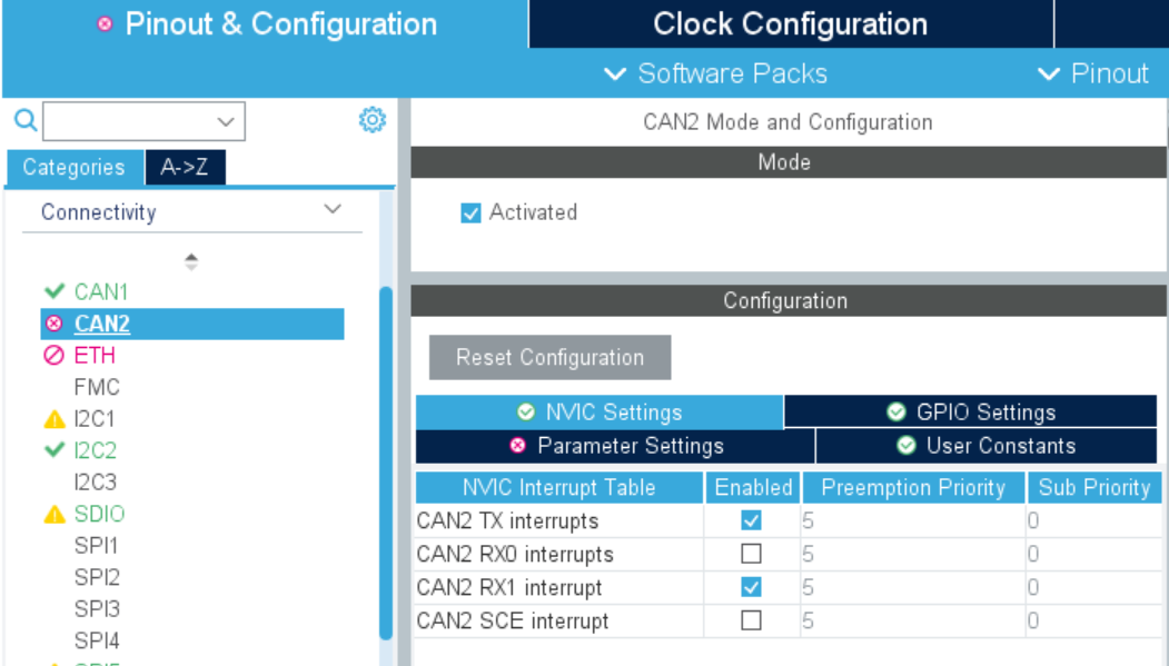
Generally speaking, we let can1 use FIFO0 and can2 use FIFO1. There is a problem here. There is only one TX in the interrupt callback, but there are two rxs, one RX0 and the other RX1. The difference between 0 and 1 here is caused by the different use of buffers,
Therefore, for normal use, use FIFO0 to enable RX0 interrupt and FIFO1 to enable RX1 interrupt.
summary
This paper mainly summarizes the can line problems I encountered in the development of stm32, and looks forward to supplement and progress together.