Recently, tubing recommended the tutorial of Interior Mapping, which is very interesting. I found that all kinds of materials are scattered
So I collected and learned some materials everywhere. With this article summary, we can study together
1 background introduction - false window
What is Interior Mapping? Let's start with the window in the game
This is a furniture store in GTA IV
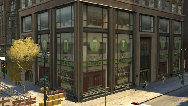
If we take a closer look, we can find
- It looks good in art, and its visual colors and collocations are also very interesting. It is suitable for the theme and location of the furniture store, and the atmosphere is also very good... Just something is wrong.
- Through the window, we can only see a picture of the store, which is directly photographed on the window glass like a sticker on the glass.
There is no perspective difference between windows on different parts of the corner.
Even if the camera is at an angle to the wall, the internal view is always facing the front.
This lack of perspective greatly weakens the sense of atmosphere.
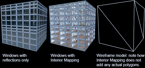
The easiest way to make the room appear behind the window is to fill each room with an actual model.
This is applicable for small-scale scenes, but it is obviously impractical for large-scale games.
The consumption of triangular patches of these internal models is too exaggerated for large-scale games, especially when we play, we often only occasionally see a small part of a few rooms.
So, how to balance performance and effect? The answer, as mentioned at the beginning, is the little Trick on Shader
2 how to simulate windows?
2.1 general - Parallax Mapping
Shader takes geometric information as input and outputs color in one operation. Our only concern is that the final output color looks correct in the scene, and what happens in the middle is not important.
So if we can offset the output color to make it look like the input geometric model, we will achieve our goal.
If the output offset is not uniform, the rendered image can look as if it has been skewed, distorted or deformed to some extent.
How? We will immediately think of a general offset technology in this regard, Parallax Mapping.
- The following figure is a typical example of using parallax effect in real life, similar to a projection
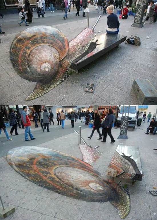
This is before Learning notes on parallax mapping on learnopungl.
When using parallax mapping, we input texture coordinates and offset them according to the observer angle and the "depth" value of each pixel. By determining the point where the camera ray intersects the surface height, we can create a 2D image equivalent to 3D projection.
Can parallax mapping achieve indoor effect? Although it seems very suitable for our needs, that is, the need to represent 3D effects in 2D plane.
However, as a general solution, parallax mapping does not seem to work well when it is used in specific situations for indoor scenes.
- Parallax mapping works best on smoother height maps.
If the height difference of texture elements on the height map is too large, it will cause strange visual distortion. There are some alternative methods to solve this problem (such as "steep parallax mapping"), but the alternative methods are basically iterative, and will produce a stepped effect with the increase of the ratio of depth to the number of iterations.
In addition to the large consumption of iteration times, we also found that the volume of the window is inside, and parallax usually simulates the concave convex degree of the surface rather than the internal simulation.
When a generic solution fails, we need to consider simple, specific solutions that may be satisfied.
2.2 specific - Interior Mapping
Specific analysis of specific problems, how do we offset the shader of the window?
In our case, we want to insert a rectangular room into our window.
The versatility of parallax mapping means that iterative numerical methods must be used, because there is no analytical method to determine where our camera rays intersect the surface height.
If we only limit the problem to the room with rectangular box, we just need to map the intersection points in the room volume to the texture, and then output the correct color.
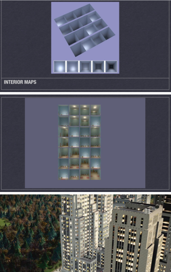
Joost van Dongen Presented a paper at the 2008 CGI conference: Interior Mapping: A new technique for rendering realistic buildings , as the origin of the technology (this is provided by the author) demo).
And before Volume paint shader In this paper, Interior Mapping considers that the building itself does not contain any additional geometry, and the internal volume is only false and exists in the shader.
It divides the mesh of the building grid into many "rooms", and raycast the texture pixels of the windows in each room.
Samples a set of room textures using coordinates at the intersection of camera rays and the room box.
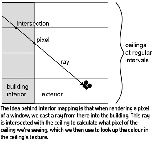
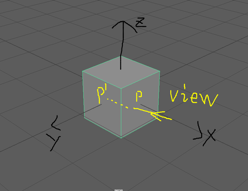
- Take a box room as an example. A room has six sides, four walls, ceiling and floor, but we just need to consider the three sides we can see.
Calculate the intersection of the ray and each of the three planes, such as p ', and then we use the intersection p' as the texture coordinate to find the color of pixel P.
Thus, similar to parallax mapping, it offsets the coordinates of the input texture and provides a projection of the wall, ceiling and floor textures for each hidden "room box".
Without increasing the complexity of other geometric shapes and materials, it better represents the internal space.
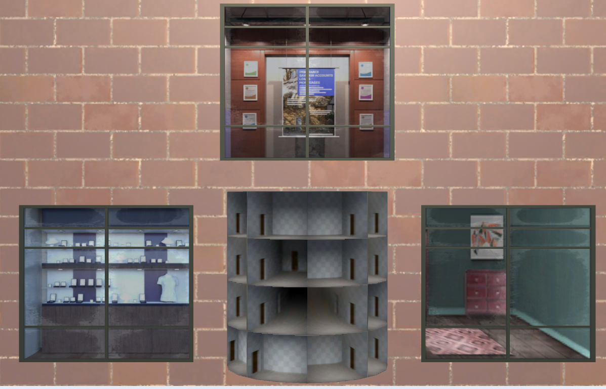
Its technology is widely used in today's games, such as the "false" rooms in the following windows
-
In Marvel spider man, the character climbs a wall on a building Demo video It seems that the interior of the building can be seen through the glass
But in fact, you can find strange places around the corner
-
This is another one from Marvel spider man Demo video It can also be found that the room does not actually exist in the geometry. The glass at the corner has a door, but there should obviously be a window
-
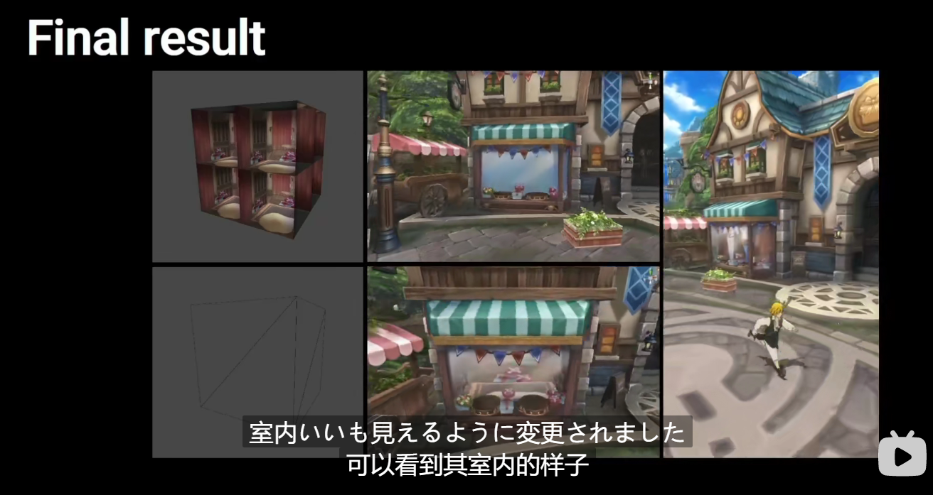
stay Technology sharing of "seven crimes" In, the speaker shared a technology called fake interior, which is used by technicians to simulate indoor effects
-
In the watchman, the player found A magical window
There are many examples in the game. Although all these show that the rooms they see through the window are forged, the application of Interior Mapping makes them completely correct in perspective and have real depth.
3 implementation mode
3.1 object space / tangent space
The object in the room or the world is defined in the paper.
It's really easy to use directly, but it doesn't do well on buildings with sloping or curved walls
Rooms are limited by building geometry, which may lead to unevenness or room truncation, as shown in the following figure, the example in the paper author's demo
In reality, rooms are almost always aligned with the outside of the building.
So we prefer to align all the rooms with the mesh, then squeeze inward and extend to the center of the building.
In order to do this, we can calculate and find an alternative coordinate system, which is consistent with our surface, that is, we can do raycast calculation in tangent space.
Even if world space is curved, tangent space is always axis aligned.
After tangent space calculation, our room can change with the curvature of the building, and always has a whole wall parallel to the outside of the building.
3.2 room mapping
For the mapping of rooms, separate textures are required for walls, floors and ceilings.
Although it works, it is difficult to operate. To keep the three textures synchronized, it is difficult to put the textures of multiple rooms together.
So people also put forward some other methods
3.2.1 cube map - seven crimes
Where's Zoe J Wood "Interior Mapping Meets Escher" The cube map is used instead of the original map.
stay Technology sharing of "seven crimes" They also use this method. They use cubeMap indoors, then add a map of the window, and provide depth to adjust the depth of field
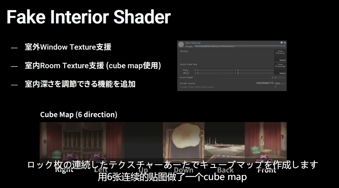
However, cube mapping also means that it is almost impossible for people to manually fine tune the mapping, which is not friendly for artists to build a variety of internal mapping assets.
3.2.2 pre projected 2D map - simulated city 5
Andrew Willmott, the developer of simulated city 5 "From AAA to Indie: Graphics R&D" In their speech, they mentioned that they used the pre projected internal texture for the internal map in simulated city 5, which is PPT at that time.
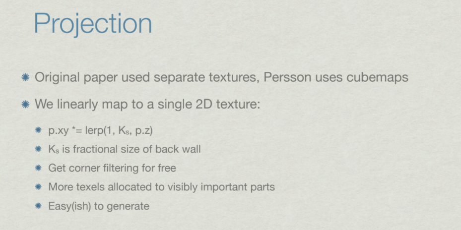
This method is relatively good, highly creative, easy to use, and the display result is only a little worse than the complete cube map.
- Because the mapping is based on a projection image, the most perfect effect can be obtained only from the original rendering angle of the image.
Changing to other angles or changing the depth mapping at will will cause some slight distortion and distortion
Moreover, it can build a large number of indoor atlas on the basis of each building and select them randomly, so that only one texture resource can be used, and the building can maintain the internal scene style with random changes.
It can only be said that and cubemap have their own advantages and disadvantages
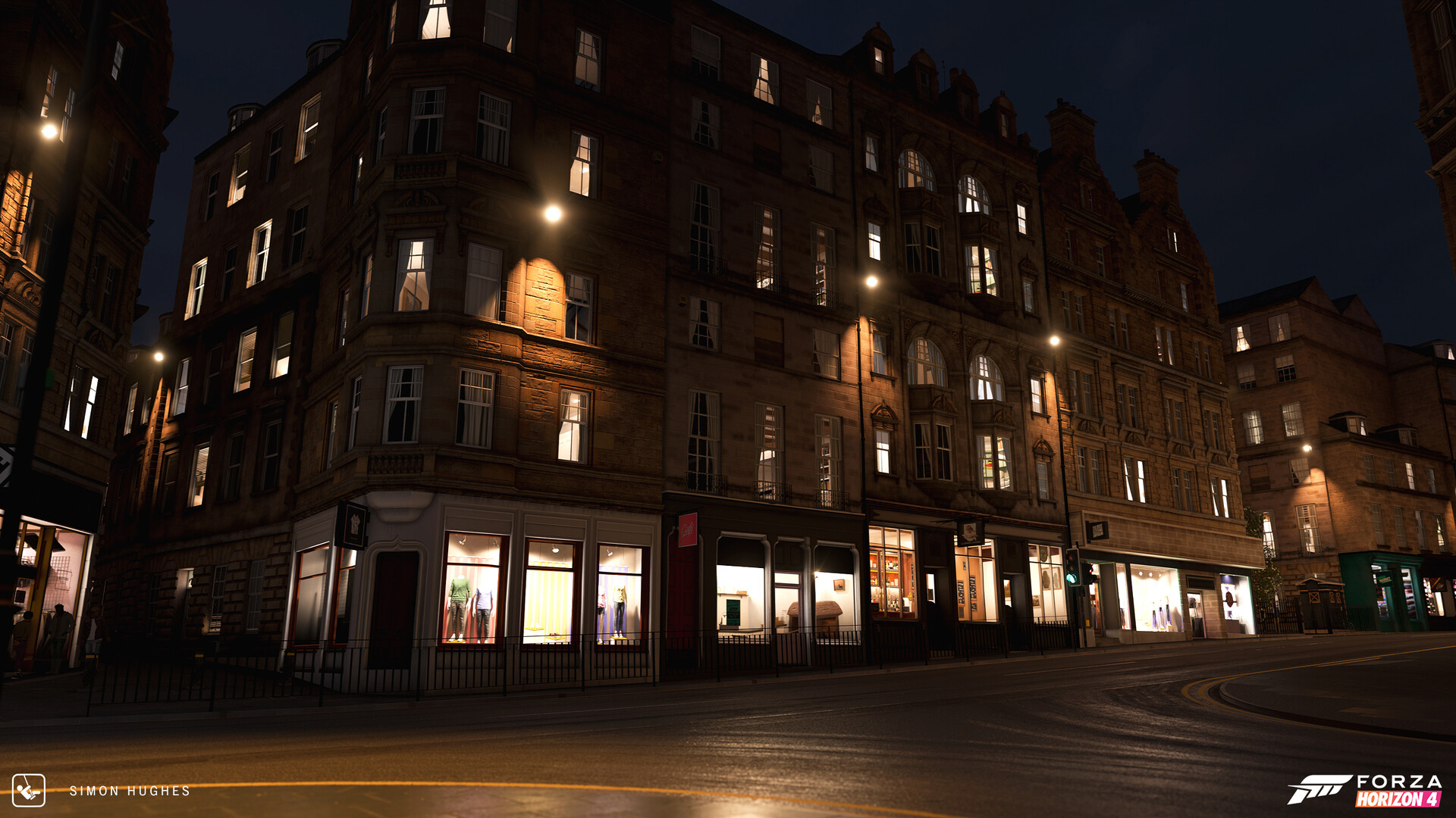
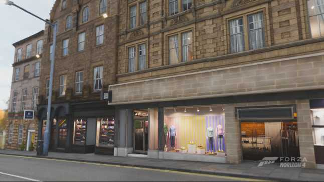
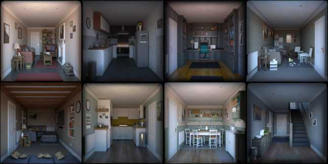
3.2.3 pre projected 2D map - Extreme Racing: Horizon 4
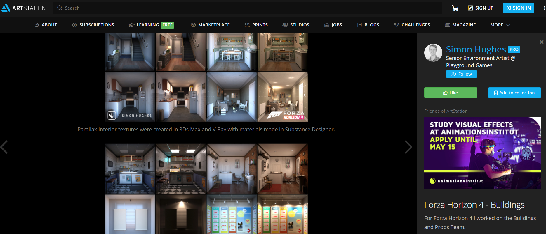
Similarly, Gareth Harwood, technical art director of Playground Games An interview with The Gamasutra Deep Dives It is also mentioned in "extreme racing: Horizon 4" that pre projection 2D mapping is also used to realize indoor mapping and make street view windows
The interview mentioned several important parts:
Three layers of texture are formed in the window + window frame + interior; Use of atlas; Texture switching between night and day; Small angle processing; Precautions for internal texture modeling; Regular placement of internal texture; Performance optimization
Here are some excerpts from the interview, which are of reference significance. After translation, you can understand it
- Creating a realistic world has always been an advantage of the extreme race: Horizon Series, and one aspect of our goal is to add interior decoration to buildings.
- In extreme racing: Horizon 4, we know that Edinburgh is so dense and detailed that the internal space of physical modeling will exceed our budget, so we studied another technology called parallax texture.
This gives us a huge advantage in creating an interior because it is baked into a texture without being limited by the number of polygons or material complexity.
Since rendering these objects is cheaper than creating geometry, we can have more interiors in the game.
In the past, due to budget problems, we may need to close the curtains or darken the windows. Now we have a complete parallax interior.
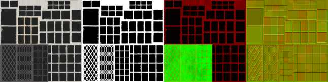
- The parallax interior material consists of three layers, which the artist can select independently for each window.
Because each layer has several different options, even if only a small amount of Atlas texture is used, this provides hundreds of possible visual effects for each window. - The first floor is very simple, including window frames and glass.
This adds nuances, such as the details of the window glass or the window frames on the windows, which are particularly prominent in older British buildings. The layer has diffuse reflection, alpha, roughness, metallicity and normals.
Normals increase the true change in the glass reflection angle by including changes in each pane, which is more obvious in our Antique panes.
- The second floor is curtains or shutters.
These have diffuse and Alpha, but also have a transmissive texture that is used to show the thickness of the curtains at night.
We have thick curtains that prevent light from passing through, translucent shutters, and even gorgeous curtains. The curtains made of lace allow some light to pass through. - The last layer is where the shader produces magical effects, because it simulates the planar texture inside 3D.
First, the interior is modeled with a 3D model using a unified scale, and then rendered into a unique texture format supported by the indoor mapping shader.
Like other layers, we created an atlas that contains up to eight different interior decorations of the same style to reduce drawing calls.
We have some atlases of rural areas, which are shared among rural families, atlases of urban houses, and some commercial atlases in our shops, restaurants and typical English bars.
We also have two main internal depths.
One is used for standard room and the other is used for shallow window display.
When the artist selects the desired properties for each window of the atlas, he can set the required properties for each window.
- The shader calculates the angle you see in the room and adjusts the UV s so that you can only see the interior area visible from your perspective.
This technology has some limitations that we need to solve. - First, the trick of the shader becomes obvious at a very shallow angle.
In these edge cases, we added the natural Fresnel effect of glass to show more reflective images than indoors.
Second, as the angle increases, the details in the center of the room begin to bend. We reduce this by attracting interest to walls and corners and darkening the floor.
As in real life, parallax effect can be achieved by converging lines to a certain point.
In our images, we use parallel lines as much as possible to play the game: tiles, bookshelves, wooden floors and patterned wallpaper.
Each internal texture also has an auxiliary light texture at night, and the advantage of baking the texture again is that you can use as much light as you need, because they will eventually be merged into one texture.
We have on and off time for each building to increase the change when the lights are on.
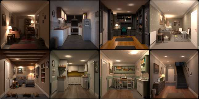
- Artists are free to choose any type of window, curtain and interior combination they like.
But they follow some simple rules: bedrooms usually appear on higher floors. We don't repeat the same room on each window, and we don't put an ascending top floor on the stairs.
We also studied the feasibility of each room.
For example, we can't have a small two bedroom hut with ten or more windows that can see different rooms, so the artist set up windows that can see different parts of the same room. - Finally, for performance reasons; When players leave the building, we need to reduce not only the complexity of the mesh, but also the complexity of shaders and materials.
To this end, we dilute the parallax effect and replace the window with a flat image, which is a picture with window, curtain and interior.
This happens when the window is small on the screen and the player doesn't notice.
For the high-definition pictures used in extreme racing: Horizon 4, you can go to Producer's A station this link download
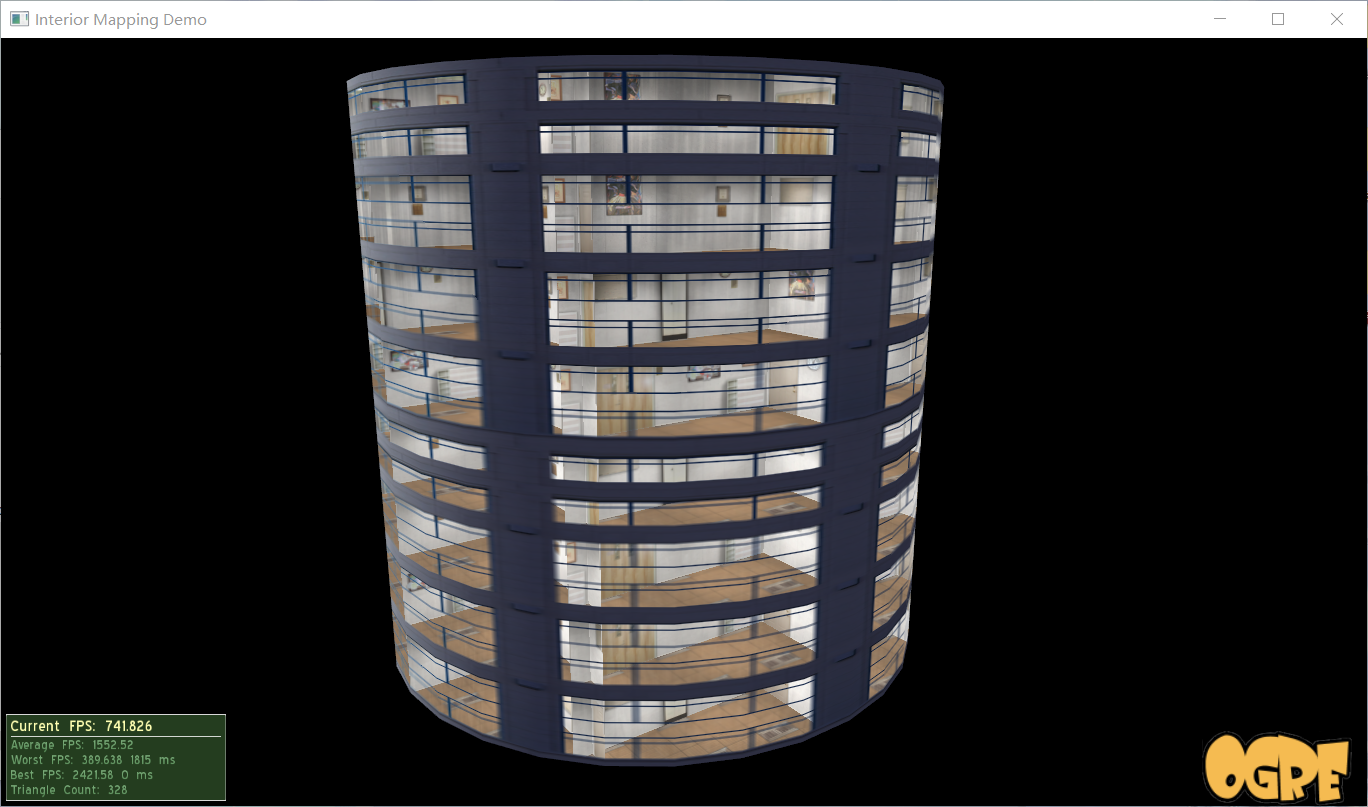
4 try it
In terms of implementation, the model and some maps in the free resource Fake Interiors FREE in Unity mall are borrowed, and the shader structure and Discussion of Unity Forum,colin greatly realizes
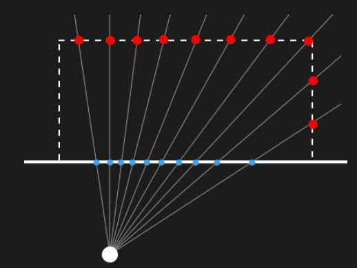
The core idea is how to sample virtual rooms
Because we are running the shader in the window (facing us), which point of the virtual room box in the back will a light from the window hit?
That is, the intersection of light and AABB (axis aligned bounding box)
Let's take 2D as an example, for a given light
We can find the intersection with the vertical and horizontal planes respectively, that is, we can find the intersection on the X-axis and Y-axis respectively
We take all entry times(
t
m
i
n
t_{min}
max in tmin), time to go out
t
m
a
x
t_{max}
min in tmax +,
So we got the way in and out of the bounding box
t
t
Value of t
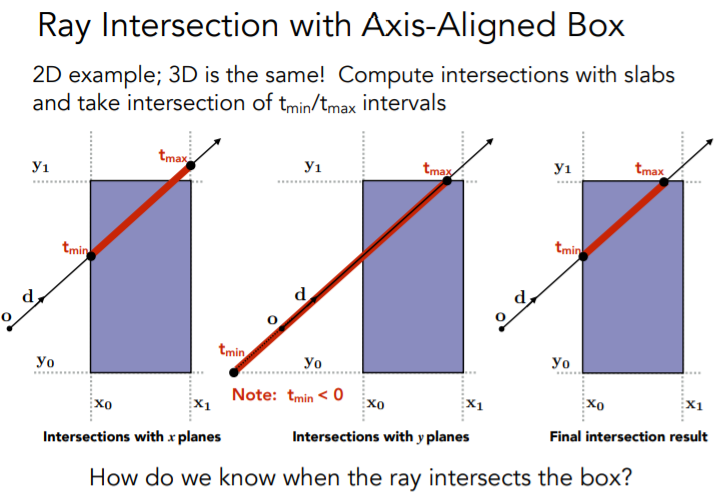
The same is true for the processing of 3D boxes. The general solution is as follows
Suppose the starting point is a certain point, which is
P
P
Point P, the direction vector of the line of sight is
d
⃗
\vec{d}
d
With "time"
t
t
If t is the independent variable, we can get the ray
L
(
t
)
=
P
+
t
d
⃗
L(t)=P+t\vec{d}
L(t)=P+td
Align it with the axis bounding box
(
B
m
i
n
,
B
m
a
x
)
(B_{min},B_{max})
(Bmin, Bmax) do intersection test

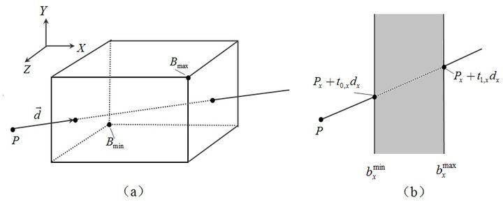
A bounding box has six rectangular faces. If two rectangles parallel to each other are regarded as a plate, the problem is transformed into finding the intersection of rays and three plates perpendicular to each other
Taking the X-axis as an example (as shown in Figure b), we can get the entry time on the X-axis
t
0
x
t_0x
t0 # x and
t
1
x
t_1x
t1x


The Y and Z axes are the same, and then in XYZ
t
0
t_0
Take the maximum in t0 , to get the entry point, which is in XYZ
t
1
t_1
Take the minimum of t1 , and you can get the point
In the specific application, make minor adjustments as needed. You can see the implementation process of the following code
In addition, the intersection algorithm between rays and various shapes can be seen This page
4.1 cube mapping
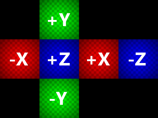
First, implement a cube mapping method
For example, use such a cubemap
4.1.1 method of objectspace
Let's start with the method implemented in object space, regardless of tangent space,
To avoid distracting attention, first show only the main idea of the shader
v2f vert(appdata v)
{
	v2f o;
	o.pos = UnityObjectToClipPos(v.vertex);
	// slight scaling adjustment to work around "noisy wall"
	// when frac() returns a 0 on surface
	o.uvw = v.vertex * _RoomCube_ST.xyx * 0.999 + _RoomCube_ST.zwz;

	// get object space camera vector
	float4 objCam = mul(unity_WorldToObject, float4(_WorldSpaceCameraPos, 1.0));
	o.viewDir = v.vertex.xyz - objCam.xyz;

	// adjust for tiling
	o.viewDir *= _RoomCube_ST.xyx;
	return o;
}
- o.UVW is the position of the pixel in model space, which we will use to sample later
Here, with the influence of tilling, the parameter of ST is added, and in order to avoid extreme values, multiply it by 0.999 and adjust the UVW value
Calculate the line of sight direction according to the camera and current position (i.e. in formula derivation) d ⃗ \vec{d} d ) - The camera position is always above the plane, and you can see the front of the plane (the back is eliminated)
fixed4 frag(v2f i) : SV_Target
{
	// room uvws
	float3 roomUVW = frac(i.uvw);

	// raytrace box from object view dir
	// transform object space uvw( min max corner = (0,0,0) & (+1,+1,+1))
	// to normalized box space(min max corner = (-1,-1,-1) & (+1,+1,+1))
	float3 pos = roomUVW * 2.0 - 1.0;

	// for axis aligned box Intersection,we need to know the zoom level
	float3 id = 1.0 / i.viewDir;

	// k means normalized box space depth hit per x/y/z plane seperated
	// (we dont care about near hit result here, we only want far hit result)
	float3 k = abs(id) - pos * id;
	// kmin = normalized box space real hit ray length
	float kMin = min(min(k.x, k.y), k.z);
	// normalized box Space real hit pos = rayOrigin + kmin * rayDir.
	pos += kMin * i.viewDir;

	// randomly flip & rotate cube map for some variety
	float3 flooredUV = floor(i.uvw);
	float3 r = rand3(flooredUV.x + flooredUV.y + flooredUV.z);
	float2 cubeflip = floor(r.xy * 2.0) * 2.0 - 1.0;
	pos.xz *= cubeflip;
	pos.xz = r.z > 0.5 ? pos.xz : pos.zx;


	// sample room cube map
	fixed4 room = texCUBE(_RoomCube, pos.xyz);
	return fixed4(room.rgb, 1.0);
}
- roomUVW = frac(i.uvw); Truncate the decimal part as the UV value of the sample
- Standardize the virtual room. After * 2-1, the original UVW of (0,0,0) ~ (+ 1, + 1, + 1) changes to (- 1, - 1, - 1) ~ (+ 1, + 1, + 1)
- Recall the formula here
Because we are running the shader on the surface of the window, the P P P is the standardized in the code P o s Pos Pos
We just need to consider the point where the light goes out, that is, we just need to know t 1 t_1 t1 (in code) k k k) What is the value of
After standardization, b m a x = ( 1 , 1 , 1 ) b_{max}=(1,1,1) bmax = (1,1,1), so there is no need to multiply; and d ⃗ \vec{d} d namely v i e w D i r viewDir viewDir - Because the calculation method of the three axes is the same, we can get the value in the code for the output point
float kMin = min(min(k.x, k.y), k.z);
Then, according to the ray formula, we can get the position of the intersection point (some random rotation and selection operations are done later, which can be ignored), and then we can use it to sample the CubeMap
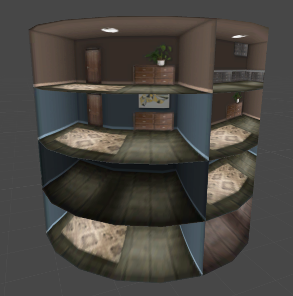
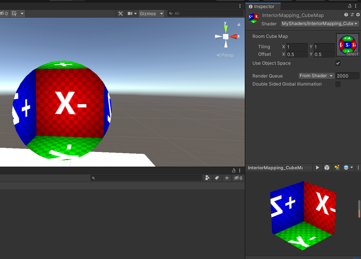
It can be found that the box can be seen inside
However, for the ObjectSpace method, the internal rooms can only be aligned strictly according to the axis, which is very strange on the surface
4.1.2 TangentSpace method
In order to make box perform well on the surface, we find the intersection in tangent space, and the code is almost the same as a whole
v2f vert(appdata v)
{
	v2f o;
	o.pos = UnityObjectToClipPos(v.vertex);
	// uvs
	o.uv = TRANSFORM_TEX(v.uv, _RoomCube);

	// get tangent space camera vector
	float4 objCam = mul(unity_WorldToObject, float4(_WorldSpaceCameraPos, 1.0));
	float3 viewDir = v.vertex.xyz - objCam.xyz;
	float tangentSign = v.tangent.w * unity_WorldTransformParams.w;
	float3 bitangent = cross(v.normal.xyz, v.tangent.xyz) * tangentSign;
	o.viewDir = float3(
		dot(viewDir, v.tangent.xyz),
		dot(viewDir, bitangent),
		dot(viewDir, v.normal)
		);

	// adjust for tiling
	o.viewDir *= _RoomCube_ST.xyx;
	return o;
}
- TRANSFORM_TEX method is to calculate the uv of the model vertex and the two variables of Tiling and Offset to calculate the uv for actual display
- For the transformation of tangent space, just multiply the line of sight by TBN matrix
fixed4 frag(v2f i) : SV_Target
{
	// room uvs
	float2 roomUV = frac(i.uv);

	// raytrace box from tangent view dir
	float3 pos = float3(roomUV * 2.0 - 1.0, 1.0);
	float3 id = 1.0 / i.viewDir;
	float3 k = abs(id) - pos * id;
	float kMin = min(min(k.x, k.y), k.z);
	pos += kMin * i.viewDir;

	// randomly flip & rotate cube map for some variety
	float2 flooredUV = floor(i.uv);
	float3 r = rand3(flooredUV.x + 1.0 + flooredUV.y * (flooredUV.x + 1));
	float2 cubeflip = floor(r.xy * 2.0) * 2.0 - 1.0;
	pos.xz *= cubeflip;
	pos.xz = r.z > 0.5 ? pos.xz : pos.zx;
#endif

	// sample room cube map
	fixed4 room = texCUBE(_RoomCube, pos.xyz);
	return fixed4(room.rgb, 1.0);
}
- Slice shaders are similar, basically the same
When defining pos, let Z=1 (Z is N in TBN) and sample inward
float3 pos = float3(roomUV * 2.0 - 1.0, 1.0);
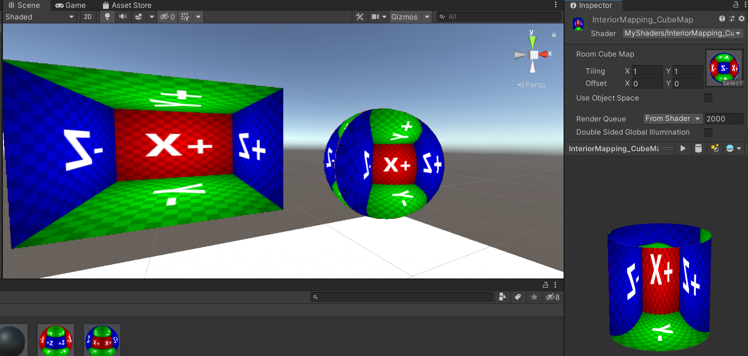
Get the effect and perform well on the surface
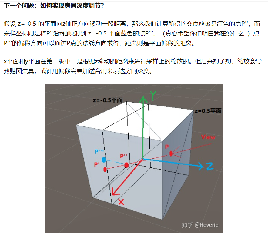
4.1.3 depth
How to achieve depth?
We specify a depth value, and then add the code of depth mapping in front of the slice shader. We multiply the depth by the Z of the line of sight
// Specify depth manually
fixed farFrac = _RoomDepth;

//remap [0,1] to [+inf,0]
//->if input _RoomDepth = 0    -> depthScale = 0      (inf depth room)
//->if input _RoomDepth = 0.5  -> depthScale = 1
//->if input _RoomDepth = 1    -> depthScale = +inf   (0 volume room)
float depthScale = 1.0 / (1.0 - farFrac) - 1.0;
i.viewDir.z *= depthScale;
If we enlarge the magnification of line of sight Z on the original basis, that is, the line of sight vector moves further away, and the sampling seems to be deeper
The above method is to scale the sampling according to the distance of z movement, which will lead to the distortion of the surrounding map
You can also use offset to express the depth of the room, that is, the whole moves back and forth, so the offset depth is very limited, which can only be the depth of the box
Can see This great achievement
4.1.4 code
That's how it's integrated
// Upgrade NOTE: replaced 'mul(UNITY_MATRIX_MVP,*)' with 'UnityObjectToClipPos(*)'

Shader "MyShaders/InteriorMapping_CubeMap"
{
	Properties
	{
		_RoomCube("Room Cube Map", Cube) = "white" {}
		[Toggle(_USEOBJECTSPACE)] _UseObjectSpace("Use Object Space", Float) = 0.0
		_RoomDepth("Room Depth",range(0.001,0.999)) = 0.5
	}
	SubShader
	{
		Tags { "RenderType" = "Opaque" }
		LOD 100

		Pass
		{
			CGPROGRAM
			#pragma vertex vert
			#pragma fragment frag

			#pragma shader_feature _USEOBJECTSPACE

			#include "UnityCG.cginc"

			struct appdata
			{
				float4 vertex : POSITION;
				float2 uv : TEXCOORD0;
				float3 normal : NORMAL;
				float4 tangent : TANGENT;
			};

			struct v2f
			{
				float4 pos : SV_POSITION;
			#ifdef _USEOBJECTSPACE
				float3 uvw : TEXCOORD0;
			#else
				float2 uv : TEXCOORD0;
			#endif
				float3 viewDir : TEXCOORD1;
			};

			samplerCUBE _RoomCube;
			float4 _RoomCube_ST;
			float _RoomDepth;
			// Pseudorandom pseudorandom
			float3 rand3(float co) {
				return frac(sin(co * float3(12.9898,78.233,43.2316)) * 43758.5453);
			}

			v2f vert(appdata v)
			{
				v2f o;
				o.pos = UnityObjectToClipPos(v.vertex);
			#ifdef _USEOBJECTSPACE
				// slight scaling adjustment to work around "noisy wall" when frac() returns a 0 on surface
				o.uvw = v.vertex * _RoomCube_ST.xyx * 0.999 + _RoomCube_ST.zwz;

				// get object space camera vector
				float4 objCam = mul(unity_WorldToObject, float4(_WorldSpaceCameraPos, 1.0));
				o.viewDir = v.vertex.xyz - objCam.xyz;

				// adjust for tiling
				o.viewDir *= _RoomCube_ST.xyx;
			#else
				// uvs
				o.uv = TRANSFORM_TEX(v.uv, _RoomCube);

				// get tangent space camera vector
				float4 objCam = mul(unity_WorldToObject, float4(_WorldSpaceCameraPos, 1.0));
				float3 viewDir = v.vertex.xyz - objCam.xyz;
				float tangentSign = v.tangent.w * unity_WorldTransformParams.w;
				float3 bitangent = cross(v.normal.xyz, v.tangent.xyz) * tangentSign;
				o.viewDir = float3(
					dot(viewDir, v.tangent.xyz),
					dot(viewDir, bitangent),
					dot(viewDir, v.normal)
					);

				// adjust for tiling
				o.viewDir *= _RoomCube_ST.xyx;
			#endif
				return o;
			}

			fixed4 frag(v2f i) : SV_Target
			{

				// Specify depth manually
				fixed farFrac = _RoomDepth;

				//remap [0,1] to [+inf,0]
				//->if input _RoomDepth = 0    -> depthScale = 0      (inf depth room)
				//->if input _RoomDepth = 0.5  -> depthScale = 1
				//->if input _RoomDepth = 1    -> depthScale = +inf   (0 volume room)
				float depthScale = 1.0 / (1.0 - farFrac) - 1.0;
				i.viewDir.z *= depthScale;
			#ifdef _USEOBJECTSPACE
				// room uvws
				float3 roomUVW = frac(i.uvw);

				// raytrace box from object view dir
				// transform object space uvw( min max corner = (0,0,0) & (+1,+1,+1))
				// to normalized box space(min max corner = (-1,-1,-1) & (+1,+1,+1))
				float3 pos = roomUVW * 2.0 - 1.0;

				// for axis aligned box Intersection,we need to know the zoom level
				float3 id = 1.0 / i.viewDir;

				// k means normalized box space depth hit per x/y/z plane seperated
				// (we dont care about near hit result here, we only want far hit result)
				float3 k = abs(id) - pos * id;
				// kmin = normalized box space real hit ray length
				float kMin = min(min(k.x, k.y), k.z);
				// normalized box Space real hit pos = rayOrigin + kmin * rayDir.
				pos += kMin * i.viewDir;

				// randomly flip & rotate cube map for some variety
				float3 flooredUV = floor(i.uvw);
				float3 r = rand3(flooredUV.x + flooredUV.y + flooredUV.z);
				float2 cubeflip = floor(r.xy * 2.0) * 2.0 - 1.0;
				pos.xz *= cubeflip;
				pos.xz = r.z > 0.5 ? pos.xz : pos.zx;
			#else
				// room uvs
				float2 roomUV = frac(i.uv);

				// raytrace box from tangent view dir
				float3 pos = float3(roomUV * 2.0 - 1.0, 1.0);
				float3 id = 1.0 / i.viewDir;
				float3 k = abs(id) - pos * id;
				float kMin = min(min(k.x, k.y), k.z);
				pos += kMin * i.viewDir;

				// randomly flip & rotate cube map for some variety
				float2 flooredUV = floor(i.uv);
				float3 r = rand3(flooredUV.x + 1.0 + flooredUV.y * (flooredUV.x + 1));
				float2 cubeflip = floor(r.xy * 2.0) * 2.0 - 1.0;
				pos.xz *= cubeflip;
				pos.xz = r.z > 0.5 ? pos.xz : pos.zx;
			#endif

				// sample room cube map
				fixed4 room = texCUBE(_RoomCube, pos.xyz);
				return fixed4(room.rgb, 1.0);
			}
            ENDCG
        }
    }
}
4.2 pre projected 2d map
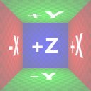
For cube shaped rooms, if the size of the back wall is 1 / 2 of the visible ceramic tile
At this time, if they are rendered, use a camera with a horizontal FOV of 53.13 degrees from the opening back.
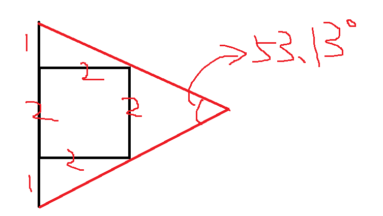
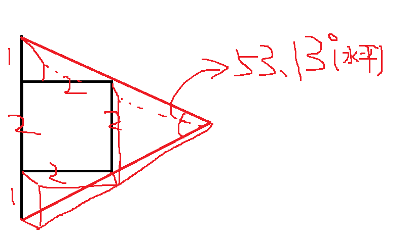
We can then specify the depth unit in this case as the standard depth, that is_ RoomDepth = 0.5 → depthScale = 1
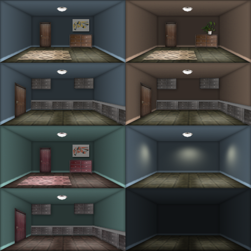
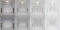
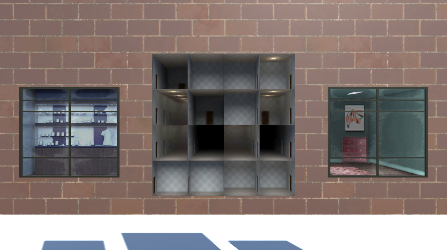
For example, the following figure is rendered in this case
The room depth can be stored in the alpha channel of the atlas texture (the standard depth is 128 for the alpha channel)
You can also make many atlas
Of course, you can manually adjust the depth regardless of the alpha channel. The code of these two specifying methods will explain
You can also go Horizon 4 producer's A-stop link Download Atlas
Our overall idea remains unchanged. First, find the intersection point in the axis aligned bounding box, and then map the intersection point of the three-dimensional space originally to sample the cubemap to the UV of the 2d image, and sample the pre projected 2d image
4.2.1 realization
Vertex shader functions as before, around tangent space
v2f vert(appdata v)
{
	v2f o;
	o.pos = UnityObjectToClipPos(v.vertex);
	o.uv = TRANSFORM_TEX(v.uv, _RoomTex);

	// get tangent space camera vector
	float4 objCam = mul(unity_WorldToObject, float4(_WorldSpaceCameraPos, 1.0));
	float3 viewDir = v.vertex.xyz - objCam.xyz;
	float tangentSign = v.tangent.w * unity_WorldTransformParams.w;
	float3 bitangent = cross(v.normal.xyz, v.tangent.xyz) * tangentSign;
	o.tangentViewDir = float3(
		dot(viewDir, v.tangent.xyz),
		dot(viewDir, bitangent),
		dot(viewDir, v.normal)
		);
	o.tangentViewDir *= _RoomTex_ST.xyx;
	return o;
}
The chip shader code is as follows
// psuedo random
float2 rand2(float co) {
	return frac(sin(co * float2(12.9898,78.233)) * 43758.5453);
}

fixed4 frag(v2f i) : SV_Target
{
	// room uvs
	float2 roomUV = frac(i.uv);
	float2 roomIndexUV = floor(i.uv);

	// randomize the room
	float2 n = floor(rand2(roomIndexUV.x + roomIndexUV.y * (roomIndexUV.x + 1)) * _Rooms.xy);
	//float2 n = floor(_Rooms.xy);
	roomIndexUV += n;

	// get room depth from room atlas alpha
	// fixed farFrac = tex2D(_RoomTex, (roomIndexUV + 0.5) / _Rooms).a;

	// Specify depth manually
	fixed farFrac = _RoomDepth;

	//remap [0,1] to [+inf,0]
	//->if input _RoomDepth = 0    -> depthScale = 0      (inf depth room)
	//->if input _RoomDepth = 0.5  -> depthScale = 1
	//->if input _RoomDepth = 1    -> depthScale = +inf   (0 volume room)
	float depthScale = 1.0 / (1.0 - farFrac) - 1.0;

	// raytrace box from view dir
	// normalized box space's ray start pos is on trinagle surface, where z = -1
	float3 pos = float3(roomUV * 2 - 1, -1);
	// transform input ray dir from tangent space to normalized box space
	i.tangentViewDir.z *= -depthScale;
	float3 id = 1.0 / i.tangentViewDir;
	float3 k = abs(id) - pos * id;
	float kMin = min(min(k.x, k.y), k.z);
	pos += kMin * i.tangentViewDir;

	// remap from [-1,1] to [0,1] room depth
	float interp = pos.z * 0.5 + 0.5;

	// account for perspective in "room" textures
	// assumes camera with an fov of 53.13 degrees (atan(0.5))
	// visual result = transform nonlinear depth back to linear
	float realZ = saturate(interp) / depthScale + 1;
	interp = 1.0 - (1.0 / realZ);
	interp *= depthScale + 1.0;

	// iterpolate from wall back to near wall
	float2 interiorUV = pos.xy * lerp(1.0, farFrac, interp);
	interiorUV = interiorUV * 0.5 + 0.5;

	// sample room atlas texture
	fixed4 room = tex2D(_RoomTex, (roomIndexUV + interiorUV.xy) / _Rooms);
	return fixed4(room.rgb, 1.0);
}
- It is normal to select room UV s and random parts
The depth value can be obtained from the alpha channel of the graph or can be specified manually
When depthScale is specified, the depth input of 0 ~ 1 is mapped to 0 ~ +inf - The code to get the depth from the map is the short section of the annotation
// fixed farFrac = tex2D(_RoomTex, (roomIndexUV + 0.5) / _Rooms).a; - Because of the elimination of the back, the camera that can be seen is always on the front of the plane, so the line of sight is always pointing in the plane
We don't need to adjust the tangent of the top of the cuboid to be 1, so we don't need to specify the tangent of the cuboid to be 1 in the space
Now specify the Z value of pos as - 1
float3 pos = float3(roomUV * 2 - 1, -1); The plane is located on the bottom of the standardized cube
We're going to put i.tangentviewdir z *= -depthScale;, Reverse the Z of your line of sight - So why specify Z of pos as - 1 this time? This is related to the mapping from plane to solid, which is what this code does
// remap from [-1,1] to [0,1] room depth
float interp = pos.z * 0.5 + 0.5;
// account for perspective in "room" textures
// assumes camera with an fov of 53.13 degrees (atan(0.5))
// visual result = transform nonlinear depth back to linear
float realZ = saturate(interp) / depthScale + 1;
interp = 1.0 - (1.0 / realZ);
interp *= depthScale + 1.0;

// iterpolate from wall back to near wall
float2 interiorUV = pos.xy * lerp(1.0, farFrac, interp);
interiorUV = interiorUV * 0.5 + 0.5;
Because there is the code implementation of the reference forum, but I don't understand it, so I drew the code and marked the effect of each step of the code to see what it did
(after pushing back from the result for a long time, I still don't quite understand how to get the method, but I just understand the artistic conception)
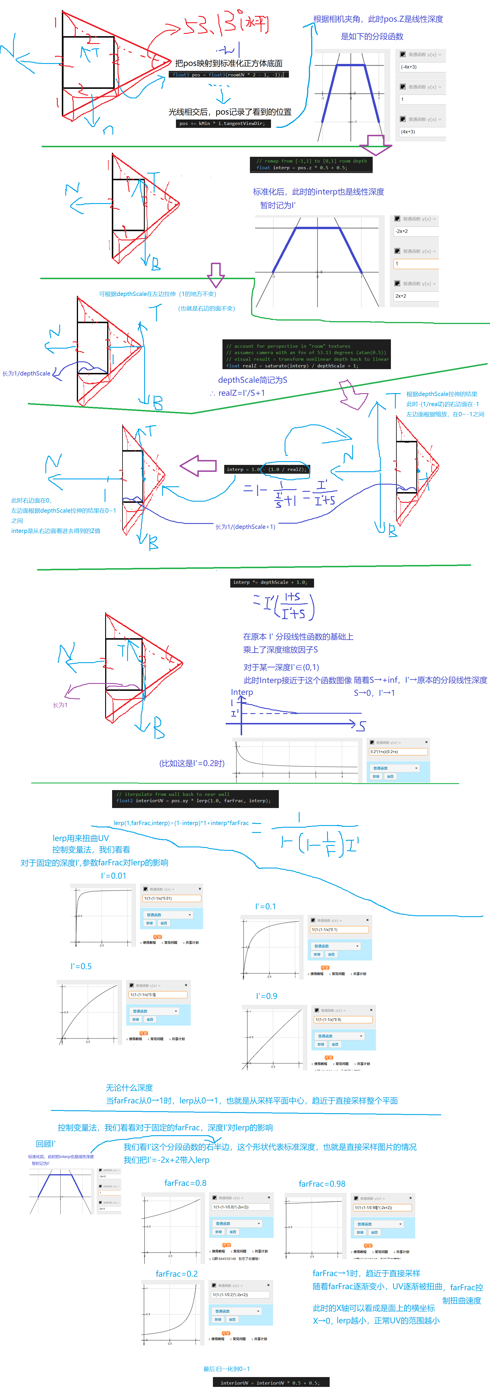
The results are shown in the figure
4.2.2 code
This part of the shader is as follows
// Upgrade NOTE: replaced 'mul(UNITY_MATRIX_MVP,*)' with 'UnityObjectToClipPos(*)'

Shader "MyShaders/InteriorMapping_2D"
{
	Properties
	{
		_RoomTex("Room Atlas RGB (A - back wall fraction)", 2D) = "white" {}
		_Rooms("Room Atlas Rows&Cols (XY)", Vector) = (1,1,0,0)
		_RoomDepth("Room Depth",range(0.001,0.999)) = 0.5
	}
		SubShader
		{
			Tags { "RenderType" = "Opaque" }
			LOD 100

			Pass
			{
				CGPROGRAM
				#pragma vertex vert
				#pragma fragment frag

				#include "UnityCG.cginc"

				struct appdata
				{
					float4 vertex : POSITION;
					float2 uv : TEXCOORD0;
					float3 normal : NORMAL;
					float4 tangent : TANGENT;
				};

				struct v2f
				{
					float4 pos : SV_POSITION;
					float2 uv : TEXCOORD0;
					float3 tangentViewDir : TEXCOORD1;
				};
				sampler2D _RoomTex;
				float4 _RoomTex_ST;
				float2 _Rooms;
				float _RoomDepth;
				v2f vert(appdata v)
				{
					v2f o;
					o.pos = UnityObjectToClipPos(v.vertex);
					o.uv = TRANSFORM_TEX(v.uv, _RoomTex);

					// get tangent space camera vector
					float4 objCam = mul(unity_WorldToObject, float4(_WorldSpaceCameraPos, 1.0));
					float3 viewDir = v.vertex.xyz - objCam.xyz;
					float tangentSign = v.tangent.w * unity_WorldTransformParams.w;
					float3 bitangent = cross(v.normal.xyz, v.tangent.xyz) * tangentSign;
					o.tangentViewDir = float3(
						dot(viewDir, v.tangent.xyz),
						dot(viewDir, bitangent),
						dot(viewDir, v.normal)
						);
					o.tangentViewDir *= _RoomTex_ST.xyx;
					return o;
				}

				// psuedo random
				float2 rand2(float co) {
					return frac(sin(co * float2(12.9898,78.233)) * 43758.5453);
				}

				fixed4 frag(v2f i) : SV_Target
				{
					// room uvs
					float2 roomUV = frac(i.uv);
					float2 roomIndexUV = floor(i.uv);

					// randomize the room
					float2 n = floor(rand2(roomIndexUV.x + roomIndexUV.y * (roomIndexUV.x + 1)) * _Rooms.xy);
					//float2 n = floor(_Rooms.xy);
					roomIndexUV += n;

					// get room depth from room atlas alpha
					// fixed farFrac = tex2D(_RoomTex, (roomIndexUV + 0.5) / _Rooms).a;

					// Specify depth manually
					fixed farFrac = _RoomDepth;

					//remap [0,1] to [+inf,0]
					//->if input _RoomDepth = 0    -> depthScale = 0      (inf depth room)
					//->if input _RoomDepth = 0.5  -> depthScale = 1
					//->if input _RoomDepth = 1    -> depthScale = +inf   (0 volume room)
					float depthScale = 1.0 / (1.0 - farFrac) - 1.0;

					// raytrace box from view dir
					// normalized box space's ray start pos is on trinagle surface, where z = -1
					float3 pos = float3(roomUV * 2 - 1, -1);
					// transform input ray dir from tangent space to normalized box space
					i.tangentViewDir.z *= -depthScale;


					float3 id = 1.0 / i.tangentViewDir;
					float3 k = abs(id) - pos * id;
					float kMin = min(min(k.x, k.y), k.z);
					pos += kMin * i.tangentViewDir;

					// remap from [-1,1] to [0,1] room depth
					float interp = pos.z * 0.5 + 0.5;

					// account for perspective in "room" textures
					// assumes camera with an fov of 53.13 degrees (atan(0.5))
					// visual result = transform nonlinear depth back to linear
					float realZ = saturate(interp) / depthScale + 1;
					interp = 1.0 - (1.0 / realZ);
					interp *= depthScale + 1.0;

					// iterpolate from wall back to near wall
					float2 interiorUV = pos.xy * lerp(1.0, farFrac, interp);

					interiorUV = interiorUV * 0.5 + 0.5;

					// sample room atlas texture
					fixed4 room = tex2D(_RoomTex, (roomIndexUV + interiorUV.xy) / _Rooms);
					return room;
				}
			ENDCG
		}
	}
	FallBack "Diffuse"
}
5 rich effect
As shown above, some results can be obtained by expanding the basic technology
In the following figure, 2d projection is used as the base, and alpha value is used to save the depth & manually specify the depth, randomly generate in the drawing set, and add window frame, Fresnel effect, window dirt, etc
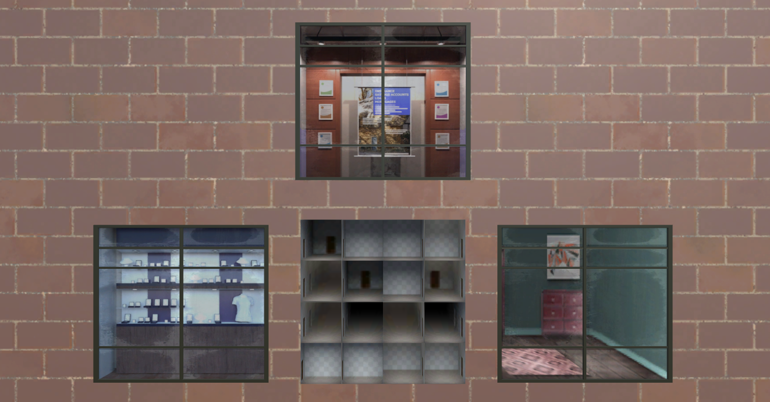
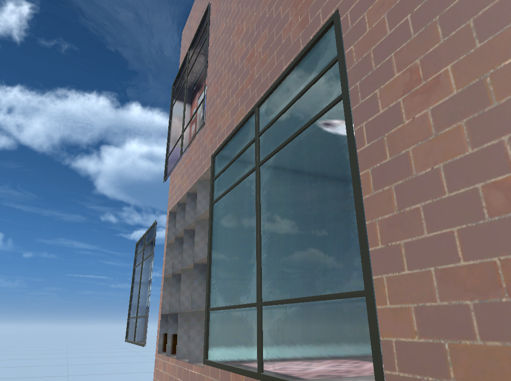
Other effects are also found, such as This article The SDF diagram of the window frame is used to simulate the lighting effect
In short, there is another interesting case (the middle part of the code idea of converting UV according to depth. I hope I can have the guidance of the great God. I don't understand Orz)