1. Introduction to design requirements and hardware environment
1.1 project background
Greening management system is widely used in real life and production. It is an integrated system integrating environmental perception, planning and decision-making, automatic management and so on. At present, the regional greening on both sides of urban roads are mainly flowers, grass, trees, shrubs, etc. among them, a variety of plants are highly sensitive to water. If the water supply is insufficient or excessive, it will cause wilting and even death. Moreover, manual management can not better understand the data of planting areas, resulting in a great waste of water resources. In response to the new progress in the construction of ecological civilization proposed in the national "14th five year plan", the allocation of energy resources is more reasonable, the utilization efficiency is greatly improved, and the ecological environment is continuously improved; Therefore, the development of advanced intelligent irrigation technology is very important for greening management.
The traditional manual greening management control mostly uses manual way to irrigate by observing the surface moisture, which not only causes the waste of water resources and human resources, but also the inaccurate irrigation. This paper uses Huawei cloud IOT Internet of things platform to design cloud greening management system. The equipment platform adopts bear development board - CPU is STM32L431 chip of Italy France semiconductor, which is a low-power chip launched by Italy France semiconductor; Cooperate with some external professional sensors to obtain the temperature and humidity data and illumination data in the air, and judge whether to carry out irrigation according to the air temperature and humidity data in the planting area. Therefore, the research on a greening management system with low price, wide application range and reliable performance is of great significance to improve the greening level and energy conservation and emission reduction.
1.2 realization of functions
In this project, STM32L431+ESP8266 WIFI of STMicroelectronics is used to cooperate with Huawei cloud Internet of things platform server to establish a micro greening management system, combined with the data collected by external sensors, and use these data to judge whether irrigation is carried out.
Considering the purpose of learning, the current project adopts ESP8266 wireless WIFI network card as networking equipment. ESP8266 is cheap, supports serial port programming, and has a standard set of AT data. There are many data. It is very suitable for learning. Through the programming experiment of ESP8266, you can understand the knowledge points related to TCP and MQTT network programming.
The current project is mainly divided into six functional modules: basic system module, temperature acquisition module, humidity acquisition module, light acquisition module, wireless sensor network module and OLED display module. (1) Basic system module: receive and forward various data to control whether the sweeping operation is carried out. The watering operation adopts on-board motor simulation (2) temperature acquisition module: collect the temperature data in the monitoring area and transmit it to the microcontroller (3) humidity acquisition module: collect the humidity data in the monitoring area, Transmission to the microcontroller (4) lighting acquisition module: collect the lighting data of the monitoring area and transmit it to the microcontroller (5) wireless sensor network module: upload the data to the cloud platform, distribute the data interactively, etc. (6) LCD display module: display the monitored data in real time
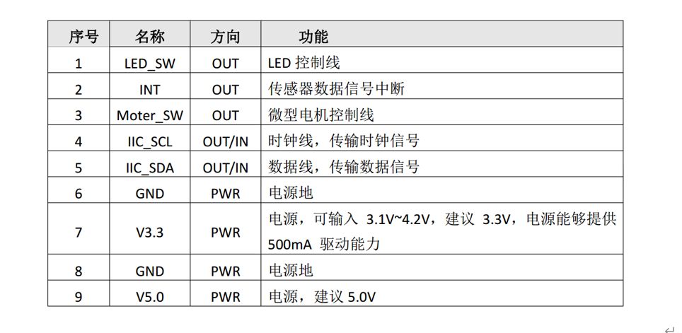
The expansion board of little bear development board is equipped with photosensitive sensor, temperature and humidity sensor and DC motor module, which can easily realize these functional requirements.
The source code of this project does not use the official case project. The official project is very large. In order to be compatible with various equipment platforms, there are many codes, which are not suitable for beginners to understand the code. The engineering codes in this paper are all written for this project, there is no redundant code, and are written in register style. The code is concise, which is very suitable for beginners to learn MQTT protocol, Learn the communication protocols of various sensors and so on; The MQTT protocol for connecting Huawei cloud is also written in accordance with the official Chinese Manual of MQTT. It does not rely on any external SDK or ESP8266 devices. As long as the devices that can be connected to the network can be connected to Huawei cloud IOT, it is very suitable for transplantation to other MCU platforms; Whether using 51 or STM32F1 series, you can directly refer to code transplantation.
 https://download.csdn.net/download/xiaolong1126626497/67931599
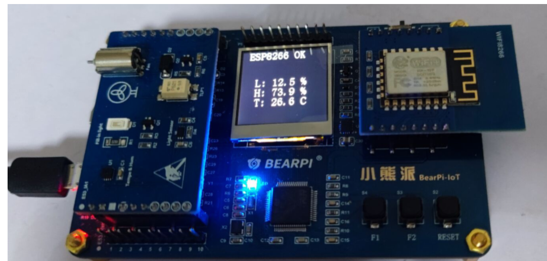
1.3 physical drawing of equipment
Relevant physical drawings of equipment of Xiaoxiong development board are as follows:


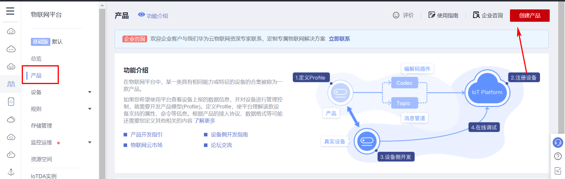
2. Create IOT server-side products
2.1 creating products
Directly open the Internet of things product page: Device access_ IoTDA_IoT_ IOT platform - Hua Weiyun

Open the product page and select create product in the upper right corner.
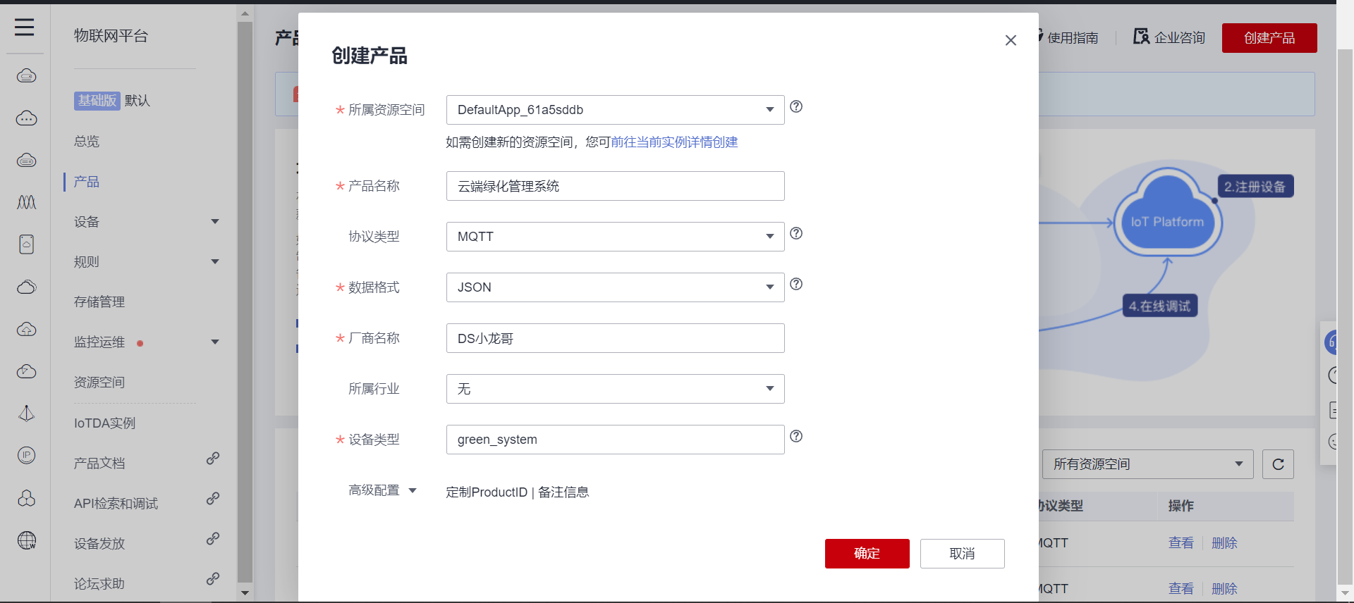
Fill in the information according to your own situation.
After successful creation, open the product details page, pull to the bottom, and click create custom model file.
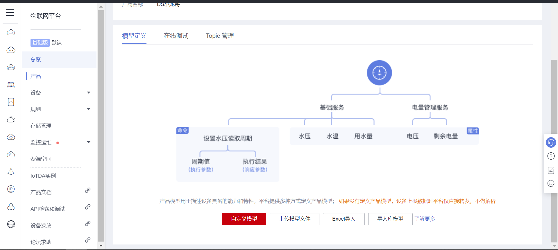
The purpose of creating model files here is to enable the MQTT client to upload sensor data correctly. Each sensor sets a property that represents the data value type of the sensor.
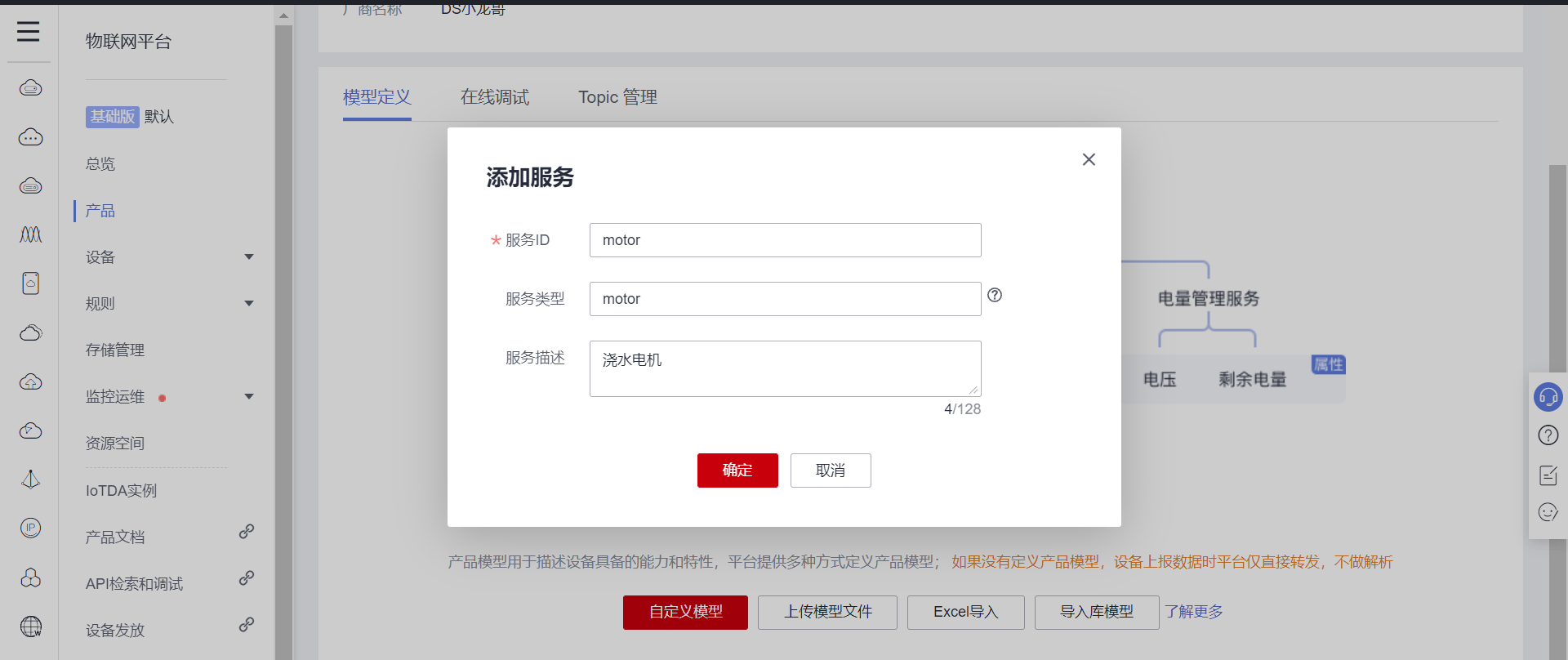
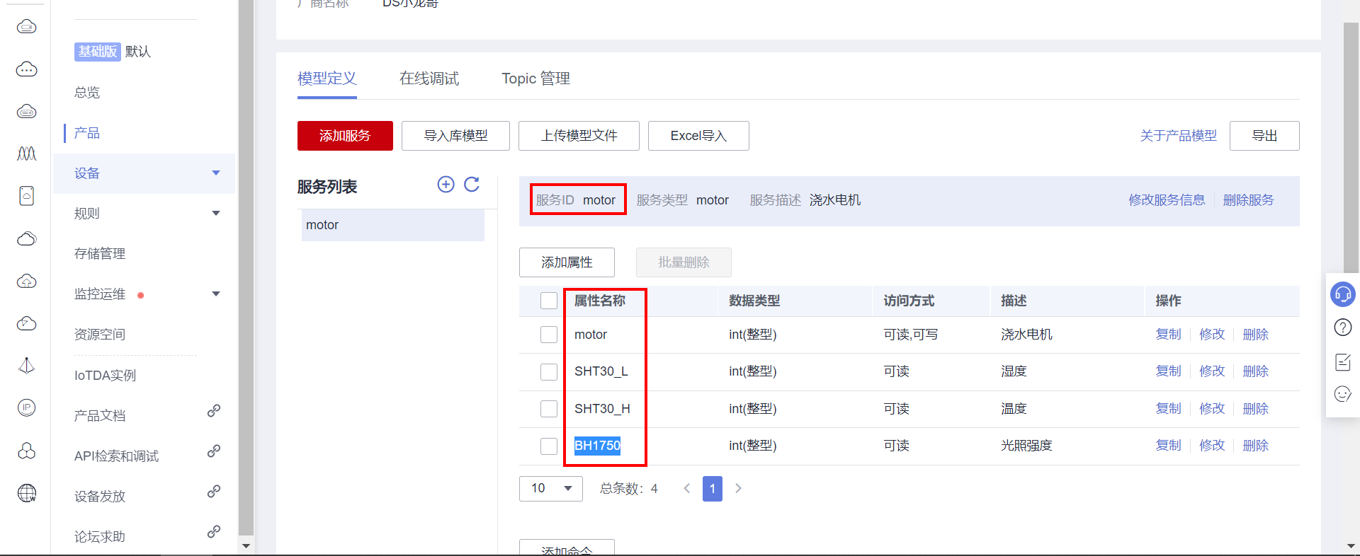
For example, first add a motor, which is a watering motor, which can report the switch status, and the cloud can also send commands to control the motor, so you need to add attributes and commands.
Add attribute:

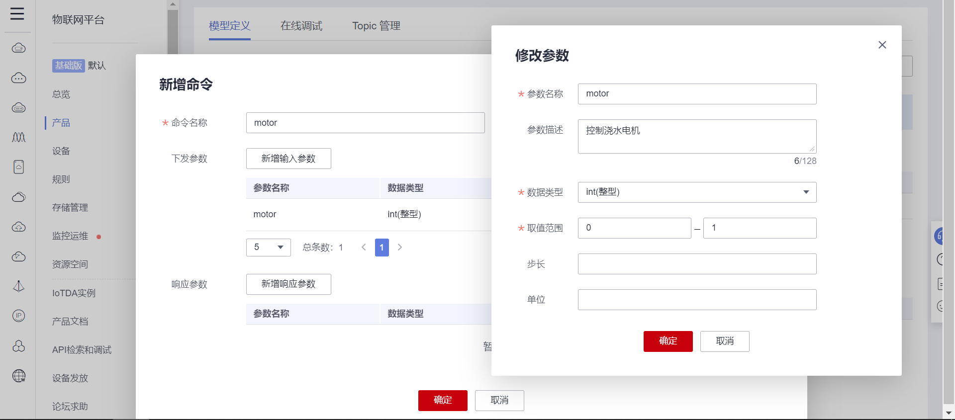
Add command: because the motor needs cloud remote control.
Next, create the attributes of temperature, humidity and illumination sensors. These sensors only upload data to the cloud and do not need to issue instructions for control, so just create the attributes.
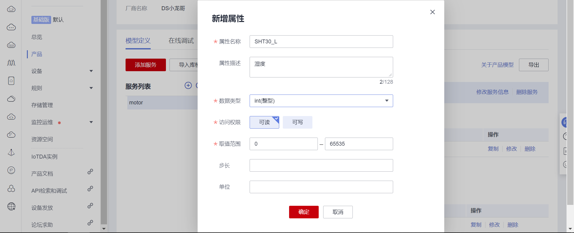

After the effect is created, there are 4 attributes: motor, temperature, humidity and light intensity:
2.2 creating equipment
Select the device page to register the device.
After creation, keep the device key and other information. These parameters are required to generate the MQTT account key when logging in to the server.
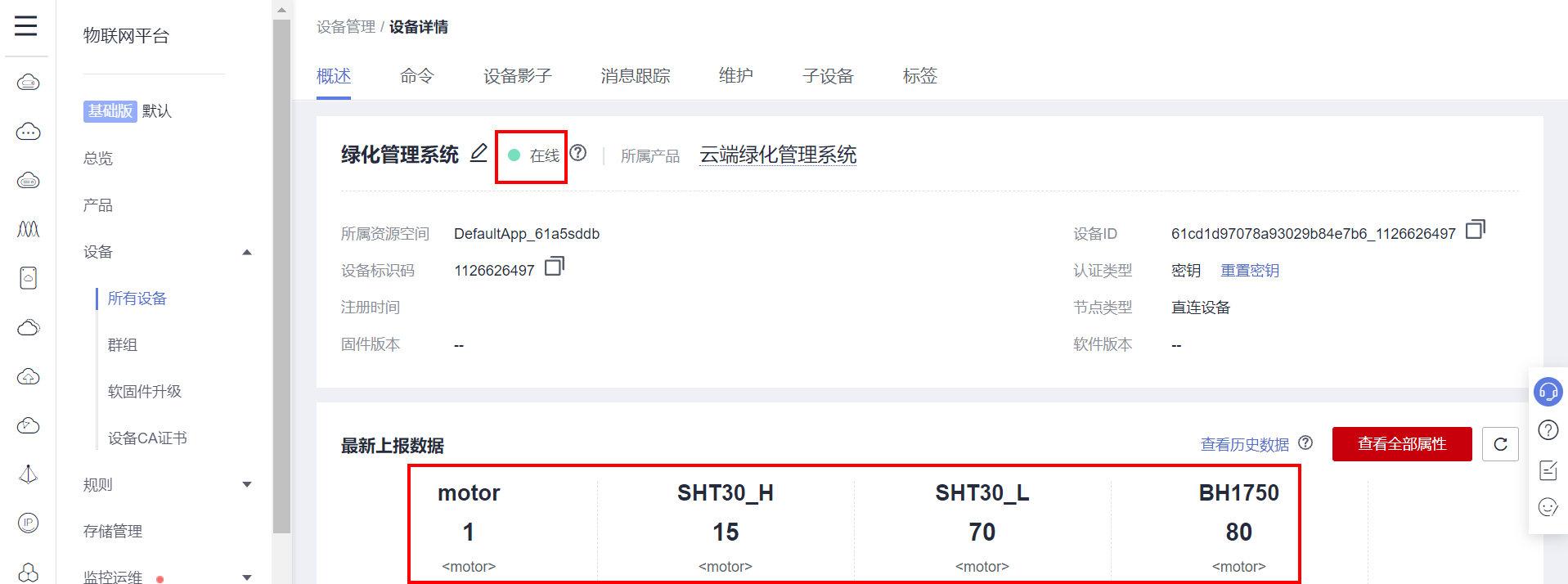
The currently created device information is as follows:
{
    "device_id": "61cd1d97078a93029b84e7b6_1126626497",
    "secret": "1126626497"
}
2.3 generate MQTT login account information
Online gadgets provided by official wechat: Huaweicloud IoTDA Mqtt ClientId Generator
Fill in the data according to the prompt and generate it, which is very convenient.
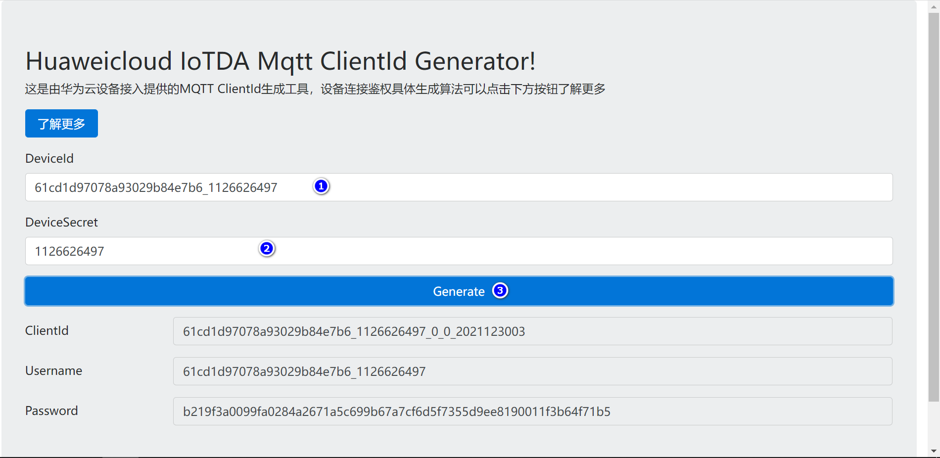
The currently generated information is as follows:
ClientId 61cd1d97078a93029b84e7b6_1126626497_0_0_2021123003
Username 61cd1d97078a93029b84e7b6_1126626497
Password b219f3a0099fa0284a2671a5c699b67a7cf6d5f7355d9ee8190011f3b64f71b5
3. Use MQTT client simulation test
In order to verify whether the server configuration is OK, first use MQTT client software for connection test.
3.1 address and port of Huawei cloud IOT server
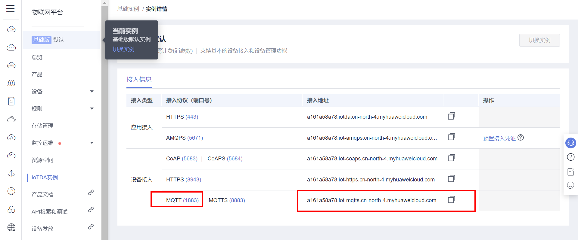
Port: 1883
 Domain name: a161a58a78 iot-mqtts. cn-north-4. myhuaweicloud. com
 IP address: 121.36.42.100
3.2 subscription topics
On the product page, you can see the topic management page, which topics the current device can subscribe to.
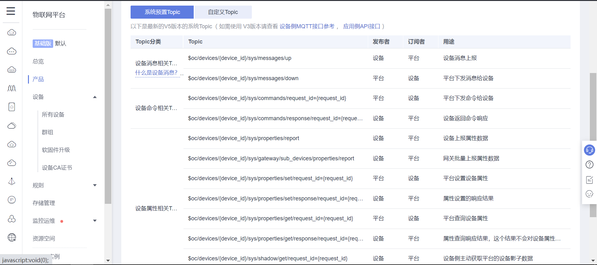
Data distributed by general subscription:
Format: $oc/devices/{device_id}/sys/messages/down
 //Subscription subject: the platform sends messages to devices
$oc/devices/61cd1d97078a93029b84e7b6_1126626497/sys/messages/down
3.3 reporting subject data
Introduction to official documents: Use mqtt FX commissioning_ Device access IoTDA_ Development Guide_ Equipment side development_ Access using MQTT Demo_ Hua Weiyun
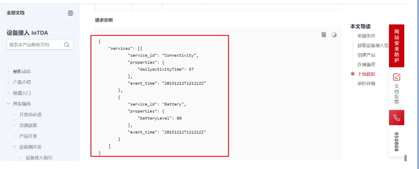
Service ID and attribute ID are viewed on the product page. The function of this attribute is described in creating a product in Section 2.1.
A single attribute can be submitted each time, or they can be submitted together.
Format: $oc/devices/{device_id}/sys/properties/report
//Device submission subject request
$oc/devices/61cd1d97078a93029b84e7b6_1126626497/sys/properties/report
//The format of reported data is as follows:
//Motor on state feedback
{"services": [{"service_id": "motor","properties":{"motor":1}}]}
//Motor off state feedback
{"services": [{"service_id": "motor","properties":{"motor":0}}]}
//Temperature reporting
{"services": [{"service_id": "motor","properties":{"SHT30_H":14}}]}
//Humidity reporting
{"services": [{"service_id": "motor","properties":{"SHT30_L":70}}]}
//Light intensity Report
{"services": [{"service_id": "motor","properties":{"BH1750":80}}]}
//They can also be reported together
{"services": [{"service_id": "motor","properties":{"motor":1}},{"service_id": "motor","properties":{"SHT30_H":15}},{"service_id": "motor","properties":{"SHT30_L":70}},{"service_id": "motor","properties":{"BH1750":80}}]}
3.4 login server
Fill in relevant data according to the software prompt.
If necessary, you also need to use the same software as me to open Baidu search MQTT client_ v2. 4 (agreement 3.1.1) Exe to find the download address.
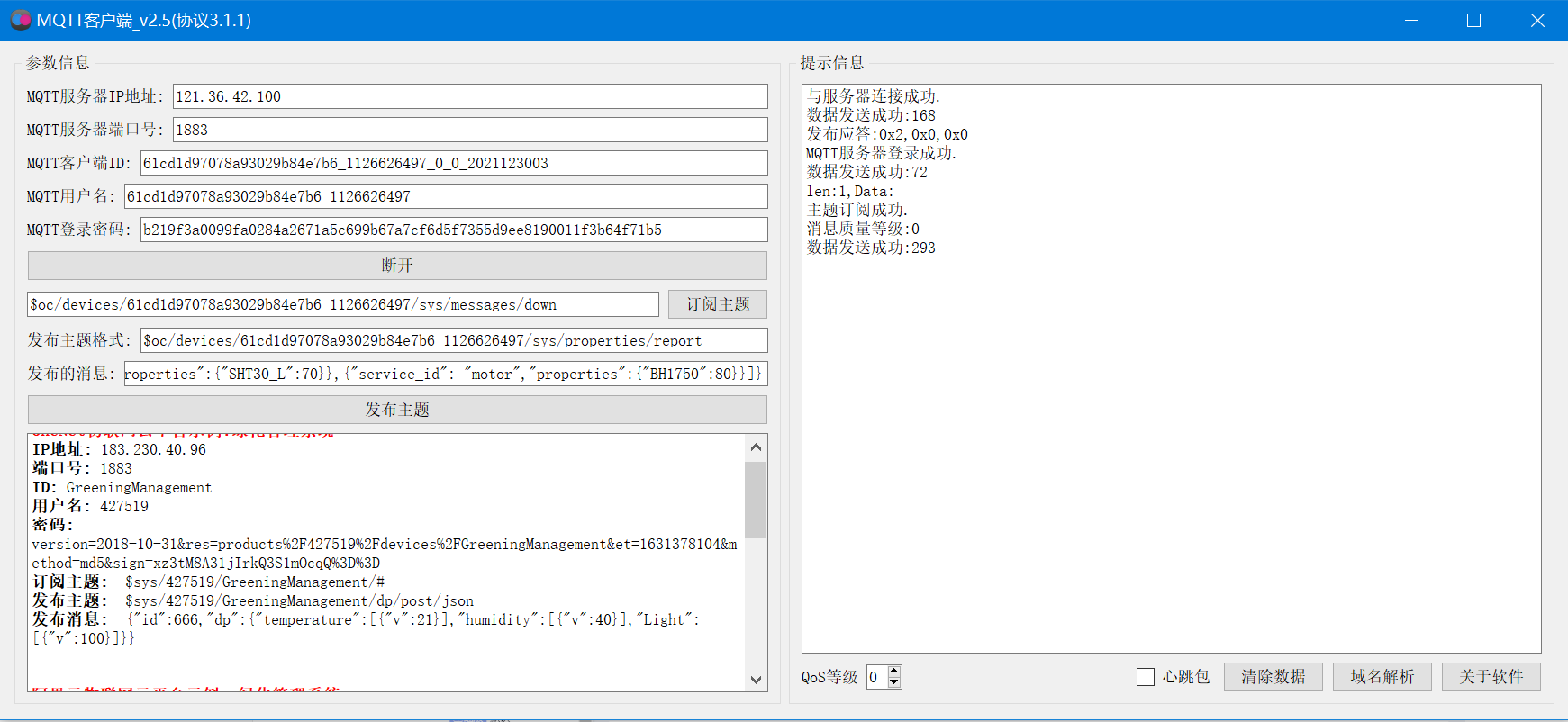
After sending the data, check the cloud. The login has been successful and the data has been uploaded successfully.
3.5 issuing orders
The motor equipment supports reading and writing, issuing commands and testing on the equipment page.
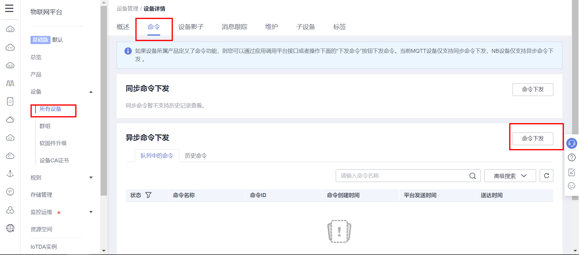

After clicking OK, refer to MQTT client software, and the distributed data has been received.
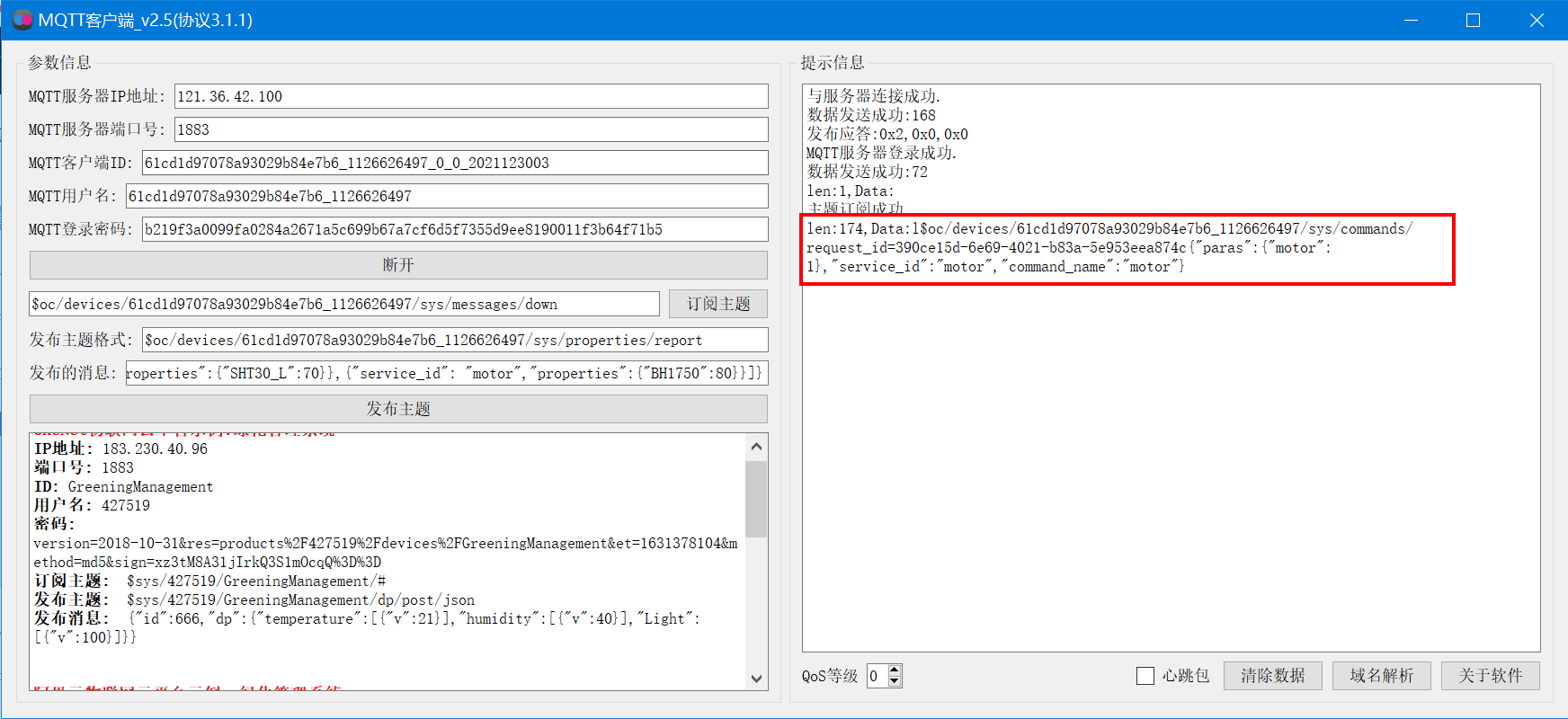
len:174,Data:l$oc/devices/61cd1d97078a93029b84e7b6_1126626497/sys/commands/request_id=390ce15d-6e69-4021-b83a-5e953eea874c{"paras":{"motor":1},"service_id":"motor","command_name":"motor"}
4. Huawei cloud IOT on the device end
Project code:

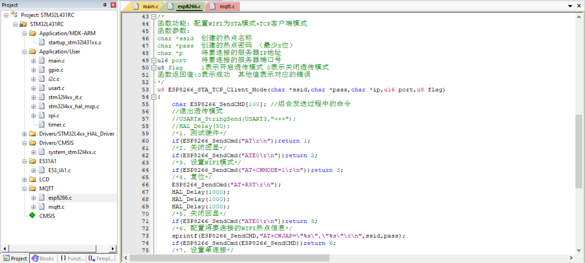
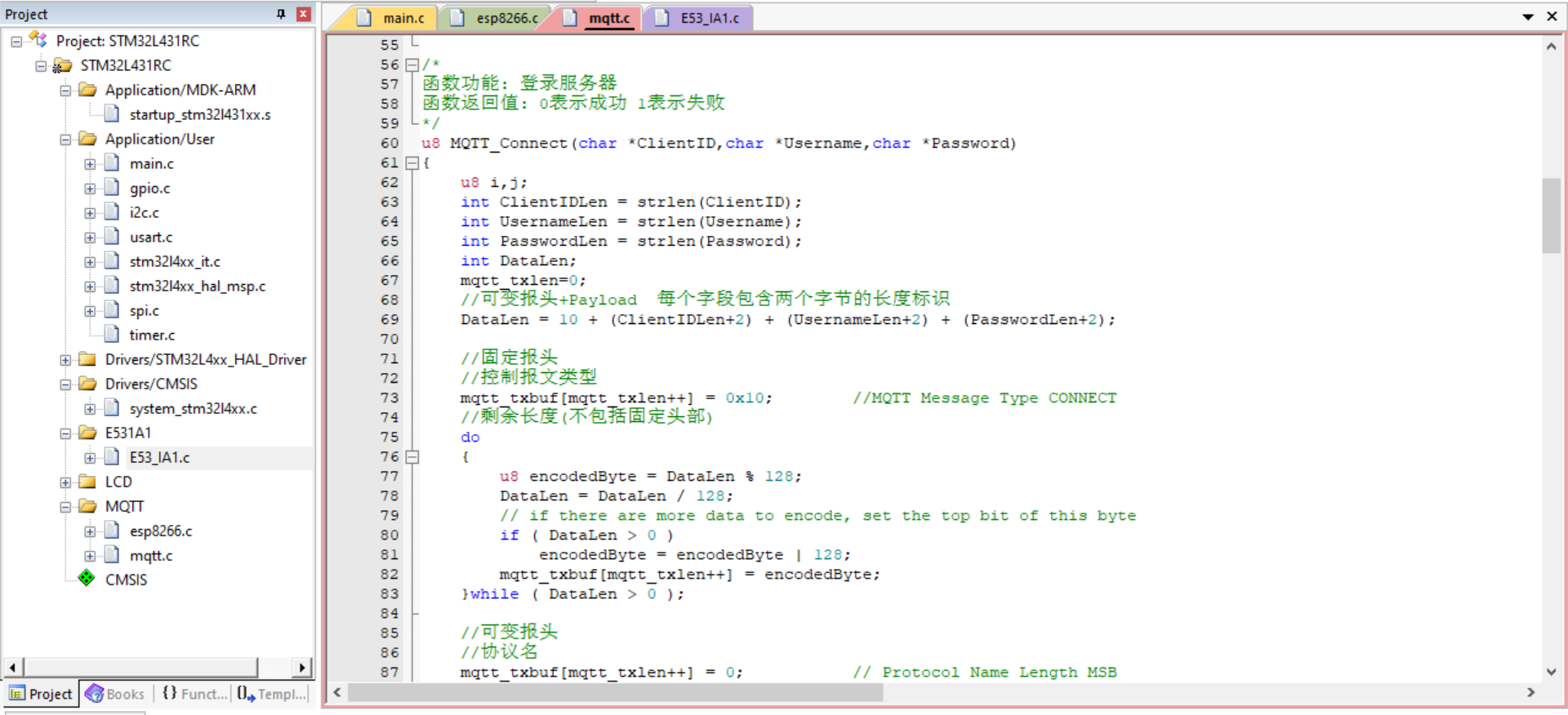
There are many engineering codes, so post main here C all codes:
#include "main.h"
#include "stm32l4xx_hal.h"
#include "i2c.h"
#include "usart.h"
#include "gpio.h"
#include "E53_IA1.h"
#include "lcd.h"
#include "spi.h"
#include "mqtt.h"
#include "esp8266.h"
/* USER CODE BEGIN Includes */
#include "stdio.h"
/* USER CODE END Includes */
void SystemClock_Config(void);
#define ESP8266_ WIFI_ AP_ SSID "CMCC cqvn" / / the name of the router to be connected -- do not appear Chinese, spaces and other special characters
#define ESP8266_AP_PASSWORD "99pu58cb" / / password of the router to be connected
//Device information of Huawei cloud IOT server
#define MQTT_ClientID "61cd1d97078a93029b84e7b6_1126626497_0_0_2021123003"
#define MQTT_UserName "61cd1d97078a93029b84e7b6_1126626497"
#define MQTT_PassWord "b219f3a0099fa0284a2671a5c699b67a7cf6d5f7355d9ee8190011f3b64f71b5"
//Topics for subscriptions and publications
#define SET_ Topic "$OC / devices / 61cd1d97078a93029b84e7b6_1126626497 / sys / messages / down" / / subscription
#define POST_TOPIC "$oc/devices/61cd1d97078a93029b84e7b6_1126626497/sys/properties/report" / / publish
//Storage temperature, humidity and light intensity
E53_IA1_Data_TypeDef E53_IA1_Data;
//Display text
char lcd_text_str[50];
UART_HandleTypeDef at_usart;
//Low power serial port initialization
int32_t at_usart_init(void)
{
at_usart.Instance = LPUART1;
at_usart.Init.BaudRate = 115200;
at_usart.Init.WordLength = UART_WORDLENGTH_8B;
at_usart.Init.StopBits = UART_STOPBITS_1;
at_usart.Init.Parity = UART_PARITY_NONE;
at_usart.Init.HwFlowCtl = UART_HWCONTROL_NONE;
at_usart.Init.Mode = UART_MODE_RX | UART_MODE_TX;
if(HAL_UART_Init(&at_usart) != HAL_OK)
{
_Error_Handler(__FILE__, __LINE__);
}
// __HAL_UART_CLEAR_FLAG(usart, UART_FLAG_TC);
__HAL_UART_ENABLE_IT(&at_usart, UART_IT_IDLE);
__HAL_UART_ENABLE_IT(&at_usart, UART_IT_RXNE);
HAL_NVIC_EnableIRQ(LPUART1_IRQn); //Enable USART1 interrupt channel
HAL_NVIC_SetPriority(LPUART1_IRQn, 3, 3); //Preemption priority 3, sub priority 3
return 0;
}
unsigned char ESP8266_RecvBuf[MAX_RECV_CNT];
unsigned int ESP8266_Recv_cnt=0;
unsigned int ESP8266_Recv_flag=0;
void LPUART1_IRQHandler()
{
//Data received
if(__HAL_UART_GET_FLAG(&at_usart, UART_FLAG_RXNE) != RESET)
{
if(ESP8266_Recv_cnt<MAX_RECV_CNT-1)
{
ESP8266_RecvBuf[ESP8266_Recv_cnt++] = (uint8_t)(at_usart.Instance->RDR & 0x00FF);
}
else
{
ESP8266_Recv_flag=1;
}
}
else if (__HAL_UART_GET_FLAG(&at_usart, UART_FLAG_IDLE) != RESET)
{
__HAL_UART_CLEAR_IDLEFLAG(&at_usart);
ESP8266_Recv_flag=1;
}
}
void AT_SendData(unsigned char *p,unsigned int len)
{
int i=0;
for(i=0;i<len;i++)
{
while((LPUART1->ISR & 0X40) == 0); //Cycle sending until sending is completed
LPUART1->TDR = p[i];
}
}
char mqtt_message[200];
int main(void)
{
int i=0;
int cnt=0;
int motor_state=0;
HAL_Init();
SystemClock_Config();
MX_GPIO_Init();
MX_I2C1_Init();
MX_SPI2_Init();
MX_USART1_UART_Init();
at_usart_init();
//Initialize hardware
Init_E53_IA1();
LCD_Init();
LCD_Clear(BLACK);//The clear screen is black
LCD_ShowString(0, 00, 240, 32, 32, "Init ESP8266");//Display string, font size 32 * 32
if(ESP8266_Init())
{
printf("ESP8266 Hardware detection error.\n");
LCD_Clear(BLACK);//The clear screen is black
LCD_ShowString(0, 00, 240, 32, 32, "ESP8266 ERROR");//Display string, font size 32 * 32
}
else
{
LCD_Clear(BLACK);//The clear screen is black
LCD_ShowString(0, 00, 240, 32, 32, "ESP8266 OK");//Display string, font size 32 * 32
printf("Preparing to connect to the specified server.\n");
//Unencrypted port
printf("WIFI:%d\r\n",ESP8266_STA_TCP_Client_Mode(ESP8266_WIFI_AP_SSID,ESP8266_AP_PASSWORD,"106.55.124.154",1883,1));
}
//2. MQTT protocol initialization
MQTT_Init();
//3. Connect Huawei cloud IOT server
while(MQTT_Connect(MQTT_ClientID,MQTT_UserName,MQTT_PassWord))
{
printf("Server connection failed,Retrying...\n");
HAL_Delay(500);
}
printf("Server connection succeeded.\n");
//3. Subscribe to topics
if(MQTT_SubscribeTopic(SET_TOPIC,0,1))
{
printf("Topic subscription failed.\n");
}
else
{
printf("Topic subscription succeeded.\n");
}
while (1)
{
if(HAL_GPIO_ReadPin(KEY1_GPIO_Port,KEY1_Pin)==GPIO_PIN_RESET)//Query key KEY1 low level
{
HAL_Delay(10);//Debounce
if(HAL_GPIO_ReadPin(KEY1_GPIO_Port,KEY1_Pin)==GPIO_PIN_RESET)//Query key KEY1 low level
{
HAL_GPIO_WritePin(LED_GPIO_Port,LED_Pin,GPIO_PIN_SET);//bright
//Fill light on
HAL_GPIO_WritePin(IA1_Light_GPIO_Port, IA1_Light_Pin, GPIO_PIN_SET);
//Motor rotation
HAL_GPIO_WritePin(IA1_Motor_GPIO_Port, IA1_Motor_Pin, GPIO_PIN_SET);
motor_state=1;
}
}
if(HAL_GPIO_ReadPin(KEY2_GPIO_Port,KEY2_Pin)==GPIO_PIN_RESET)//Query key KEY2 low level
{
HAL_Delay(10);//Debounce
if(HAL_GPIO_ReadPin(KEY2_GPIO_Port,KEY2_Pin)==GPIO_PIN_RESET)//Query key KEY2 low level
{
HAL_GPIO_WritePin(LED_GPIO_Port,LED_Pin,GPIO_PIN_RESET);//Extinguish
//Fill light off
HAL_GPIO_WritePin(IA1_Light_GPIO_Port, IA1_Light_Pin, GPIO_PIN_RESET);
//Motor stop
HAL_GPIO_WritePin(IA1_Motor_GPIO_Port, IA1_Motor_Pin, GPIO_PIN_RESET);
motor_state=0;
}
}
cnt++;
HAL_Delay(10);
if(cnt>=100)
{
cnt=0;
E53_IA1_Read_Data();
printf("Light intensity:%d %%\r\n", (int)E53_IA1_Data.Lux);
printf("humidity:%d %%\r\n",(int)E53_IA1_Data.Humidity);
printf("temperature:%d ℃\r\n", (int)E53_IA1_Data.Temperature);
sprintf(lcd_text_str,"L: %d %%",(int)E53_IA1_Data.Lux);
LCD_ShowString(40, 50+10+32*1, 240, 32, 32,lcd_text_str);
sprintf(lcd_text_str,"H: %d %%",(int)E53_IA1_Data.Humidity);
LCD_ShowString(40, 50+10+32*2, 240, 32, 32,lcd_text_str);
sprintf(lcd_text_str,"T: %d C",(int)E53_IA1_Data.Temperature);
LCD_ShowString(40, 50+10+32*3, 240, 32, 32,lcd_text_str);
//State of switching pin
HAL_GPIO_TogglePin(LED_GPIO_Port,LED_Pin);
//Upload data
sprintf(mqtt_message,"{\"services\": [{\"service_id\": \"motor\",\"properties\":{\"motor\":%d}},"
"{\"service_id\": \"motor\",\"properties\":{\"SHT30_H\":%d}},{\"service_id\": \"motor\",\"properties\":"
"{\"SHT30_L\":%d}},{\"service_id\": \"motor\",\"properties\":{\"BH1750\":%d}}]}",
motor_state,(int)E53_IA1_Data.Humidity,(int)E53_IA1_Data.Temperature,(int)E53_IA1_Data.Lux);
MQTT_PublishData(POST_TOPIC,mqtt_message,0);
//Automatic irrigation according to humidity
if((int)E53_IA1_Data.Humidity<50) //Less than 50 automatic irrigation
{
printf("Automatic irrigation....\n");
motor_state=1; //Motor status update
//Motor rotation
HAL_GPIO_WritePin(IA1_Motor_GPIO_Port, IA1_Motor_Pin, GPIO_PIN_SET);
}
}
//Data received
if(ESP8266_Recv_flag)
{
//If the attribute is issued, judge whether to unlock or close the lock
if(ESP8266_Recv_cnt>5)
{
ESP8266_RecvBuf[ESP8266_Recv_cnt]='\0';
//Use string lookup function
if(strstr((char*)&ESP8266_RecvBuf[5],"\"machine\":1"))
{
motor_state=1; //Motor status update
//Motor rotation
HAL_GPIO_WritePin(IA1_Motor_GPIO_Port, IA1_Motor_Pin, GPIO_PIN_SET);
printf("Turn on the motor...\n");
}
else if(strstr((char*)&ESP8266_RecvBuf[5],"\"machine\":0"))
{
//Motor stop
HAL_GPIO_WritePin(IA1_Motor_GPIO_Port, IA1_Motor_Pin, GPIO_PIN_RESET);
motor_state=0;
printf("Turn off the motor...\n");
}
for(i=0;i<ESP8266_Recv_cnt;i++)printf("%c",ESP8266_RecvBuf[i]);
ESP8266_Recv_cnt=0;
}
ESP8266_Recv_flag=0;
}
}
}
void SystemClock_Config(void)
{
RCC_OscInitTypeDef RCC_OscInitStruct;
RCC_ClkInitTypeDef RCC_ClkInitStruct;
RCC_PeriphCLKInitTypeDef PeriphClkInit;
/**Initializes the CPU, AHB and APB busses clocks
*/
RCC_OscInitStruct.OscillatorType = RCC_OSCILLATORTYPE_HSI|RCC_OSCILLATORTYPE_MSI;
RCC_OscInitStruct.HSIState = RCC_HSI_ON;
RCC_OscInitStruct.HSICalibrationValue = 16;
RCC_OscInitStruct.MSIState = RCC_MSI_ON;
RCC_OscInitStruct.MSICalibrationValue = 0;
RCC_OscInitStruct.MSIClockRange = RCC_MSIRANGE_6;
RCC_OscInitStruct.PLL.PLLState = RCC_PLL_ON;
RCC_OscInitStruct.PLL.PLLSource = RCC_PLLSOURCE_MSI;
RCC_OscInitStruct.PLL.PLLM = 1;
RCC_OscInitStruct.PLL.PLLN = 40;
RCC_OscInitStruct.PLL.PLLP = RCC_PLLP_DIV7;
RCC_OscInitStruct.PLL.PLLQ = RCC_PLLQ_DIV2;
RCC_OscInitStruct.PLL.PLLR = RCC_PLLR_DIV2;
if (HAL_RCC_OscConfig(&RCC_OscInitStruct) != HAL_OK)
{
_Error_Handler(__FILE__, __LINE__);
}
/**Initializes the CPU, AHB and APB busses clocks
*/
RCC_ClkInitStruct.ClockType = RCC_CLOCKTYPE_HCLK|RCC_CLOCKTYPE_SYSCLK
|RCC_CLOCKTYPE_PCLK1|RCC_CLOCKTYPE_PCLK2;
RCC_ClkInitStruct.SYSCLKSource = RCC_SYSCLKSOURCE_PLLCLK;
RCC_ClkInitStruct.AHBCLKDivider = RCC_SYSCLK_DIV1;
RCC_ClkInitStruct.APB1CLKDivider = RCC_HCLK_DIV1;
RCC_ClkInitStruct.APB2CLKDivider = RCC_HCLK_DIV1;
if (HAL_RCC_ClockConfig(&RCC_ClkInitStruct, FLASH_LATENCY_4) != HAL_OK)
{
_Error_Handler(__FILE__, __LINE__);
}
PeriphClkInit.PeriphClockSelection = RCC_PERIPHCLK_USART1|RCC_PERIPHCLK_I2C1;
PeriphClkInit.Usart1ClockSelection = RCC_USART1CLKSOURCE_PCLK2;
PeriphClkInit.I2c1ClockSelection = RCC_I2C1CLKSOURCE_HSI;
if (HAL_RCCEx_PeriphCLKConfig(&PeriphClkInit) != HAL_OK)
{
_Error_Handler(__FILE__, __LINE__);
}
/**Configure the main internal regulator output voltage
*/
if (HAL_PWREx_ControlVoltageScaling(PWR_REGULATOR_VOLTAGE_SCALE1) != HAL_OK)
{
_Error_Handler(__FILE__, __LINE__);
}
/**Configure the Systick interrupt time
*/
HAL_SYSTICK_Config(HAL_RCC_GetHCLKFreq()/1000);
/**Configure the Systick
*/
HAL_SYSTICK_CLKSourceConfig(SYSTICK_CLKSOURCE_HCLK);
/* SysTick_IRQn interrupt configuration */
HAL_NVIC_SetPriority(SysTick_IRQn, 0, 0);
}
/* USER CODE BEGIN 4 */
/* USER CODE END 4 */
/**
* @brief This function is executed in case of error occurrence.
* @param file: The file name as string.
* @param line: The line in file as a number.
* @retval None
*/
void _Error_Handler(char *file, int line)
{
/* USER CODE BEGIN Error_Handler_Debug */
/* User can add his own implementation to report the HAL error return state */
while(1)
{
}
/* USER CODE END Error_Handler_Debug */
}
#ifdef USE_FULL_ASSERT
/**
* @brief Reports the name of the source file and the source line number
* where the assert_param error has occurred.
* @param file: pointer to the source file name
* @param line: assert_param error line source number
* @retval None
*/
void assert_failed(uint8_t* file, uint32_t line)
{
/* USER CODE BEGIN 6 */
/* User can add his own implementation to report the file name and line number,
tex: printf("Wrong parameters value: file %s on line %d\r\n", file, line) */
/* USER CODE END 6 */
}
#endif /* USE_FULL_ASSERT */