brief introduction
The main purpose of this paper is to establish the communication connection between STM32 and Dynamixel steering gear, develop the control framework of upper computer lower computer steering gear, issue instructions in the upper computer, the lower computer executes the outer loop of steering gear force control, and the steering gear realizes the inner loop of position control. Among them, serial communication is adopted between the upper computer and the lower computer, and between the lower computer and the steering gear (the upper computer and the lower computer communicate through USART1, and the lower computer and the steering gear communicate through RS485(USART2)).
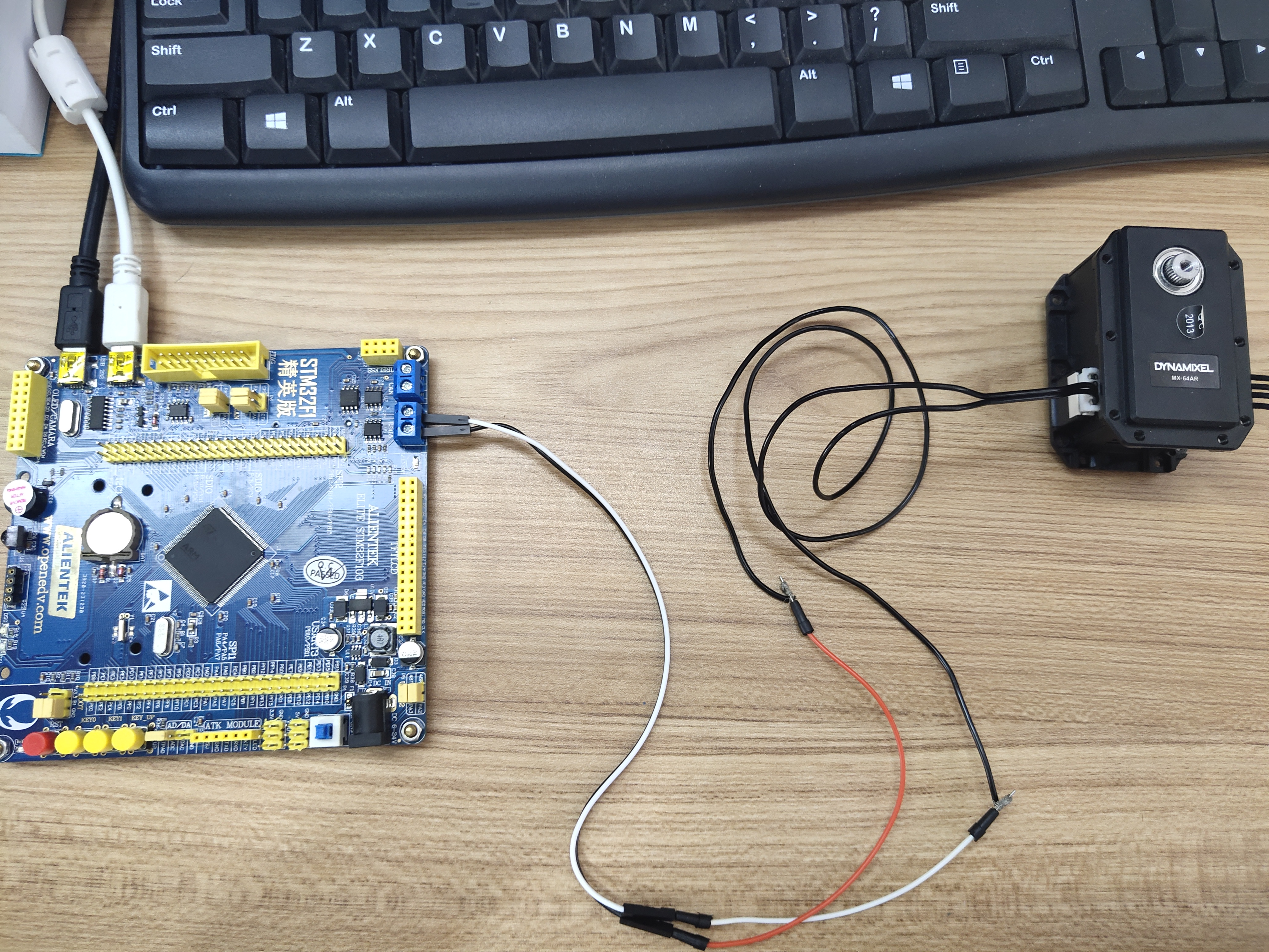
hardware platform
The hardware involved in this paper is:
- STM32F1 Elite Edition
- Dynamixel MX64 AR (protocol 1.0)
- Feite bus steering gear USB to RS485/TTL adapter board (instead of U2D2)
Hardware connection
be careful
- RS485 connection cannot be reversed, that is: a < – > A, B < – > b, a port of MX 64AR is Data +, and B port is Data-
- RS485 only defines the physical interface and electrical characteristics, and does not specify the specific protocol
MX64 protocol
The implementation of steering gear control protocol mainly refers to the official manual. For details, see:
Link 1 It mainly focuses on the Control table, which defines the location (EEPROM, RAM), register address and length of each register of the steering gear. The typical attributes are as follows:
[control table]
# addr | item name                | length | access | memory |   min value   |  max value  | signed
   0   | model_number             | 2      | R      | EEPROM | 0             | 65535       | N
   2   | version_of_firmware      | 1      | R      | EEPROM | 0             | 254         | N
   3   | ID                       | 1      | RW     | EEPROM | 0             | 252         | N
   4   | baudrate                 | 1      | RW     | EEPROM | 0             | 252         | N
   5   | return_delay_time        | 1      | RW     | EEPROM | 0             | 254         | N
   6   | CW_angle_limit           | 2      | RW     | EEPROM | 0             | 4095        | N
   8   | CCW_angle_limit          | 2      | RW     | EEPROM | 0             | 4095        | N
   10  | drive_mode               | 1      | RW     | EEPROM | 0             | 3           | N
   11  | max_temperature_limit    | 1      | RW     | EEPROM | 0             | 99          | N
   12  | min_voltage_limit        | 1      | RW     | EEPROM | 0             | 250         | N
   13  | max_voltage_limit        | 1      | RW     | EEPROM | 0             | 250         | N
   14  | max_torque               | 2      | RW     | EEPROM | 0             | 1023        | N
   16  | status_return_level      | 1      | RW     | EEPROM | 0             | 2           | N
   17  | alarm_LED                | 1      | RW     | EEPROM | 0             | 127         | N
   18  | alarm_shutdown           | 1      | RW     | EEPROM | 0             | 127         | N
   20  | multi_turn_offset        | 2      | RW     | EEPROM | -26624        | 26624       | Y
   22  | resolution_dividor       | 1      | RW     | EEPROM | 1             | 255         | N
   24  | torque_enable            | 1      | RW     | RAM    | 0             | 1           | N
   25  | LED                      | 1      | RW     | RAM    | 0             | 1           | N
   26  | position_d_gain          | 1      | RW     | RAM    | 0             | 254         | N
   27  | position_i_gain          | 1      | RW     | RAM    | 0             | 254         | N
   28  | position_p_gain          | 1      | RW     | RAM    | 0             | 254         | N
   30  | goal_position            | 2      | RW     | RAM    | -28672        | 28672       | Y
   32  | goal_velocity            | 2      | RW     | RAM    | 0             | 1023        | N
   34  | goal_torque              | 2      | RW     | RAM    | 0             | 1023        | N
   36  | present_position         | 2      | R      | RAM    | -32768        | 32767       | Y
   38  | present_velocity         | 2      | R      | RAM    | 0             | 2048        | N
   40  | present_load             | 2      | R      | RAM    | 0             | 2048        | N
   42  | present_voltage          | 1      | R      | RAM    | 50            | 250         | N
   43  | present_temperature      | 1      | R      | RAM    | 0             | 99          | N
   44  | registered_instruction   | 1      | R      | RAM    | 0             | 1           | N
   46  | is_moving                | 1      | R      | RAM    | 0             | 1           | N
   47  | EEPROM_lock              | 1      | RW     | RAM    | 0             | 1           | N
   48  | punch                    | 2      | RW     | RAM    | 0             | 1023        | N
   68  | current_consumption      | 2      | RW     | RAM    | 0             | 4095        | N
   70  | torque_control_mode      | 1      | RW     | RAM    | 0             | 1           | N
   71  | torque_control_goal      | 2      | RW     | RAM    | 0             | 2047        | N
   73  | goal_acceleration        | 1      | RW     | RAM    | 0             | 254         | N
Link 2 is the specific communication protocol of Dynamixel steering gear
- Instruction format
Header1	Header2	Packet ID	Length	Instruction	Param 1	...	Param N	Checksum
0xFF	0xFF	Packet ID	Length	Instruction	Param 1	...	Param N	CHKSUM
- Status format
Header1	Header2	Packet ID	Length	Error	Param 1	...	Param N	Checksum
0xFF	0xFF	ID	Length	Error	Param 1	...	Param N	CHKSUM
This time, three communication function examples are mainly realized
- ping
- read temperature
- write goal position
Preparation before development
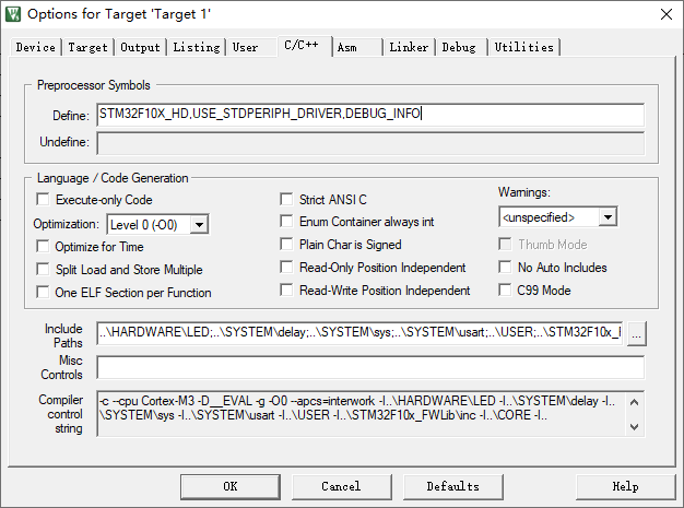
Developing STM32 program based on C + +
The development IDE is Keil V5. The development environment supports C + + compilation. In order to simplify the development difficulty, the program code is written based on C + +. For details on how to develop STM32 program based on C + +, see: STM32 C + + serial communication
Serial port printing is convenient for debugging
A major difficulty in embedded development is the high difficulty of debugging. Generally, the current hardware operation status will be obtained through serial port printing, and then the code execution will be judged. The serial port printing code file Mlog used this time H as follows:
#ifndef MLOG_H_
#define MLOG_H_

#include "usart.h"

#ifndef DEBUG_INFO
#define DEBUG_INFO
#endif

#ifdef DEBUG_INFO
#define user_main_printf(format, ...) 	USARTx_printf(USART1, format "\r\n", ##__VA_ARGS__)
#define user_main_info(format, ...) 		USARTx_printf(USART1, "[INFO] [%s@%s,%d] " format "\r\n", __FILE__, __func__, __LINE__, ##__VA_ARGS__);
#define user_main_debug(format, ...)    USARTx_printf(USART1, "[DEBUG] [%s@%s,%d] " format "\r\n", __FILE__, __func__, __LINE__, ##__VA_ARGS__)
#define user_main_error(format, ...) 		USARTx_printf(USART1, "[ERROR] [%s@%s,%d] " format "\r\n", __FILE__, __func__, __LINE__, ##__VA_ARGS__)
#else
#define user_main_printf(format, ...)
#define user_main_info(format, ...)
#define user_main_debug(format, ...)
#define user_main_error(format, ...)
#endif

#endif
Predefined macros can be added in the IDE. For details, see:
code implementation
USART and RS485 communication
usart.h, usart.c, rs485.h, rs485.c comes from the punctual atomic communication code
Steering gear communication protocol encapsulation
Encapsulate the steering gear communication protocol in the Servo class, as shown below:
// servo.h
#include "stdio.h"
#include "sys.h"
#include "delay.h"
#include "usart.h"
#include "mLog.h"
#include "rs485.h"

#define REC_BUFFER_LEN 32
#define SERVO_MAX_PARAMS (REC_BUFFER_LEN - 5)

#define REC_WAIT_START_US    75
#define REC_WAIT_PARAMS_US   (SERVO_MAX_PARAMS * 5)
#define REC_WAIT_MAX_RETRIES 200

#define SERVO_INSTRUCTION_ERROR   (1 << 6)
#define SERVO_OVERLOAD_ERROR      (1 << 5)
#define SERVO_CHECKSUM_ERROR      (1 << 4)
#define SERVO_RANGE_ERROR         (1 << 3)
#define SERVO_OVERHEAT_ERROR      (1 << 2)
#define SERVO_ANGLE_LIMIT_ERROR   (1 << 1)
#define SERVO_INPUT_VOLTAGE_ERROR (1)


enum ServoCommand
{
    PING = 1,
    READ = 2,
    WRITE = 3
};

typedef struct ServoResponse
{
    uint8_t id;
    uint8_t length;
    uint8_t error;
    uint8_t params[SERVO_MAX_PARAMS];
    uint8_t checksum;
} ServoResponse;

class Servo{
	public:
		Servo(u8 servoID=1, u32 baudrate=57600){
			m_baudrate=baudrate;
			m_servoID=servoID;
			delay_init();
		}
		void OpenPort(){
			RS485_Init(m_baudrate);
		}
		bool pingServo ();
		bool setServoAngle (const int angle);
		bool getServoAngle (int *angle);
		int getTemperature();
	private:
		void sendServoCommand (const ServoCommand commandByte,
		                       const uint8_t numParams,
		                       const uint8_t *params);

		bool getServoResponse ();
		bool getAndCheckResponse ();

		int getServoBytesAvailable ();

		void sendServoByte(uint8_t byte);
	private:
		u32 m_baudrate;
		u8 m_servoID;
		ServoResponse m_response;
};
// servo.cpp
// from control table
#define RETURN_DELAY 0x05
#define BLINK_CONDITIONS 0x11
#define SHUTDOWN_CONDITIONS 0x12
#define TORQUE 0x22
#define MAX_SPEED 0x20
#define CURRENT_SPEED 0x26
#define GOAL_ANGLE 0x1e
#define CURRENT_ANGLE 0x24
#define TEMPRETURE 0x2b
// response location
#define SERVO_ID_POS 2
#define SERVO_LEN_POS 3
#define SERVO_ERROR_POS 4
#define SERVO_PARAM_POS 5
// public
// ping a servo, returns true if we get back the expected values
bool Servo::pingServo ()
{
sendServoCommand (PING, 0, 0);
if (!getAndCheckResponse ())
return false;
return true;
}
bool Servo::setServoAngle (const int angle)
{
if (angle < 0 || angle > 0xfff)
return false;
const uint8_t highByte = (uint8_t)((angle >> 8) & 0xff);
const uint8_t lowByte = (uint8_t)(angle & 0xff);
const uint8_t params[3] = {GOAL_ANGLE,
lowByte,
highByte};
sendServoCommand (WRITE, 3, params);
if (!getAndCheckResponse ())
return false;
return true;
}
bool Servo::getServoAngle (int *angle)
{
const uint8_t params[2] = {CURRENT_ANGLE,
2};
sendServoCommand (READ, 2, params);
if (!getAndCheckResponse ())
return false;
uint16_t angleValue = m_response.params[1];
angleValue <<= 8;
angleValue |= m_response.params[0];
*angle = angleValue;
return true;
}
int Servo::getTemperature()
{
const uint8_t params[2] = {TEMPRETURE,
0x01};
sendServoCommand(READ, 2, params);
if (!getAndCheckResponse ())
return -1;
int tempreture=m_response.params[0];
return tempreture;
}
// private
void sendServoCommand (const ServoCommand commandByte,
const uint8_t numParams,
const uint8_t *params);
{
sendServoByte (0xff);
sendServoByte (0xff); // command header
sendServoByte (m_servoId); // servo ID
uint8_t checksum = m_servoId;
sendServoByte (numParams + 2); // number of following bytes
sendServoByte ((uint8_t)commandByte); // command
checksum += numParams + 2 + commandByte;
for (uint8_t i = 0; i < numParams; i++)
{
sendServoByte (params[i]); // parameters
checksum += params[i];
}
sendServoByte (~checksum); // checksum
RS485_RX_CNT=0; // Clear receive cache
// **import * * avoid interference between two serial port interrupts. Open USART2 serial port receiving interrupt and close USART1 serial port receiving interrupt
DisableUsart1RXIT();
}
bool Servo::getServoResponse ()
{
uint8_t retries = 0;
uint8_t res[REC_BUFFER_LEN];
uint8_t len;
while (getServoBytesAvailable() < 4)
{
retries++;
if (retries > REC_WAIT_MAX_RETRIES)
{
user_main_error("Too many retries at start");
return false;
}
delay_ms (REC_WAIT_START_US); // delay_us
}
retries = 0;
RS485_Receive_Data(res, &len);
m_response.id = res[SERVO_ID_POS];
m_response.length = res[SERVO_LEN_POS];
if (m_response.length > SERVO_MAX_PARAMS)
{
user_main_error("Response length too big: %d", (int)m_response.length);
return false;
}
if(len-SERVO_LEN_POS < m_response.length-1) // -1 or 0
{
user_main_error("Too many retries waiting for params, got %d of %d params", getServoBytesAvailable(), m_response.length);
return false;
}
m_response.error = res[SERVO_ERROR_POS];
for (uint8_t i = 0; i < m_response.length - 2; i++)
m_response.params[i] = res[SERVO_PARAM_POS+i];
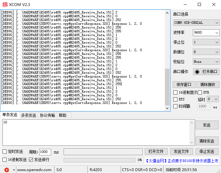
user_main_debug("Response %d, %d, %d", (int)m_response.id, (int)m_response.length, (int)m_response.error);
for (uint8_t i = 0; i < m_response.length - 2; i++)
user_main_debug("%d", m_response.params[i]);
uint8_t calcChecksum = m_response.id + m_response.length + m_response.error;
for (uint8_t i = 0; i < m_response.length - 2; i++)
calcChecksum += m_response.params[i];
calcChecksum = ~calcChecksum;
const uint8_t recChecksum = res[len-1];
if (calcChecksum != recChecksum)
{
user_main_error("Checksum mismatch: %d calculated, %d received", calcChecksum, recChecksum);
return false;
}
return true;
}
bool Servo::getAndCheckResponse ()
{
if (!getServoResponse())
{
user_main_error("Servo error: Servo %d did not respond correctly or at all", (int)m_servoId);
return false;
}
if (m_response.id != m_servoId)
{
user_main_error("Servo error: Response ID %d does not match command ID %d", (int)m_response.id, m_servoId);
return false;
}
if (m_response.error != 0)
{
user_main_error("Servo error: Response error code was nonzero (%d)", (int)m_response.error);
return false;
}
return true;
}
int Servo::getServoBytesAvailable ()
{
return RS485_RX_CNT;
}
void Servo::sendServoByte (uint8_t byte)
{
RS485_Send_Data(&byte, 1);
}
// main.cpp
void ShowResponse(){
	for(int i=0;i<RS485_RX_CNT;i++){
			user_main_debug("%d", RS485_RX_BUF[i]);
	}
}

int main(void)
{
	delay_init();
	NVIC_Configuration();
	uart_init(9600);	 				// USART1

	DisableUsart1RXIT();
	Servo servo;
	servo.OpenPort();

	bool bflag=servo.pingServo();
	if(bflag){
		DisableUsart2RXIT();
		ShowResponse();
		delay_ms(1000);
		DisableUsart1RXIT();

 	while(1)
	{
		// TODO
  	}
}
Result verification
important
Since it involves opening two USART receiving interrupts at the same time, the problem of interrupt nesting may occur, and an interrupt processing function is interrupted by an interrupt processing function, resulting in a BUG of incomplete data reception. To avoid this situation, two processing functions are added as follows:
// Disable Usart1RXIT Enable Usart2RXIT
void DisableUsart1RXIT()
{
	USART_ITConfig(USART1,USART_IT_RXNE,DISABLE);
	USART_ITConfig(USART2,USART_IT_RXNE,ENABLE);
	USART_Cmd(USART2,ENABLE);
}

// Disable Usart2RXIT Enable Usart1RXIT
void DisableUsart2RXIT()
{
	USART_ITConfig(USART2,USART_IT_RXNE,DISABLE);
	USART_ITConfig(USART1,USART_IT_RXNE,ENABLE);
  USART_Cmd(USART1,ENABLE);
}
Before adding this code, the steering gear response signal will be received incompletely, which will cause communication failure!