catalogue
1. Erunk configuration between SW1 and SW2
2. Create VLANs, divide VLANs and trunk roads
7. Configure the ip address of R1, R2 and SW1 uplink
12.SW1 and SW2 air interface anti ring - Optimization
13. Experimental verification -- the whole network is accessible
preface
How to complete the experiment according to the experimental requirements?
Test requirements:
1. Reasonable allocation of Intranet IP address 172.16.0.0/16
2.SW1/2 backup each other
3.VRRP /STP /VLAN /TRUNK are used
4. All PC s obtain IP addresses through DHCP
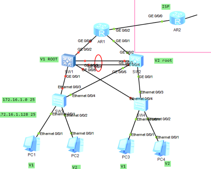
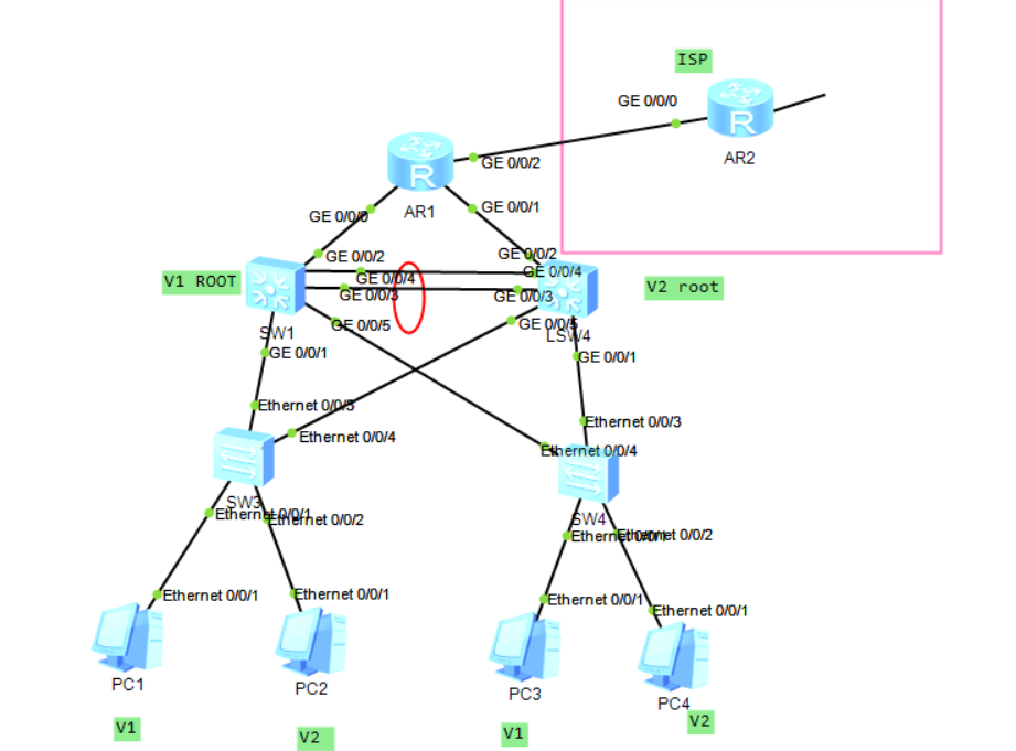
Network topology idea:
1. Topology design -- ip address planning
2. Implementation
0) environment deployment - building topology - all switching technologies
E-trunk # create vlan # divide vlan # trunk # STP SVI VRRP DHCP
1) Configure ip address - all nodes - routing
2) Routing -- network wide accessibility
3) Security policy - rule optimization
4) Testing
5) Troubleshooting
3. Maintenance
4. Upgrade
Experimental analysis:
1. Erunk configuration between SW1 and SW2
SW1:

[SW1]int Eth-Trunk  0  --establish Etrunk 0 Channel interface

Add physical interface to channel
[SW1]int g0/0/3
[SW1-GigabitEthernet0/0/3]eth-trunk 0

[SW1]int g0/0/4
[SW1-GigabitEthernet0/0/4]eth-trunk 0

SW2:

[SW2]int Eth-Trunk  0  --establish Etrunk 0 Channel interface

Add physical interface to channel
[SW2]int g0/0/3
[SW2-GigabitEthernet0/0/3]eth-trunk 0

[SW2]int g0/0/4
[SW2-GigabitEthernet0/0/4]eth-trunk 0
2. Create VLANs, divide VLANs and trunk roads
SW1:

[SW1]vlan 2   -----establish vlan

[SW1]port-group group-member g0/0/1 g0/0/5 Eth-Trunk 0   ----divide vlan
[SW1-port-group]port link-type trunk
[SW1-port-group]port trunk allow-pass vlan 2

SW2:

[SW2]vlan 2   -----establish vlan

[SW2]port-group group-member g0/0/1 g0/0/5 Eth-Trunk 0   ----divide vlan
[SW2-port-group]port link-type trunk
[SW2-port-group]port trunk allow-pass vlan 2

SW3:

[sw3]vlan 2   ---establish vlan

[sw3]port-group group-member e0/0/3 e0/0/4
[sw3-port-group]port link-type trunk  ------trunk pattern
[sw3-port-group]port trunk allow-pass vlan 2

[sw3]int e0/0/2          ----access pattern int
[sw3-Ethernet0/0/2]port link-type access
[sw3-Ethernet0/0/2]port default vlan 2

SW4:

[sw4]vlan 2   ---establish vlan

[sw4]port-group group-member e0/0/3 e0/0/4
[sw4-port-group]port link-type trunk  ------trunk pattern
[sw4-port-group]port trunk allow-pass vlan 2

[sw4]int e0/0/2          ----access pattern int
[sw4-Ethernet0/0/2]port link-type access
[sw4-Ethernet0/0/2]port default vlan 2
3. Configure STP
SW1:

[SW1]stp mode mstp ---Used by Huawei by default MSTP
[SW1]stp enable ---open stp

establish MST field
[SW1]stp region-configuration   --get into MST Domain configuration view
[SW1-mst-region]region-name a    ----Set the domain name. All devices should be in one domain
[SW1-mst-region]instance  1 vlan 1    --take VLAN Divide into examples according to requirements
[SW1-mst-region]instance  2 vlan 2
[SW1-mst-region]active region-configuration    --- activation MST Configuration of domain (this instruction must be configured)

SW2:

[SW2]stp mode mstp ---Used by Huawei by default MSTP
[SW2]stp enable ---open stp

establish MST field
[SW2]stp region-configuration   --get into MST Domain configuration view
[SW2-mst-region]region-name a    ----Set the domain name. All devices should be in one domain
[SW2-mst-region]instance  1 vlan 1    --take VLAN Divide into examples according to requirements
[SW2-mst-region]instance  2 vlan 2
[SW2-mst-region]active region-configuration    --- activation MST Configuration of domain (this instruction must be configured)

SW3:

[SW3]stp mode mstp ---Used by Huawei by default MSTP
[SW3]stp enable ---open stp

establish MST field
[SW3]stp region-configuration   --get into MST Domain configuration view
[SW3-mst-region]region-name a    ----Set the domain name. All devices should be in one domain
[SW3-mst-region]instance  1 vlan 1    --take VLAN Divide into examples according to requirements
[SW3-mst-region]instance  2 vlan 2
[SW3-mst-region]active region-configuration    --- activation MST Configuration of domain (this instruction must be configured)


SW4:

[SW4]stp mode mstp ---Used by Huawei by default MSTP
[SW4]stp enable ---open stp

establish MST field
[SW4]stp region-configuration   --get into MST Domain configuration view
[SW4-mst-region]region-name a    ----Set the domain name. All devices should be in one domain
[SW4-mst-region]instance  1 vlan 1    --take VLAN Divide into examples according to requirements
[SW4-mst-region]instance  2 vlan 2
[SW4-mst-region]active region-configuration    --- activation MST Configuration of domain (this instruction must be configured)
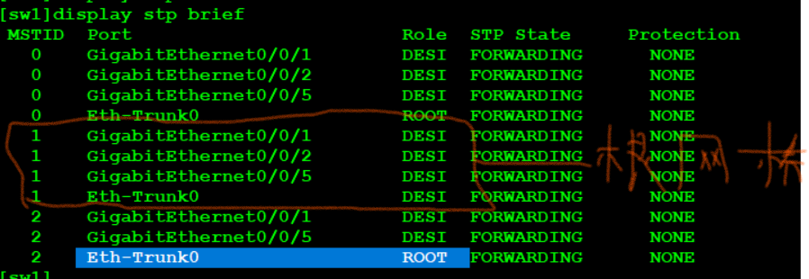
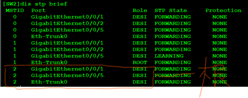
View the switch where the root bridge is located through the < SW1 > display STP brief. SW1 and SW2 should be the primary and backup roots of each other
SW1:

[SW1]stp instance 1 root primary
[SW1]stp instance 2 root secondary

SW2:

[SW2]stp instance 2 root primary
[SW2]stp instance 1 root secondary
View validation:
Optimization: -- speed up the switch ports connected to users
SW3:

[sw3]port-group group-member e0/0/1 e0/0/2
[sw3-port-group]stp edged-port enable

SW4:

[sw4]port-group group-member e0/0/1 e0/0/2
[sw4-port-group]stp edged-port enable
4. Configure SVI
SW1:

[sw1]int vlan 1
[sw1-Vlanif1]ip add 172.16.1.1 25

[sw1]int vlan 2
[sw1-Vlanif2]IP ADD 172.16.1.129 25

SW2:

[SW2]int vlan 1
[SW2-Vlanif1]ip add 172.16.1.2 25

[SW2-Vlanif1]int vlan 2
[SW2-Vlanif2]ip add 172.16.1.130 25
verification:
5. Configure VRRP
SW1:

[sw1]int vlan 1
[sw1-Vlanif1]vrrp vrid 1 virtual-ip 172.16.1.126
[sw1-Vlanif1]vrrp vrid 1 priority 105
[sw1-Vlanif1]vrrp vrid 1 track interface g0/0/2 reduced 6  ----Uplink tracking g0/0/2

[sw1]int vlan 2
[sw1-Vlanif2]vrrp vrid 1 virtual-ip 172.16.1.254

SW2:

[SW2]int vlan 1
[SW2-Vlanif1]vrrp vrid 1 virtual-ip 172.16.1.126

[SW2]int vlan 2
[SW2-Vlanif2]vrrp vrid 1 virtual-ip 172.16.1.254
[sw1-Vlanif2]vrrp vrid 1 priority 105
[SW2-Vlanif2]vrrp vrid  1 track interface g0/0/2 reduced 6
verification:
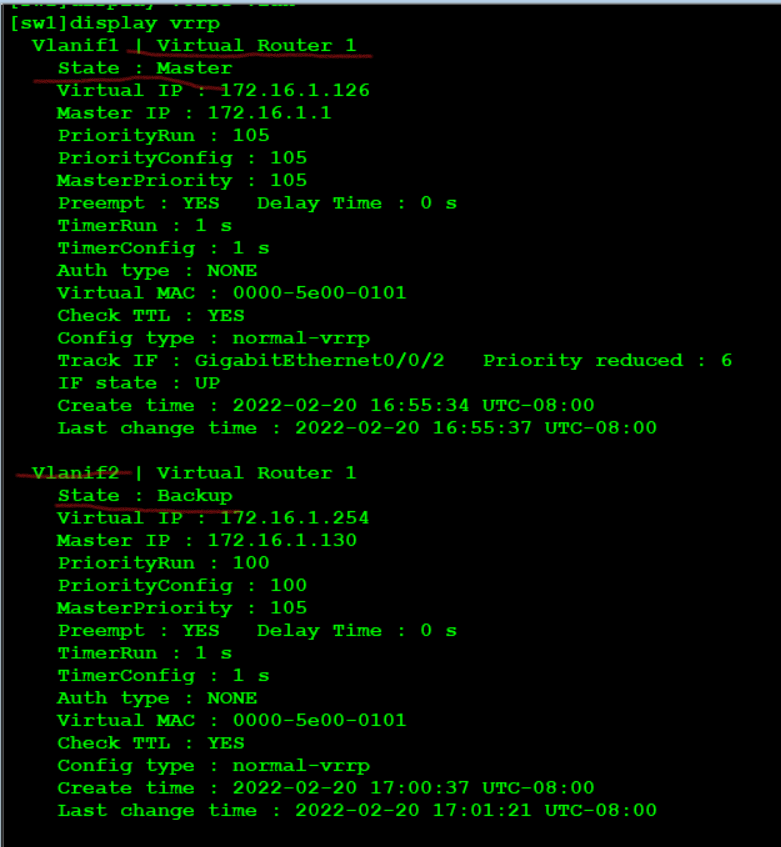
Viewing VRRP, you can see that vlan1 is master and vlan2 is backup in SW1
6. Configure DHCP
SW1:

[sw1]dhcp enable
[sw1]ip pool v1
[sw1-ip-pool-v1]network 172.16.1.0 mask 25
[sw1-ip-pool-v1]gateway-list 172.16.1.126
[sw1-ip-pool-v1]dns-list 114.114.114.114

[sw1]ip pool v2
[sw1-ip-pool-v2]network 172.16.1.128 mask 25
[sw1-ip-pool-v2]gateway-list 172.16.1.254
[sw1-ip-pool-v2]dns-list 114.114.114.114

[sw1]interface vlan 1
[sw1-Vlanif1]dhcp select global
[sw1-Vlanif1]int vlan 2
[sw1-Vlanif2]dhcp select global


ip pool v1
 gateway-list 172.16.1.126
 network 172.16.1.0 mask 255.255.255.128
 dns-list 114.114.114.114
ip pool v2
 gateway-list 172.16.1.254
 network 172.16.1.128 mask 255.255.255.128
 dns-list 114.114.114.114

SW2 and SW1 The configuration is the same as that of the address pool
7. Configure the ip address of R1, R2 and SW1 uplink
The switch of Huawei simulator cannot be configured after the routing function is enabled ip,So enable SVI simulation
SW1:

[sw1]vlan 99
[sw1]int vlan 99
[sw1-Vlanif99]ip add 172.16.0.2 30
[sw1]int g0/0/2
[sw1-GigabitEthernet0/0/2]port link-type access
[sw1-GigabitEthernet0/0/2]port default vlan 99

SW2:

[sw2]vlan 99
[sw2]int vlan 99
[sw2-Vlanif99]ip add 172.16.0.6 30
[sw2]int g0/0/2
[sw2-GigabitEthernet0/0/2]port link-type access
[sw2-GigabitEthernet0/0/2]port default vlan 99

R1:

[R1]int g0/0/0
[R1-GigabitEthernet0/0/0]ip add 172.16.0.1 30

[R1]int g0/0/2
[R1-GigabitEthernet0/0/2]ip add 12.1.1.1 24

[R1-GigabitEthernet0/0/2]int g0/0/1
[R1-GigabitEthernet0/0/1]ip add 172.16.0.5 30

ISP:

[R2]int g0/0/0
[R2-GigabitEthernet0/0/0]ip add 12.1.1.2 24

[R2]int LoopBack 0
[R2-LoopBack0]ip add 2.2.2.2 24
8. Configure OSPF routing
Method 1: R1 writes a route to the vlan below, the aggregation layer switch writes two defaults, and makes NAT on the R1 interface
Method 2: run OSPF in the aggregation layer and core layer - because OSPF does not support interface summary, two areas are required
sw1:

#
ospf 1 router-id 11.11.11.11
 area 0.0.0.0
  network 172.16.0.2 0.0.0.0
 area 0.0.0.1
  network 172.16.1.1 0.0.0.0
  network 172.16.1.129 0.0.0.0

SW2;

#
ospf 1 router-id 12.12.12.12
 area 0.0.0.0
  network 172.16.0.6 0.0.0.0
 area 0.0.0.1
  network 172.16.1.2 0.0.0.0
  network 172.16.1.130 0.0.0.0

R1:
#
ospf 1 router-id 1.1.1.1
 area 0.0.0.0
  network 12.1.1.1 0.0.0.0
  network 172.16.0.1 0.0.0.0
  network 172.16.0.5 0.0.0.0
9. Configure silent interface
Since the svi interface will send hello packets to each trunk every 10s to build neighbors, if the number of svi is too large, it will affect the trunk, so the interface needs to be silent
SW1:

#
ospf 1 router-id 11.11.11.11
 silent-interface all   ----When the number of interfaces is large, all interfaces can be turned on again
 undo silent-interface GigabitEthernet0/0/2
 undo silent-interface Eth-Trunk0
 undo silent-interface Vlanif1
 undo silent-interface Vlanif99

SW2:

#
ospf 1 router-id 12.12.12.12
 silent-interface GigabitEthernet0/0/1
 silent-interface GigabitEthernet0/0/5
 silent-interface Vlanif2
10. Summary
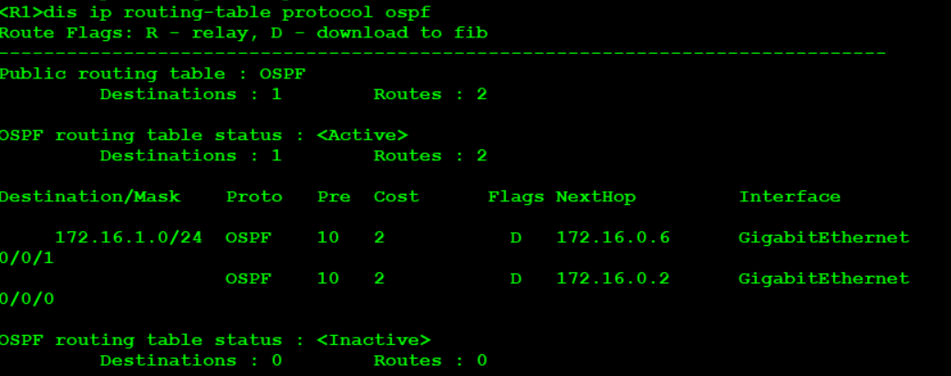
Check the R1 routing table and find that the following routes have been sent, which needs to be summarized
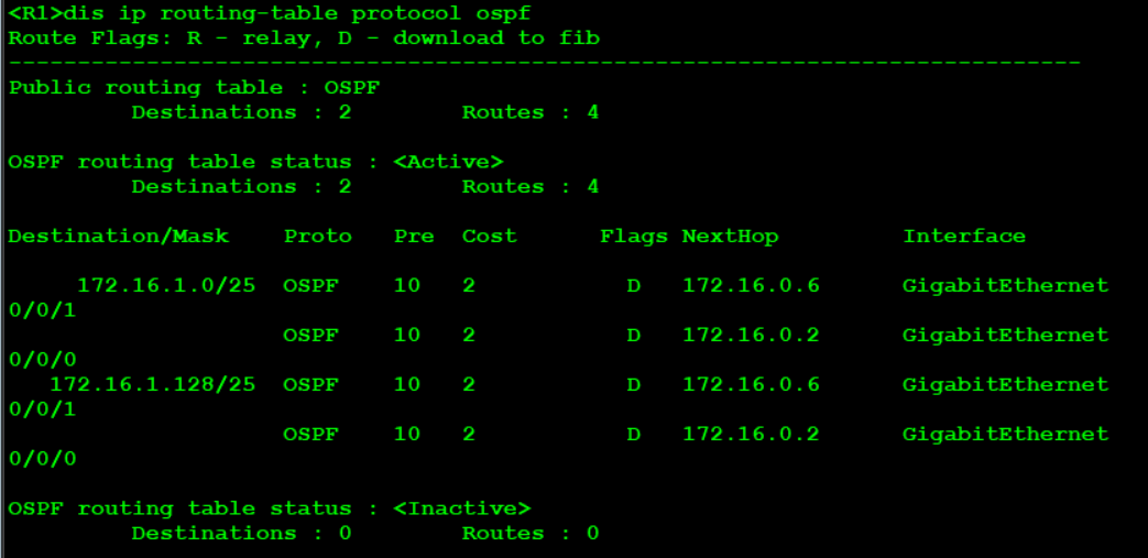
SW1:

[sw1]ospf 1
[sw1-ospf-1]area 1
[sw1-ospf-1-area-0.0.0.1]abr-summary  172.16.1.0 255.255.255.0

SW2:

[sw1]ospf 1
[sw1-ospf-1]area 1
[sw1-ospf-1-area-0.0.0.1]abr-summary  172.16.1.0 255.255.255.0
Check again and find that the R1 routing table has been load balanced
11.R1 default, NAT
R1:

[R1]ip route-static 0.0.0.0 0 12.1.1.2 ----Default point to operator
[R1]ospf 1
[R1-ospf-1]default-route-advertise   ---take ospf Announce to the aggregation layer switch below


[R1]acl 2000
[R1-acl-basic-2000]rule permit source 172.16.0.0 0.0.255.255

[R1-acl-basic-2000]int  g0/0/2
[R1-GigabitEthernet0/0/2]nat outbound 2000
12.SW1 and SW2 air interface anti ring - Optimization
SW1:

[sw1]ip route-static 172.16.1.0 24 NULL 0

SW2:

[sw2]ip route-static 172.16.1.0 24 NULL 0
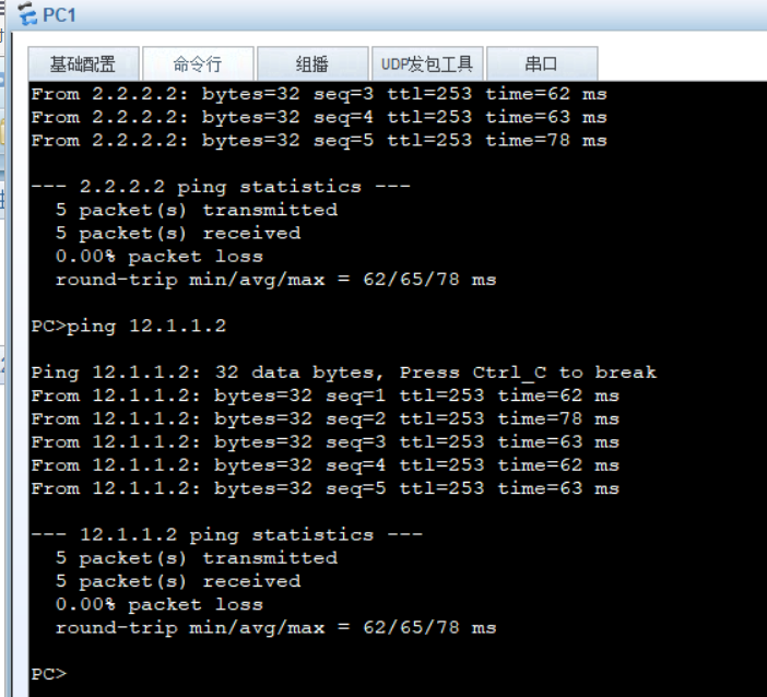
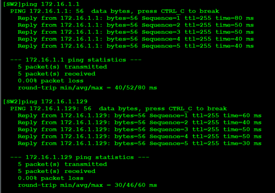
13. Experimental verification -- the whole network is accessible
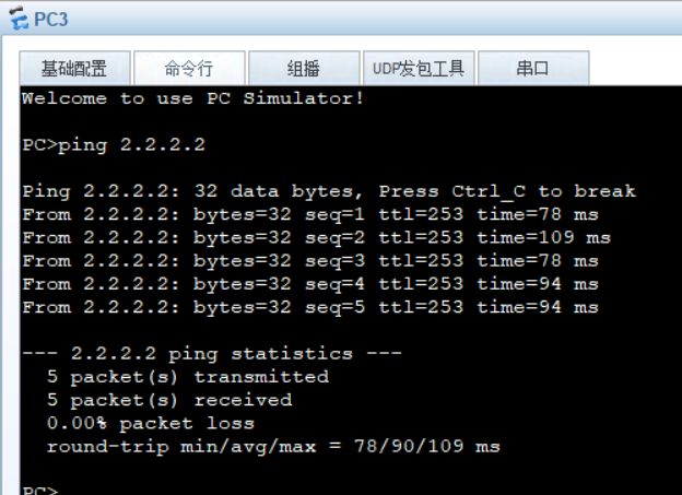
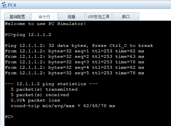
When SW1 fails, we test whether the PC can access the Internet normally