Accelerate the application expansion across GPUs within one computing node or across multiple GPUs.
CUDA provides a large number of functions to realize multi GPU Programming, including: managing multiple devices in one or more processes, using unified virtual addressing to directly access the memory of other devices, GPUDirect, and overlapping computing communication of multiple devices using streams and asynchronous functions. The contents to be mastered in this chapter include the following aspects:
Manage and execute the kernel on multiple GPU s;
Overlapping computing and communication on multiple GPU s;
Using streams and events to realize synchronous execution of multiple GPU s;
Expand CUDA aware MPI application on GPU acceleration cluster;
9.1 from one GPU to multiple GPUs
The most common reasons for adding multi GPU support are the following:
Size of problem domain: the existing data set is too large, and the memory size of a single GPU does not match it;
Throughput and efficiency: if a single GPU is suitable for processing tasks, you can increase the throughput of your application by using multiple GPUs to process multiple tasks concurrently.
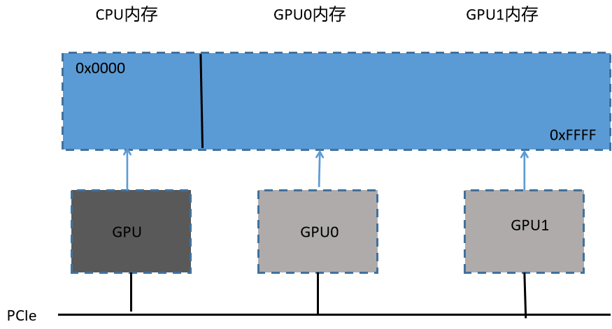
When using multiple GPUs to run applications, it is necessary to properly design the communication between GPUs. The efficiency of data transmission between GPUs depends on how GPUs are connected to one node and across clusters. There are two link modes in multi GPU system:
Multiple GPU s are connected to PCIe bus through a single node;
Connect the GPU in the cluster to the network;
Because the PCIe link is duplex, you can use CUDA API to map a path on the PCIe link to avoid bus competition and share data between GPU s.
In order to design a program that utilizes multiple GPUs, the workload needs to be distributed across devices. Depending on the application, this allocation results in two common modes of communication between GPUs:
There is no need for data exchange between problem partitions, so there is no data sharing among GPU s;
There is partial data exchange between problem partitions, and redundant data storage is required between GPU s.
The first mode is the most basic case. Each problem partition can run independently on different GPU s. To deal with these problems, you only need to know how to transfer data and call the kernel in multiple devices.
In the second mode, data exchange between GPU is necessary. We must consider how data can achieve optimal movement between devices. In short, avoid transferring data through the host memory (that is, if the data is copied to the host, it can only be copied to another GPU).
9.1.1 execution on multiple GPU s
The cudaGetDeviceCount() function determines the number of CUDA devices available in the system.
In a CUDA application that uses CUDA to work with multiple GPUs, you must explicitly specify which GPU is the target of all current CUDA operations. Use the cudaSetDevice(int id) function to set the current device. This function sets the device with identifier id as the current device. This function is not synchronized with other devices, so it is an offset call.
If the cudaSetDevice function is not explicitly called before the first CUDA API call, the current device will be automatically set to device 0
Once the current device is selected, all CUDA operations will be applied to that device:
Any device memory allocated from the main thread will be completely resident in the device;
Any host memory allocated by CUDA runtime function will have device related lifetime;
Any stream or event created by the host thread will be related to the device;
Any kernel started by the host thread will execute on the device;
You can use multiple GPU s in the following situations:
On a single CPU thread of a node;
On a multi CPU thread of a node
On a multi CPU process of a node;
On multi CPU processes of multiple nodes;
The following code accurately shows how to execute memory copy in the kernel and a single host thread:
for (int i = 0; i < ngpus; i++)
{
    cudaSetDevice(i);

    kernel<<<grid, block>>>(...);

    cudaMemcpyAsync();

}
Because the kernel startup and data transfer in the loop are asynchronous, control will soon return to the host thread after each call.
9.1.2 point to point communication
In devices with computing power of 2.0 or above, the kernel executing on 64 bit applications can directly access the global memory of any GPU connected to the same PCIe root node. If you want to do this, you must use CUDA peer-to-peer (P2P)API to realize direct communication between devices. Point to point communication requires cuda4 0 or later.
There are two modes supported by CUDA P2P API, which allow direct communication between GPU s:
Point to point access: directly load and store addresses between CUDA kernel and GPU;
Point to point transmission: directly copy data between GPU s;
In a system, if two GPU s are connected to different PCIe root nodes, direct peer-to-peer access is not allowed, and CUDA P2P API will notify you. The CUDA P2P API can still be used for point-to-point transmission between these devices, but the driver will transmit data transparently through the host memory rather than directly through the PCIe bus.
9.1.2.1 enable point-to-point access
Point to point access allows each GPU to connect to the same PCIe root node, making it directly reference the data stored in the memory of other GPU devices.
Use cudadeviccanaccesspeer() to check whether the device supports P2P. If the device can directly access the global memory of peer device peerDevice, the return value of the function variable is integer 1, otherwise it is 0;
Between two devices, point-to-point memory access must be explicitly enabled using cudaDeviceEnablePeerAccess() below. This function allows peer-to-peer access from the current device to peerDevice. The access authorized by this function is one-way.
Peer to peer access remains enabled until it is explicitly disabled by cudaDeviceDisablePeerAccess().
32-bit applications do not support point-to-point access.
9.1.2.2 peer to peer memory replication
After peer-to-peer access is enabled between two devices, the data on the device can be copied asynchronously using cudaMemcpyPeerAsync(). This function transfers data from the device's srcDev device to the device of the device dstDev. If srcDev and dstDev share the same PCIe root node, the data transmission is performed along the shortest path of PCIe and does not need to be transferred through the host memory.
9.1.3 synchronization between multiple GPU s
Each device is associated with a single event. The typical workflow of using streams and events in multi GPU applications is as follows:
1. Select the GPU set that this application will use;
2. Create streams and events for each device;
3. Allocate equipment resources for each equipment; (e.g. device memory)
4. Start the task on each GPU through the flow; (data transfer or kernel execution)
5. Use flow and event to query and wait for task completion;
6. Empty the resources of all devices;
The kernel can only be started in the stream if the device associated with the stream is the current device. Events can only be recorded in the flow if the device associated with the flow is the current device.
Memory copies can be made in any stream at any time, no matter what device the stream is related to or what the current device is. You can query or synchronize streams or events even if they are not related to the current device.
9.2 subdivision calculation among multiple GPU s
9.2.1 allocating memory on multiple devices
// Before assigning tasks from the host to multiple devices, you first need to determine how many GPU s are available in the current system:
int ngpus;
cudaGetDeviceCount(&npus);
printf("CUDA-capable devices: %i\n", ngpus);

// Declare the host memory, device memory, streams, and events required by multiple devices
float* d_A[ngpus], * d_B[ngpus], * d_C[ngpus];
float* h_A[ngpus], * h_B[ngpus], * h_C[ngpus];
cudaStream_t streams[ngpus];

// Data size allocated per device
int size = 1 << 24;
int iSize = size / ngpus;

size_t iBytes = iSize * sizeof(float);

// Allocate host and device memory, and create streams
for (int i = 0; i < ngpus; i++)
{
    cudaSetDevice(i);

    cudaMalloc((void**)&d_A[i], iBytes);
    cudaMalloc((void**)&d_B[i], iBytes);
    cudaMalloc((void**)&d_C[i], iBytes);

    // Lock page memory is allocated for asynchronous data transfer between the device and the host
    cudaMallocHost((void**)&h_A[i], iBytes);
    cudaMallocHost((void**)&h_B[i], iBytes);
    cudaMallocHost((void**)&hostRef[i], iBytes);
    cudaMallocHost((void**)&gpuRef[i], iBytes);

    cudaStreamCreate(&streams[i]);
}
9.2.2 single host thread assignment
// Initializes the state of the host array for each device before the inter device allocation operation
for (int i = 0; i < ngpus; i++)
{
    cudaSetDevice(i);
    initial(h_A[i], iSize);
    initial(h_B[i], iSize);
}

// Distribute data and calculations across multiple devices
for (int i = 0; i < ngpus; i++)
{
    cudaSetDevice(i);

    cudaMemcpyAsync(d_A[i], h_A[i], iBytes, cudaMemcpyHostToDevice, streams[i]);
    cudaMemcpyAsync(d_B[i], h_B[i], iBytes, cudaMemcpyHostToDevice, streams[i]);

    iKernel<<<grid, block, 0, streams[i]>>>(d_A[i], d_B[i], d_C[i], iSize);

    cudaMemcpyAsync(gpuRef[i], d_C[i], iBytes, cudaMemcpyDeviceToHost, stream[i]);
}

cudaDeviceSynchronize();
This loop traverses multiple GPU s and asynchronously copies the input array for the device. Then operate iSize data elements in the desired stream to start the kernel. Finally, the device sends an asynchronous copy command to return the result from the kernel to the host. Because all elements are asynchronous, control is immediately returned to the host thread.
9.3 point to point communication on multiple GPU s
In this section, three cases will be tested;
One way memory replication between two GPU s;
Bidirectional memory replication between two GPU s;
Access to peer device memory in kernel;
9.3.1 realize point-to-point access
First, bidirectional point-to-point access must be enabled for all devices. The code is as follows;
// Enable bidirectional point-to-point access
inline void enableP2P(int ngpus)
{
    for (int i = 0; i < ngpus; i++)
    {
        cudaSetDevice(i)
        for (int j = 0; j < ngpus; j++)
        {
            if (i == j)
                continue;

            int peer_access_available = 0;

            cudaDeviceCanAccessPeer(&peer_access_available, i, j);

            if (peer_access_avilable)
            {
                cudaDeviceEnablePeerAccess(j, i);
                printf(" > GP%d enbled direct access to GPU%d\n", i, j);
            }
            else
                printf("(%d, %d)\n", i, j);
        }
    }
}
The function enbleP2P traverses all device pairs (i, j). If point-to-point access is supported, use the cudaDeviceEnablePeerAccess function to enable bidirectional point-to-point access.
9.3.2 point to point memory replication
The most likely reason why point-to-point access cannot be enabled is that they are not connected to the same PCIe root node. If point-to-point access is not supported between two GPU s, point-to-point memory replication between the two devices will be transferred through the host memory, thus reducing its performance.
After point-to-point access is enabled, the following code performs ping pong synchronous memory replication between the two devices for 100 times.
// ping-pong undirectional gmem copy
cudaEventRecord(start, 0);
for (int i = 0; u < 100; i++)
{
    if (i % 2 == 0)
        cudaMemcpy(d_src[1], drc[0], iBytes, cudaMemcpyDeviceToHost);
    else
        cudaMemcpy(d_src[0], drc[1], iBytes, cudaMemcpyDeviceToHost);
}
Note that the device is not specified before memory replication, because memory replication across devices does not need to explicitly set the current device. If a device is specified before memory replication, its behavior will not be affected.
To measure the performance of data transmission between devices, you need to record the start and stop events on the same device and include ping pong memory replication. Then, use cudaEventElapsedTime to calculate the time consumed between the two events.
// ping-pong undirectional gmem copy
cudaEventRecord(start, 0);
for (int i = 0; u < 100; i++)
{
    if (i % 2 == 0)
        cudaMemcpy(d_src[1], drc[0], iBytes, cudaMemcpyDeviceToHost);
    else
        cudaMemcpy(d_src[0], drc[1], iBytes, cudaMemcpyDeviceToHost);
}

cudaEventRecord(start, 0);
for (int i = 0; u < 100; i++)
{
...
}
cudaSetDevice(0);
cudaEventRecord(stop, 0);
cudaEventSynchronize(stop);

float elapsed_time_ms;
cudaEventElapsedTime(&elapsed_time_ms, start, stop);

elapsed_time_ms /= 100;
printf("Ping-pong unidirectional cudaMemcpy: \t\t %8.2f ms", elapsed_time_ms);
printf("performance: %8.2f GB/s\n", (float)iBytes / (elapsed_time_ms * 1e6f));
Because the PCIe Bus supports full duplex channels between any two endpoints, asynchronous replication functions can also be used for bidirectional and point-to-point memory replication.
// bidirectional asynchronous gmem copy
for (int i = 0; u < 100; i++)
{
    if (i % 2 == 0)
        cudaMemcpyAsync(d_src[1], drc[0], iBytes, cudaMemcpyDeviceToHost);
    else
        cudaMemcpyAsync(d_rcv[0], drcv[1], iBytes, cudaMemcpyDeviceToHost);
}
Note that since the PCIe bus is used in two directions at a time, the bandwidth obtained is doubled.
9.3.3 point to point memory access for unified virtual addressing
The unified virtual addressing introduced in Chapter 4 is to map the CPU system memory and the global memory of the device to a single virtual address space.
The combination of point-to-point CUDA} API and UVA can realize transparent access to the memory of any device. There is no need to manually manage separate memory caches or explicitly copy from host memory. The underlying system allows us to avoid performing these operations explicitly, thus simplifying the code. Please note that relying too much on UVA for peer-to-peer access will have a negative impact on performance.
The following code demonstrates how to check whether the device supports unified addressing:
int deviceId = 0;
cudaDeviceProp prop;
cudaGetDeviceProperties(&prop, deviceId);
printf("GPU%d: %s unified addressing\n", deviceId, prop.unifiedAddressing ? "supprots" : "dose not support");
In order to use UVA, the application must be compiled on a 64 bit architecture with a computing power of 2.0 and above, and the CUDA version is 4.0 or above. If point-to-point access and UVA are enabled at the same time, the kernel function executed on one device can release the pointer stored on another device.
The following code sets device 0 as the current device, and a kernel function uses pointer d_src[1] reads the global memory from device 1 and your pointer D through the global memory_ RCV [0] writes the result to the current device.
cudaSetDevice(0);
iKernel<<<grid, block>>>(d_rcv[0], d_src[1]);
cudaSetDevice(1);
iKernel<<<grid, block>>>(d_rcv[1], d_src[0]);
If the GPU is not connected to the same PCIe root node, or point-to-point access is disabled, the following error message appears:
GPU0 disable direct access to GPU0;
9.4 finite difference on multiple GPU s
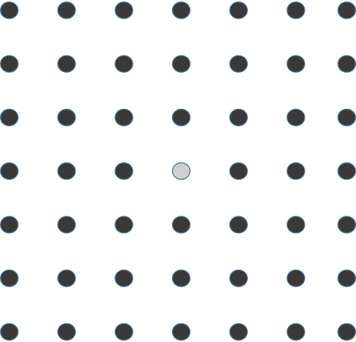
9.4.1 template calculation of two-dimensional wave equation
9.4.2 typical mode of multi GPU program
In order to accurately simulate the wave propagation through different media, a large amount of data is needed. However, the global memory of a single GPU does not have enough space to store the state of the simulation process. This requires data domain decomposition across multiple GPUs.
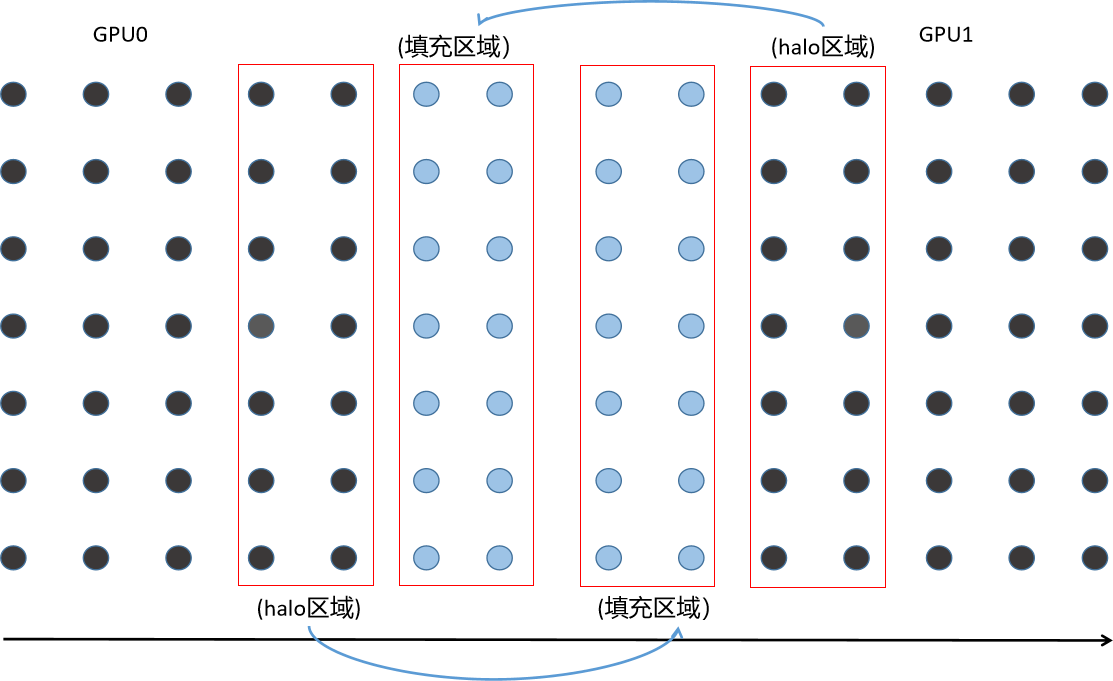
1. Calculating halo area and exchanging halo data using adjacent GPU s in a stream;
2. Calculate the internal area in different flows;
3. Conduct synchronous calculation on all equipment before the next cycle;
If two different streams are used, one for halo calculation and communication and the other for internal area calculation, step 1 can overlap step 2. If the calculation time required for internal calculation is longer than that required for halo operation, linear acceleration can be achieved by using multiple GPU s to hide the performance impact of halo communication.
The pseudo code for template calculation on two GPU s is as follows:
for (int istep = 0; istep < nsteps; istep++)
{
    for (int i = 0; i < 2; i++)
    {
        cudaSetDevice(i);
        2dfd_kernel<<<grid, block, 0, stream_halo[i]>>>(...);
    }

    cudaMemcpyAsync(..., cudaMemcpyDeviceToDevice, stream_halo[0]);
    cudaMemcpyAsync(..., cudaMemcpyDeviceToDevice, stream_halo[1]);

    for (int i = 0; i < 2; i++)
    {
        cudaSetDevice(i);
        2dfd_kernel<<<grid, block, 0, stream_internal[i]>>>(...);
    }

    for (int i = 0; i < 2; i++)
    {
        cudaSetDevice(i);
        cudaDeviceSynchronize();
    }
}
9.4.3 2D template calculation on multiple GPU s
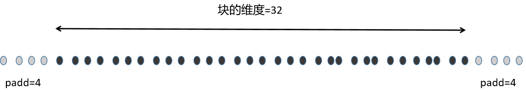
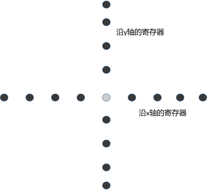
Because the latest 9 points need to be accessed to follow a new point, many points will share the input data. Therefore, using shared memory can reduce access to global memory. The usage of shared memory is equal to the size of protecting adjacent thread blocks, which are filled with 8 points. (4 points on the left and right)
The nine floating-point values used to store the y-axis template values are declared as a local array of kernel functions and therefore stored in registers. When loading elements along the y-axis before and after the current element, the registers used are much like shared memory used to reduce redundant access.
// The complete kernel code of 2D template calculation is as follows:
__global__ void kernel_2dfd(float* g_ul, float* g_u2, const int nx, const int iStart, const int iEnd)
{
    // global thread index to row index
    unsigned int ix = blockIdx.x * blockDim.x + threadIdx.x;

    // smem idx for current point
    unsigned int stx = threadIdx.x + NPAD;

    // global index with offset to start line
    unsigned int idx = ix + iStart * nx;

    // declare the shared memory for x dimension
    __shared__ float line[BDIMX + NPAD * 2];

    // a coefficient related to physical properties
    const int alpha = 0.12f;

    // declare nine registers for y value;
    float yval[NPAD * 2 + 1];
    for (int i = 0; i < NPAD * 2; i++)
        yval[i] = g_u2(idx + (i - NPAD) * nx);

    // offset from current point to yval[8]
    int iSkip = NPAD * nx;

    #pragma unroll 9
    for (int iy = 0; iy < iEnd; iy++)
    {
        // set yval[8] here
        yval[8] = g_u2(idx + iSkip);

        // read halo part in x dimension: both left and right
        if (threadIdx.x < NPAD)
        {
            line[threadIdx.x] = g_u2[idx - NPAD];
            line[stx + BDIMX] = g_u2[idx + BDIMX];
        }

        // current point
        line[stx] = yval[4];

        __syncthreads();

        // fd operator: 8th order in space and 2nd order in time
        if ((ix > NPAD) && (ix < nx-NPAD))
        {
            // update center point
            float temp = coef[0] * stx * 2.0f;

            // 8th order in x dimension
            #pragma unroll
            for (int d = 1; d <= 4; d++)
                temp += coef[d] * (line[stx + d] + line[stx - d]);

            // 8th order in y dimension
            #pragma unroll
            for (int d = 1; d <= 4; d++)
                temp += coef[d] * (yval[stx + d] + yval[stx - d]);

            // 2th order in time dimension
            g_u1[idx] = yval[4] + yval[4] - g_u1[idx] + alpha * temp;
        }

        // advance on yval[]
        #pragma unroll 8
        for (int i = 0; i < 8; i++) yval[i] = yval[i + 1];

        // update global idx
        idx += nx;

        // synchronize for next step
        __syncthreads();

    }

}
9.4.4 overlapping calculation and communication
Because each computing device is arranged in halo and stream_ In the halo flow, the calculation of the internal area is arranged in the stream of each device_ Internal flow, so computing and communication on this two-dimensional template can overlap.
// add a disturbance onto gpu0 on the first time step
cudaSetDevice(0);
kernel_add_wavelet<<<grid, block>>>(d_u2[0], 20.0, nx, iny, ngpus);

// for each time step
for (int iStep = 0; iStep < nSteps; iStep++)
{
    if (istep == 0)
    {
        cudaSetDevice(gpuid[0]);
        kernel_add_wavelet<<<grid, block>>>(d_u2[0], 20.0, nx, iny, ngpus);
    }

    // update halo and internal asynchronously
    for (int i = 0; i < ngpus; i++)
    {
        cudaSetDevice(i);

        // compute the halo region values in the halo stream
        kernel_2dfd<<<grid, block, 0, stream_halo[i]>>>(d_u1[i], d_u2[i], nx, haloStart[i], haloEnd[i]);

        // compute the internal region values in the internal stream
        kernel_2dfd<<<grid, block, 0, stream_intern[i]>>>(d_u1[i], d_u2[i], nx, bodyStart[i], bodyEnd[i]);
    }

    // exchange halos in the halo stream
    if (ngpus > 1)
    {
        cudaMemcpyAsync(d_u1[1] + dst_skip[0], d_u1[0] + src_skip[0], iexchange, cudaMemcpyDeviceToDevice, stream_halo[0]);
        cudaMemcpyAsync(d_u1[0] + dst_skip[1], d_u1[1] + src_skip[1], iexchange, cudaMemcpyDeviceToDevice, stream_halo[0]);
    }

    // synchronize for the next step
    for (int i = 0; i < ngpus; i++)
    {
        cudaSetDevice(i);
        cudaDeviceSynchronize();

        // swap global memory pointers
        float* tempu0 = d_u1[i];
        d_u1[i] = d_u2[i];
        d_u2[i] = tempu0;
    }
}
9.5 extending applications across GPU clusters
Compared with homogeneous systems, GPU accelerated cluster is recognized to greatly improve the performance and save the power consumption of computing intensive applications.
MPI and CUDA are fully compatible. There are two ways to implement MPI that supports moving data on different nodes between GPU s: traditional MPI and CUDA aware MPI.
In traditional MPI, only the contents of host memory can be transmitted directly through MPI function. Before MPI transfers data to another node, the contents of GPU memory must be copied back to host memory using CUDA API.
In CUDA aware MPI, the contents in GPU memory can be directly transferred to MPI function without transmitting data in host memory.
9.5.1 CPU to CPU data transmission
Generally speaking, MPI procedure includes four steps:
1. Initialize MPI environment;
2. Use blocking or non blocking MPI functions to transfer messages between processes of different nodes;
3. Cross node synchronization;
4. Clean up MPI environment
9.5.1.1 realize MPI communication between nodes
The following code shows a simple MPI program framework:
int main(int argc, char* argv[])
{
    // initialize the MPI enviroment
    int rank, nprocs;
    MPI_Init(&argc, &argv);
    MPI_Comm_size(MPI_COMM_WORLD, &nproc);
    MPI_Comm_rank(MPI_COMM_WORLD, &rank);

    // transmit message with MPI calls
    MPI_Send(sbuf, size, MPI_CHAR, 1, 100, MPI_COMM_WORLD);
    MPI_Recv(rbuf, size, MPI_CHAR, 0, 100, MPI_COMM_WORLD, &reqstat);

    // synchronize
    MPI_Barrier(MPI_COMM_WORLD);

    // clean up the MPI enviroment
    MPI_Finalize();

    return EXIT_SUCCESS;
}
char* s_buf = (char* )malloc(MYBUFSIZE);
char* r_buf = (char* )malloc(MYBUFSIZE);
// if this is the first MPI process
if (rank == 0)
{
for (int i = 0; i < nRepeat; i++)
{
// Asynchronously receive size bytes from other_proc into rbuf
MPI_Irecv(rbuf, size, MPI_CHAR, other_proc, 10, MPI_COMM_WORLD, &recv_request);
// Asynchronously send size bytes to other_proc from itself
MPI_Isend(sbuf, size, MPI_CHAR, other_proc. 100, MPI_COMM_WORLD, &send_request);
// wait for the send to complete
NPI_Waitall(1, &send_request, &reqstat);
// wait for the receive to complete
NPI_Waitall(1, &recv_request, &reqstat);
}
}
else if(rank == 1)
{
for (int i = 0; i < nRepeat; i++)
{
// Asynchronously receive size bytes from other_proc into rbuf
MPI_Irecv(rbuf, size, MPI_CHAR, other_proc, 100, MPI_COMM_WORLD, &recv_request);
// Asynchronously send size bytes to other_proc from itself
MPI_Isend(sbuf, size, MPI_CHAR, other_proc. 10, MPI_COMM_WORLD, &send_request);
// wait for the send to complete
NPI_Waitall(1, &send_request, &reqstat);
// wait for the receive to complete
NPI_Waitall(1, &recv_request, &reqstat);
}
}
9.5.1.2 CPU affinity
Under the control of the operating system, a process or thread will pause or move to a new core. This behavior will result in poor data locality, which will have a negative impact on performance. Therefore, binding a process or thread to a single CPU core (or a group of adjacent CPU cores) can help improve host performance.
Restricting the execution of a process or thread on a specific CPU core is called CPU affinity.
MVAPICH2 provides a way to use MV2 at runtime_ ENABLE_ The affinity environment variable to set CPU affinity.
For single threaded or single process applications, enabling CPU affinity can prevent the operating system from moving processes or threads between processors, thus providing equal or better performance. On the other hand, when CPU affinity is disabled, the performance of multithreaded and multiprocessing applications may be improved.
9.5.2 using traditional MPI to transmit data between GPU and GPU
In order to simplify data exchange between GPUs and improve performance, MPI processes should be bound on each GPU of each node.
9.5.2.1 affinity within mpi-cuda program
Binding MPI processes in a specific GPU is called GPU affinity, which usually uses MPI_ The init function is performed before initializing the MPI environment.
You must first use the environment variables provided by the MPI library. MV2_COMM_WORLD_LOCAL_RANK. This local ID, also known as local rank, can bind an MPI process to a CUDA device.
int n_device;
int local_rank = atoi(getenv("MV2_COMM_WORLD_LOCAL_RANK"));
cudaGetDeviceCount(&n_device);
int device = local_rank % n_device;
cudaSetDevice(device);
...
MPI_Init(argc, argv);
However, if the environment variable MV2 is used for the first time_ ENABLE_ Affinity sets the CPU affinity of the MPI process, and then uses MV2_ COMM_ WORLD_ LOCAL_ If rank sets GPU affinity, there is no guarantee that the CPU running MPI process and the allocated GPU are the best combination. If they are not the best combination, the latency and bandwidth between host applications and device memory may become unsatisfactory. Therefore, the portable Hardware Locality package (hwloc) can be used to analyze the hardware topology of the node, and the CPU core where the MPI process is located and the GPU allocated to the MPI process are the best combination.
The following code uses the process MPI local rank to select a GPU. Then, for the selected GPU, use hwloc to determine the best CPU core to bind the process.
rank = atoi(getenv("MV2_COMM_WORLD_RANK"));
local_rank = atoi(getenv("MV2_COMM_WORLD_LOCAL_RANK"));

// load a full hardware topology of all PCI devices in this node
hwloc_topology_init(&topology);
hwloc_topology_set_flags(topology, HWLOC_TOPOLOGY_FLAG_WHOLE_IO);
hwloc_topology_load(topology);

// choose a GPU based on MPI local rank
cudaSetDevice(local_rank);
cudaGetDevice(&device);

// Iterate through all CPU cores that are physically close to the selected GPU
// this code evenly distributes processes across cores using local_rank
cpuset = hwloc_bitmap_alloc();
hwloc_cudart_get_device_cpuset(topology, device, cpuset);
match = 0;
hwloc_bitmap_foreach_begin(i, cpuset);
if (match == local_rank)
{
    cpu = i;
    break;
}
++match;
hwloc_bitmap_foreach_end();

// this process to selected GPU
onecpu = hwloc_bitmap_alloc();
hwloc_bitmap_set(onecpu, cpu);
hwloc_set_cpubind(topology, onecpu, 0);

// clean up
hwloc_bitmap_free(onecpu);
hwloc_bitmap_free(cpuset);
hwloc_topology_destory(topology);

gethostname(hostname, sizeof(hostname));
cpu = sched_getcpu();
printf("MPI rank %d using GPU %d and CPU %d on host %s\n", rank, device, cpu, hostname);
MPI_Init(&argc, &argv);
MPI_Comm_rank(MPI_COMM_WWORLD, &rank);
if (MPI_SUCCESS != MPI_Get_processor_name(procname, &length))
    strcpy(procname, "unnake");
9.5.2.2 use MPI to perform communication between GPU s
Once the MPI process is scheduled to a GPU through the cudaSetDevice function, the device memory and host fixed memory can be allocated to the current device:
char* h_src, *h_rcv;
cudaMallocHost((void**)&h_src, MYBUFSIZE);
cudaMallocHost((void**)&h_rcv, MYBUFSIZE);

char* d_src, d_rcv;
cudaMalloc((void**)&h_src, MYBUFSIZE);
cudaMalloc((void**)&h_rcv, MYBUFSIZE);
Bidirectional data transmission between two GPU s using traditional MPI can be performed in two steps:
First, copy the data from the device memory to the host memory;
Secondly, the MPI communication library is used to exchange the data in the host memory between MPI processes;
if (rank == 0)
{
    for (int i = 0; i < loop; i++)
    {
        cudaMemcpy(h_src, d_src, size, cudaMemcpyDeviceToHost);

        // bi-direction bandwidth
        MPI_Irecv(h_rcv, size, MPI_CHAR, other_proc, 10, MPI_COMM_WORLD, &recv_request);
        MPI_Isend(h_src, size, MPI_CHAR, other_proc, 100, MPI_COMM_WORLD, &send_request);

        MPI_Waitall(1, &recv_request, &reqstat);
        MPI_Waitall(1, &send_request, &reqstat);

        cudaMemcpy(d_rcv, h_rcv, size, cudaMemcpyHostToDevice);
    }
}
else
{
    for (int i = 0; i < loop; i++)
    {
        cudaMemcpy(h_src, d_src, size, cudaMemcpyDeviceToHost);

        // bi-direction bandwidth
        MPI_Irecv(h_rcv, size, MPI_CHAR, other_proc, 100, MPI_COMM_WORLD, &recv_request);
        MPI_Isend(h_src, size, MPI_CHAR, other_proc, 10, MPI_COMM_WORLD, &send_request);

        MPI_Waitall(1, &recv_request, &reqstat);
        MPI_Waitall(1, &send_request, &reqstat);

        cudaMemcpy(d_rcv, h_rcv, size, cudaMemcpyHostToDevice);
    }

}
Use mpicc - STD = C99 - 03 simplepp2p C -o simplepp2p compilation;
Use mpirun_sh -np 2 node01 node 02 ./simpleP2P starts MPI program;
9.5.3 data transmission from GPU to GPU using CUDA aware MPI
MVAPICH2 is also a CUDA aware MPI implementation. It supports GPU to GPU communication through standard MPI API. It can directly pass the pointer of device memory to MPI function (and avoid additional cudaMemcpy calls required by traditional MPI).
if (rank == 0)
{
    for (int i = 0; i < loop; i++)
    {
        // bi-direction bandwidth
        MPI_Irecv(d_rcv, size, MPI_CHAR, other_proc, 10, MPI_COMM_WORLD, &recv_request);
        MPI_Isend(d_src, size, MPI_CHAR, other_proc, 100, MPI_COMM_WORLD, &send_request);

        MPI_Waitall(1, &recv_request, &reqstat);
        MPI_Waitall(1, &send_request, &reqstat);
    }
}
else
{
    for (int i = 0; i < loop; i++)
    {
        // bi-direction bandwidth
        MPI_Irecv(d_rcv, size, MPI_CHAR, other_proc, 100, MPI_COMM_WORLD, &recv_request);
        MPI_Isend(d_src, size, MPI_CHAR, other_proc, 10, MPI_COMM_WORLD, &send_request);

        MPI_Waitall(1, &recv_request, &reqstat);
        MPI_Waitall(1, &send_request, &reqstat);
    }
}
After compilation, before starting the MPI program, you need to set the following environment variables to ensure that CUDA is enabled in MVAPICH2 to support export MV2_USE_CUDA=1;
You can also set the environment variable mpirun when the MPI program is called_ sh -np 2 node01 node 02 MV2_ USE_ CUDA-1 ./ simpleP2P;
9.5.4 use CUDA aware MPI for data transmission from GPU to GPU in the node
The same GPU can also be used to transfer data in the same cuda-aware node. If two GPUs are connected to the same PCIe bus, point-to-point transmission is automatically used.
9.5.5 resizing message blocks
By overlapping the communication between the host and the device and the communication between nodes to minimize the communication overhead, MVAPICH2 automatically divides a large amount of information from GPU memory into blocks. The block size can be MV2_ CUDA_ BLOCK_ Adjust the size environment variable. The default block size is 256KB. It can be set to 512KB, and the command is as follows;
mpirun_rsh -np2 node01 node02 MV2_USE_CUDA=1 MV2_CUDA_BLOCK_SIZE=524288 ./simpleP2P
The optimal block size depends on several factors, including interconnection bandwidth / delay, characteristics of GPU adapter, platform characteristics, and the memory size allowed by MPI function.
9.5.6 GPU to GPU data transmission using GPUDirect RADM Technology
NVIDIA's GPUDirect enables low latency communication between GPU and other devices on PCIe bus. Using GPUDirect, third-party network adapters and other devices can exchange data directly through the host based fixed memory area, which eliminates unnecessary host memory replication, and significantly improves the data transmission of applications running on multiple devices.
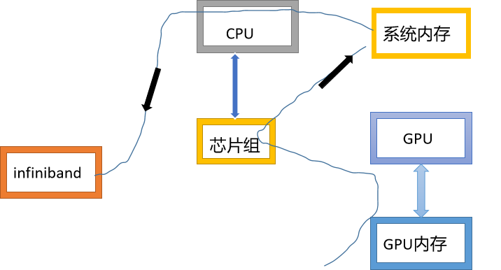
The first version of GPUDirect, and cuda3 1, which allows InfiniBand devices and GPU devices to share the same lock page buffer in CPU memory. The data is sent from the GPU of one node to the GPU of another node. The data is copied from the source GPU to the fixed and shared data buffer in the system memory, and then directly copied from the shared buffer to the buffer that can be accessed by other GPUs and matched with the destination node through InfiniBand interconnection.
The second version of GPUDirect, and cuda4 0, adding point-to-point API and unified virtual addressing support. These improvements improve the performance of single node multi GPU and provide programmer efficiency by eliminating the need to manage multiple pointers in different address spaces.
The third version of GPUDirect, and cuda5 0, adding remote direct memory access (RDMA) support. RDMA allows direct communication paths through InfiniBand. It uses standard PCIe adapters between GPUs of different cluster nodes. Using GPUDirect RAMD, communication between GPUs of two nodes can be performed without the participation of host processors. This reduces processor consumption and communication latency.
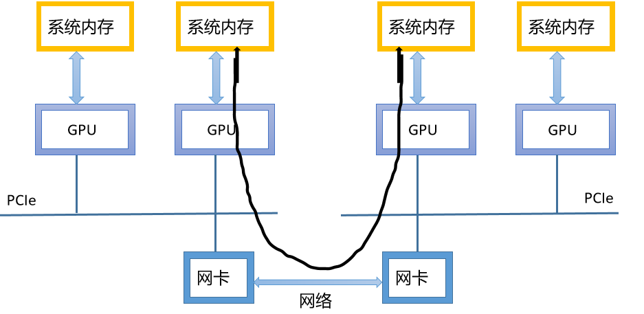
When GPUDirect RDMA is added to CUDA aware MPI, the performance is significantly improved
Note that because CUDA speeds up the calculation and allocation of applications, IO in all applications will quickly become an obstacle to overall performance. GPUDirect provides a straightforward solution by reducing the delay between GPU s.
9.6 summary
Multi GPU system is very suitable for dealing with the problems of large data sets that can not be handled by a single GPU in reality, or the problems of throughput and efficiency that can be solved by using multi GPU system. Typically, there are two configurations for executing multi GPU applications:
Single node multi equipment;
Multi device on multi node GPU acceleration group;
MVAPICH2 is a common implementation form of CUDA aware MPI. It uses InfiniBand, 10GidEiWARP and RoCE network technology to realize the low latency, high bandwidth, scalability and fault tolerance required by high-end computers. The direct transfer of device memory through MPI function greatly simplifies the development of MPI-CUDA program and improves the performance of GPU cluster.
GPUDirect facilitates point-to-point device memory access. The same gpirect can be used on different nodes of the cluster to exchange data directly. The RDMA function of GPUDirect enables third-party devices to directly access GPU global memory, such as solid-state disk, network interface card and Infiniband adapter, which significantly reduces the delay between these devices and GPU.
CUDA provides many ways to manage and execute kernel functions on multiple devices. Applications can be extended across multiple devices within a node or accelerated across GPU cluster nodes. Using calculation to hide the load balance of communication delay can achieve approximately linear performance gain.