Customize one master multi slave serial communication_ one
This is a small record similar to the development log. This article mainly records a communication protocol based on serial communication customized in Bi Shuli. As for why I didn't use modbus, it's just because I didn't use it.
Hardware foundation
In general, there are three main modules for communication in my Bi design: Raspberry pie as the main control board, sensor acquisition board and power drive board. The latter two are boards made by myself with stm32f103rct6. I will show them when I have a chance in the future
In connection, we know that only one serial port of raspberry pie is led out by pin, so I hope to control two stm32 boards at the same time through one serial port, so the idea of a master-slave custom serial communication protocol comes out.
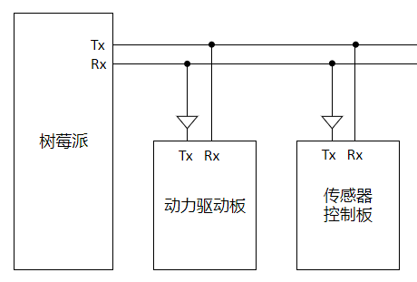
First of all, we need to solve the connection problem: we know that Rx and Tx of the serial ports of two devices need to be connected reversely when connecting, but a small problem needs to be solved when two slaves are connected:
The Tx of two slaves are connected to each other, so that one slave cannot send data when it needs to send data
By checking the data, we know that the serial port of mcu takes the low level as the effective value, so the problem is how to avoid the influence of the high level of Tx of slave 2 when the Tx of slave 1 becomes low.
Obviously, it can be solved by using one diode. I should be clear by going directly to the block diagram:
When slave 1 sends data, Tx low level will pull down host Rx, while slave 2 Tx remains high level without affecting communication.
Agreement idea
My agreement mainly includes the following six contents:
- Start flag: I use the value of '>' directly here
- Target address: there are three modules in total, so there are three addresses
enum ModuleAddrees {
    kRaspberryAddr = 0x1,
    kChuanGanQiAddr = 0x2,
    kQuDongBanAddr = 0x3,
    kReseve1        = 0x4,
    kReseve2        = 0x5,
    kReseve3        = 0x6,
    kReseve4        = 0x7,
};   ///< mark module address
- Message type: used to mark which data type the current packet belongs to. At present, only the following are thought of
enum DataTypeId {
    kAck_dti = 0x0,
    kYaw_dti = 0x1,
    kCio_dti = 0x2,
    kAdc_dti = 0x3,
    kEncoder_dti = 0x4,
    kMoto_dti = 0x5,
    kServe_dti = 0x6,
    kPower_dti = 0x7,

    kReseveLast_dti = 0x1f, //0001 1111
};   ///< tag data type
- Content length: it is the length of the message content simply recorded. It is mainly used for verification. Later, it seems useless. It is too lazy to write verification directly
- Content: it is the main content to carry
- End flag: habitual newline combination "\ r\n", the corresponding array is [13, 10]
Packet encapsulation and de encapsulation
Basically, I can use an array to complete all the above contents. However, in order to reduce one byte, I shifted the values of the target address and message type into an 8-bit data (the upper 3 bits represent the target address and the lower 5 bits represent the message type). I'll go straight to the code. It's so simple and direct
/**
 * @brief Encapsulated packet
 * @param package data packet
 * @param detAddr Target module address
 * @param dti   Data type label
 * @param len   Data length
 * @param srcData Raw data (Group)
 * @return Packet length, construction failed, return - 1
 */
int MES_PackageData(char *package, enum ModuleAddrees detAddr, enum DataTypeId dti,
                    unsigned char len, void *srcData)
{
    int i;
    int result = -1;
    char *p = package;
    unsigned char addrTid = (((unsigned char)detAddr) << 5) | ((unsigned char)dti);

    // Start flag '>'
    *p = '>';
    p++;
    // Module number (3bit) + data type model (5bit)
    *p = addrTid;
    p++;
    // Length of data (Group), unit (byte)
    *p = len;
    p++;
    // Data (Group)
    for (i = 0; i < len; i++, p++) {
        *p = ((char *)srcData)[i];
    }
    // End flag "\ r\n"
    *p = '\r'; p++; *p = '\n';

    // Calculate packet length
    result = p - package + 1;

    return result;
}
/**
 * @brief Disassemble data package
 * @param package data packet
 * @param selfAddr Native module number
 * @param res Obtain data
 * @param dti Data type number
 * @return Data length
 */
int MES_UnpackageData(char *package, enum ModuleAddrees selfAddr,
                    char *res, enum DataTypeId *dti)
{
    int result = -1;
    char *p = package;
    unsigned char temp;
    int i;

    // Judgment start flag
    if (*p != '>') {
        return result;
    }
    p++;
    // Judging module number (3bit) + obtaining data type model (5bit)
    temp = *p;
    if ((temp >> 5) != (unsigned char)selfAddr) {
        return result;
    }
    *dti = temp & 0x1f;
    p++;
    // get data
    result = *p;
    p++;
    for (i = 0; i < result; i++, p++) {
        res[i] = *p;
    }

    return result;
}
The above is the code of stm32 slave, and the following is the python code written on raspberry pie
def __packData(self, detAddr = ModuleAddrees.kNone,
                   dti = DataTypeId.kAdc_dti,
                   len = 0, srcData = np.zeros(0,dtype = np.uint8)):
        '''
        :breif Package data
        :param detAddr:  Destination address
        :param dti:   data type
        :param len: Parameter length
        :param srcData: parameter list
        :return: Complete packet np.ndarray
        '''
        pack = np.zeros(len + 5, dtype=np.uint8)
        pack[0] = ord('>') # begin flag
        pack[1] = np.uint8(detAddr << 5) | np.uint8(dti & 0x1f)
        pack[2] = np.uint8(len)
        pack[-2] = ord('\r')
        pack[-1] = ord('\n')

        i = 0
        while i < len:
            pack[i+3] = np.uint8(srcData[i])
            i += 1

        return pack

def __Unpackage(self, pack = '', len = 0):
        '''
        Unpack data packet
        :param pack:
        :param len:
        :return: Content length type
        '''
        pck = np.array(list(pack), dtype=np.uint8)
        if pack.__len__() < 6:
            dataContent = []
            dataType = -1
            dataSize = -1
            return (dataContent, dataSize, dataType)

        dataContent = pck[3:-2]
        dataSize = pck[2]
        dataType = DataTypeId(pck[1] & 0x1f)

        return (dataContent, dataSize, dataType)

'''
These two functions are a class method and cannot be used directly. Just see the process.

At this point, the content of my agreement is basically over. Later, I mainly record the work and precautions to be done when using the raspberry pie serial port for the first time
'''
Notes on the use of raspberry pie python serial port
Change the serial device driver of raspberry pie
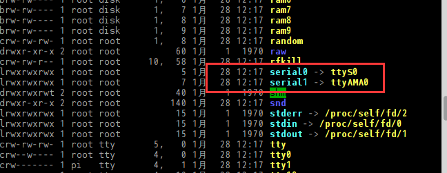
I use raspberry pie 4b. There are two serial ports inside the chip: one is called hardware serial port (/ dev/ttyAMA0) and the other is called mini serial port (/ dev/ttyS0). The two differences are that ttyAMA0 is a peripheral serial port with a separate clock, while ttyS0 is a simple serial port. The clock is provided by the kernel, so AMA0 will be relatively stable, and ttyS0 will be affected by the kernel clock.
Through the instruction ls -l /dev, it can be seen that the serial port led out by the current pin is ttyS0, so the first step is to modify the mapping relationship
Reference blog: Modify serial port device mapping of raspberry pie
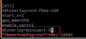
The main content is to find the relevant files. Here I am "/ boot/overlays/miniuart-bt.dtbo". The systems of different versions will be somewhat different

Then edit / boot / config txt
Add a line of code dtoverlay = "corresponding file name" to the file
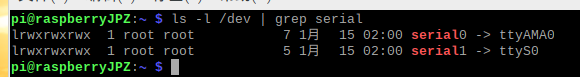
Then save the file and restart the raspberry pie to make it effective.
View the equipment here and the corresponding relationship will be changed
Turn off console functions
At first, in order to enter the system through the serial port, the console function was turned on. It needs to be turned off here. Two commands can be used
sudo systemctl stop serial-getty@ttyAMA0.service
sudo systemctl disable serial-getty@ttyAMA0.service
Every blog I read mentioned that / boot / CmdLine. Needs to be modified txt
Delete all the contents about the serial port, but I find that there is no more in me, so I need to transpose the hyperlinks above
Restart again and you can use it normally
Use of python serial port
Instead of using the WiringPi library, I directly used PySerial. In the process of learning and using, I found that the parsing of python serial port data is not as convenient as that of C language (it should be too easy for me). I am always struggling with how python declares the data and how to forcibly convert the data.
So far, I have found it relatively convenient to send array types through the serial port, so in python, my serial port packets are passed in the form of arrays (dtype=np.uint8).
Maybe it's because of the concept that everything is an object in python that I can't implement data structures with the same memory and different data types like union in C language (I'm too good)
So I'm going to write a static library in c language later, and python calls the library to realize such a function, hoping to ensure the accuracy of the data
Communication response test
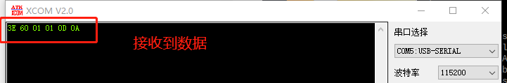
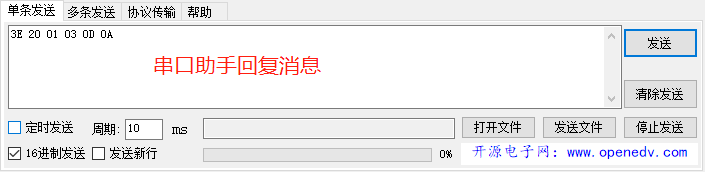
In order to facilitate the response of analog messages, I plug the slave directly into the serial port assistant, so that I can control the slave to send.
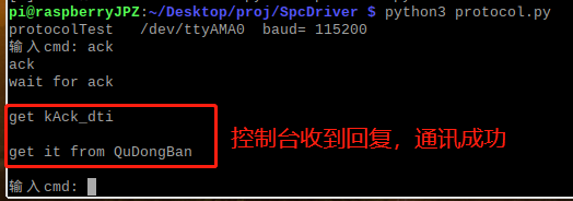
The test idea is as follows: Raspberry pie sends a response command package to the slave to reply. If raspberry pie can send and receive normally, a message will be displayed on the console. If it is normal, it is successful
- Write test demo
def __task_enter(self,argm = []):
'''
Analyze and respond to the received data
:return:
'''
lock = threading.Lock()
try:
while self.__TaskIsRun:
# step.1 receive packet
(self.r_data, self.r_len) = self.ReadLine()
# step.2 parsing packets
lock.acquire()
(cont, size, type) = self.__Unpackage(self.r_data, self.r_len)
lock.release()
# step.3 analysis data
if type == DataTypeId.kAck_dti: #Analyze the reply content
print("get kAck_dti\n")
if cont[0] == ModuleAddrees.kChuanGanQiAddr.value:
self.dataApi.ack_CGQ = 1
self.ipc.cmdAckCGQ.set()
elif cont[0] == ModuleAddrees.kQuDongBanAddr.value:
self.dataApi.ack_QDB = 1
self.ipc.cmdAckQDB.set()
else:
print("ack pack cont error\n")
pass
elif type == DataTypeId.kMoto_dti:
print("get kMoto_dti\n")
pass
continue
except:
print("The thread is end >> " + self.task.getName())
return
if __name__ == "__main__":
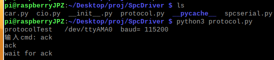
prl = SpcProtocol("protocolTest", "/dev/ttyAMA0", 115200)
prl.StartTask()
while True:
key = input("input cmd: ")
print(key, end = '\n')
if key == 'ack':
prl.SendCmdAck(ModuleAddrees.kQuDongBanAddr) # Send reply command
print("wait for ack\n")
prl.ipc.cmdAckQDB.wait()
print('get it from QuDongBan\n')
continue
-
Input command send and check
-
View console replies
In addition, other wrong data reply packets are also tested, and the error console in the setting will also respond accordingly.
So far, the user-defined communication protocol has preliminarily completed the point-to-point experiment, and the communication response to two slaves will be tested tomorrow.