MPU6050 is a commonly used attitude sensor. There are three-axis accelerometer and three-axis gyroscope six axis sensor modules in MPU6050, and DMP can be used to directly output the data after attitude calculation. Through IIC communication, the data after attitude settlement can be output. However, it is found that DMP is rarely used for attitude calculation in most flight control systems, because DMP is used for attitude calculation The state solution will drift, and the convergence speed is slow. This module has its own temperature sensor. This temperature sensor does not measure the temperature of the surrounding environment of the body, but is like the CPU temperature often seen in the computer housekeeper. It measures the temperature of MPU6050 at this time, so what's the use of this temperature? When the MPU6050 has its own temperature, it has an impact on the data. At this time, there will be something called temperature drift. Then we usually use compensation method to make the data closer to the real value through compensation.
For the initialization of MPU6050, we need to set the sensitivity of gyroscope and accelerometer according to our own needs. The following figure shows MPU6050: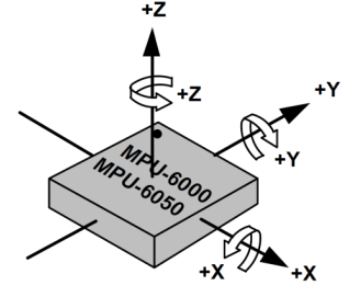
It can be seen that the MPU6050 has three axes X, Y and Z. the attitude calculated from these three axes is the roll corresponding to Y, The X-axis corresponds to pitch, the z-axis corresponds to heading. For MPU6050 initialization, the code will not be pasted. However, when the gyroscope and acceleration are not calibrated, the data is biased or the fluctuation range is large. In this case, the gyroscope and accelerometer need to be calibrated. For example, if the accelerometer and gyroscope are calibrated, the static calibration is generally OK. If you want to If you want to calibrate more accurately, you can also use the six face calibration. Friends who have played pixhawk know that when you calibrate the accelerometer, it is the six face calibration. In general, the static calibration can also meet our needs. The calibration process: for example, collect 50 data, add them, and then calculate the mean value. Then you can get an accelerometer and a gyroscope Offset, then the corrected data can be obtained by subtracting the offset from the collected three-axis data each time, with few words about the code:
//Accelerometer calibration
if(ACC_Offset == 1&&ACC_Offset_ok)
{
   /* Counting and accumulation */
   acc_sum_cnt++;
   sum_temp[A_X] += g_MPUManager.Acc_initX;
   sum_temp[A_Y] += g_MPUManager.Acc_initY;
   sum_temp[A_Z] += g_MPUManager.Acc_initZ - 4096;
   sum_temp[TEM] += g_MPUManager.Tempreature;
    /* Judge whether the count meets the conditions */
    if( acc_sum_cnt >= OFFSET_AV_NUM )
    {
       /* Calculate verification data */
       g_MPUManager.Acc_Offset.x = sum_temp[A_X]/OFFSET_AV_NUM;
       g_MPUManager.Acc_Offset.y = sum_temp[A_Y]/OFFSET_AV_NUM;
       g_MPUManager.Acc_Offset.z = sum_temp[A_Z]/OFFSET_AV_NUM;
       g_MPUManager.Acc_Temprea_Offset = sum_temp[TEM]/OFFSET_AV_NUM;
       /* Clear process variable */
       acc_sum_cnt =0;
       ACC_Offset_ok = 0;
    }
}
/* Gyroscope calibration */
if(Gyro_Offest == 1 && Gyro_Offest_ok)
{
   /* Counting and accumulation */
   gyro_sum_cnt++;
   sum_temp[G_X] += g_MPUManager.Gyro_initX;
   sum_temp[G_Y] += g_MPUManager.Gyro_initY;
   sum_temp[G_Z] += g_MPUManager.Gyro_initZ;
   sum_temp[TEM] += g_MPUManager.Tempreature;
   /* Judge whether the count meets the conditions */
   if( gyro_sum_cnt >= OFFSET_AV_NUM )
   {
      /* Calculate verification data */
      g_MPUManager.Gyro_Offset.x = (float)sum_temp[G_X]/OFFSET_AV_NUM;
      g_MPUManager.Gyro_Offset.y = (float)sum_temp[G_Y]/OFFSET_AV_NUM;
      g_MPUManager.Gyro_Offset.z = (float)sum_temp[G_Z]/OFFSET_AV_NUM;
      g_MPUManager.Gyro_Temprea_Offset = sum_temp[TEM]/OFFSET_AV_NUM;
      /* Clear process variable */
      gyro_sum_cnt =0;
      Gyro_Offest_ok = 0;
   }
}
The above is the static calibration process, so the output waveform of the accelerometer and gyroscope is relatively stable when the body is stationary, but the body can observe some fluctuations in the movement of the data, because the accelerometer is more sensitive to the body's attitude, because the rotation of the motor produces high-frequency noise, and the gyroscope is integrated So there will be a big integration error, which can't be eliminated. So we usually use a low-pass filter to filter out the high-frequency noise. How can we see it through the waveform? If we observe that there is a spike noise in the waveform, then we can use low-pass filter or sliding mean filter to filter out the spike. Before, we did a low-pass filter and sliding mean filter The results of the two filtering algorithms are compared, but the effect picture of low-pass filtering seems to have been deleted by me, and only the effect picture of moving average filtering is left. Let's see:
This is the original data of the accelerometer. Look at whether the fluctuation is large.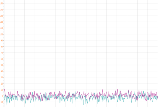
After the moving average filtering algorithm, the accelerometer data is very stable!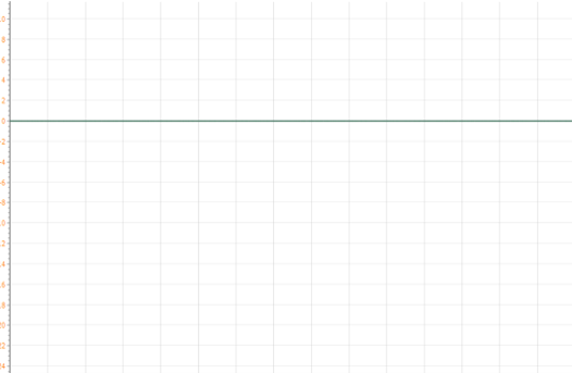
I will not release the screenshot of the gyroscope data. The effect is actually the same as that of the accelerometer.
What is moving average filtering? It refers to the establishment of a data buffer to store n sampling data in order. Each time a new data is sampled, the earliest sampled data will be discarded, and then the arithmetic average or weighted average of N data will be calculated. Each time a sample is taken, a new average value can be calculated, thus forming a kind of circular queue structure mode. Because the gyroscope and acceleration data are easy to be vibrated by the rotation of the motor, there is noise data in the data, which makes the data fluctuate greatly, and it is suitable for the system with high frequency oscillation. After adding the filtering algorithm, the periodic interference is good Good restraining effect makes acceleration data and gyroscope data smoother, but it still has its disadvantages, low sensitivity, poor restraining effect on occasional impulse infection, and serious situation without impulse interference. However, compared with MPU6050's internal low-pass filter, it is much better to use MPU6050's internal low-pass filter first Wave first processes the output data, and then uses the moving average filter to process the output data. The dry goods are coming. For those with better logic, you can write your own code, or you can refer to mine.
#define FILTER_NUM  8 // //Number of sliding average filtering values
/* Update filter sliding window temporary array */
FILT_BUF[A_X][filter_cnt] = mpu6050_tmp[A_X];//Store acceleration data
FILT_BUF[A_Y][filter_cnt] = mpu6050_tmp[A_Y];
FILT_BUF[A_Z][filter_cnt] = mpu6050_tmp[A_Z];
FILT_BUF[G_X][filter_cnt] = mpu6050_tmp[G_X];//Store gyroscope data
FILT_BUF[G_Y][filter_cnt] = mpu6050_tmp[G_Y];
FILT_BUF[G_Z][filter_cnt] = mpu6050_tmp[G_Z];
/* Update filter slide window array */
for(i=0; i<FILTER_NUM; i++)
{
	FILT_TMP[A_X] +=FILT_BUF[A_X][i];
	FILT_TMP[A_Y] += FILT_BUF[A_Y][i];
	FILT_TMP[A_Z] += FILT_BUF[A_Z][i];
	FILT_TMP[G_X] += FILT_BUF[G_X][i];
	FILT_TMP[G_Y] += FILT_BUF[G_Y][i];
	FILT_TMP[G_Z] += FILT_BUF[G_Z][i];
}
/* Get the processed accelerometer data */
MPUManager.Acc.x=(float)(FILT_TMP[ACC_X] )/(float)FILTER_NUM;
MPUManager.Acc.y=(float)( FILT_TMP[ACC_Y])/(float)FILTER_NUM;
MPUManager.Acc.z=(float)(FILT_TMP[ACC_Z] )/(float)FILTER_NUM;
/* Get the processed gyroscope data */
MPUManager.Gyro.x=(float)(FILT_TMP[GROY_X] )/(float)FILTER_NUM;
MPUManager.Gyro.y=(float)(FILT_TMP[GROY_Y] )/(float)FILTER_NUM;
MPUManager.Gyro.z=(float)(FILT_TMP[GROY_Z] )/(float)FILTER_NUM;