abstract
DBC is the abbreviation of DataBase CAN and represents the database file of can. In this file, the relevant information of CAN communication is defined in detail, such as message name, message ID, signal name, signal layout, etc. The communication of can network is based on the description of this document. Although other communication methods, such as Ethernet, are also used for on-board communication, at present, the role of DBC is still very powerful.
The DBC file is generated according to the format described in the DBC File Format Documentation file of Vector company. The following is a description of some symbols in DBC.
1. DBC template
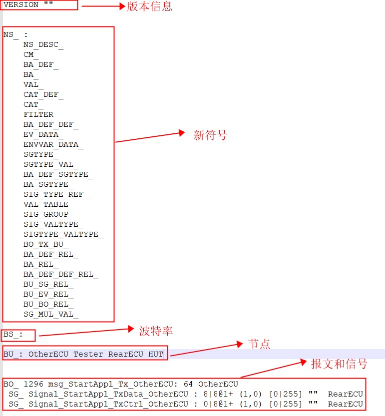
The following figure shows a DBC template style. Some information after opening in text format is as follows:


2. General description
2.1 keywords
| keyword | object type |
|---|---|
| BU_ | network node |
| BO_ | message |
| SG_ | signal |
| EV_ | environment variable |
It may not be clear how to use the keywords in the table, but please don't worry. Please continue to read.
2.2 data type
Similar to C language, attribute values in DBC files are also distinguished by data types. The following table shows the data types that can be selected in Chinese DBC files.
| Symbol | type |
|---|---|
| unsigned_interger | unsigned int |
| singed_integer | signed int |
| double | Double precision floating point number |
| char_string | character string |
| C_identifier | C language variable name |
If you don't understand the first four types in the table, please use the data types in Baidu C language by yourself. There is no explanation here, just C_indentifier. C_identifiers must start with alphabetic characters or underscores and can consist of alphabetic, numeric characters and underscores. For example: Abc_string, acb_123_string
2.3 syntax description
The extended BNF notation is used in the DBC file for syntax description.
BNF refers to Backus Naur format, which is a symbolic rule describing the syntax of computer language. Please refer to Baidu Encyclopedia for detailed explanation. Click here directly!
| Symbol | meaning |
| = | =The name on the left is defined by the syntax on the right, which is simply assignment |
| ; | End a definition with a semicolon |
| | | Vertical bars represent alternatives |
| [ ... ] | Definitions in inverse brackets are optional (0 or once) |
| { ... } | Definitions in braces can be repeated (0 or more times) |
| ( ... ) | Parentheses are used to define grouping elements |
| ' ... ' | Text in hyphens must be displayed as defined |
| (* ... *) | Indicates a comment |
3. Overall format of DBC
The format of the entire DBC file is:
DBC_file =
	version
	new_sysmbols
	bit_timing                                {*Abandoned but still needed*}
	nodes
	value_tables
	messages
	message_transmitters
	environment_variables
	environment_variables_data
	signal_types
	comments
	attribute_definitions
	sigtype_attr_list
	attribute_defaults
	value_descriptions
	category_definitions                      {*obsolete *}
	categories                                {*obsolete *}
	filter                                    {*obsolete *}
	signal_type_refs
	signal_groups
	signal_extended_value_type_list;
3.1 mandatory and non mandatory parts
| Necessary part | explain | Non essential part | explain |
|---|---|---|---|
| bit_timing | This section is required but is usually empty | signal_types | General DBC does not use this part, and this article does not describe the relevant usage |
| nodes | This section is required to define network nodes | sigtype_attr_list | |
| messages | This section defines messages and signals | category_definitions | |
| — | — | categories | |
| — | — | filter | |
| — | — | signal_type_refs | |
| — | — | signal_extended_value_type_list |
3.2 format of symbol definition
The header of the DBC file contains version information and new symbol entries
3.2.1 format of version
version = ['VERSION' ' " ' { CANdb_version_string } ' " ' ];
Example 1: VERSION ""
Example 2: version "v1.0"
The contents in double quotation marks can be empty or user-defined.
3.2.2 new_ Format of symbols
new_symbols = [ '_NS' ':' ['CM_'] ['BA_DEF_'] ['BA_'] ['VAL_']
['CAT_DEF_'] ['CAT_'] ['FILTER'] ['BA_DEF_DEF_'] ['EV_DATA_']
['ENVVAR_DATA_'] ['SGTYPE_'] ['SGTYPE_VAL_'] ['BA_DEF_SGTYPE_']
['BA_SGTYPE_'] ['SIG_TYPE_REF_'] ['VAL_TABLE_'] ['SIG_GROUP_']
['SIG_VALTYPE_'] ['SIGTYPE_VALTYPE_'] ['BO_TX_BU_']
['BA_DEF_REL_'] ['BA_REL_'] ['BA_DEF_DEF_REL_'] ['BU_SG_REL_']
['BU_EV_REL_'] ['BU_BO_REL_'] ];
Bloggers always think "first"_ NS' seems not quite right, but the official document of Vector is written like that. Let's ignore it here for the time being.
3.2.3 bit timing format
The bit timing section defines the baud rate and BTR register value of the network. This section is obsolete, but the keyword "BS_" Must appear in the DBC file.
bit_timing = 'BS_:' [ baudrate ' : ' BTR1 ' , ' BTR2 ] ;
baudrate = unsigned_integer ;
BTR1 = unsigned_integer ;
BTR2 = unsigned_integer ;
At present, it is usually written in the following form. Baud rate and BTR are no longer used
Example: BS_:
3.2.4 format of nodes
The node defines all nodes participating in communication in this network. The node definition must be unique, and the naming method is the same as that of C language.
nodes = 'BU_:' {node_name} ;
node_name = C_identifier ;
Example: bu_: ECU1 ECU2 ECU3 Tester
Define nodes ECU1, ECU2, ECU3, and Tester
3.2.5 format of messages [core]
The message part defines the names and attributes of all frames in the cluster and the signals transmitted on the frames
messages = {message} ;
message = BO_ message_id message_name ':' message_size transmitter {signal} ;
message_id = unsigned_integer ;
Where message_id must be unique in this network. CAN ID CAN be standard frame ID or extended frame ID. their difference lies in the length of frame ID. the length of frame ID of standard frame is 11 bits, that is, the range of frame ID is 000-7FF. The frame ID length of the extended frame is 29 bits, that is, the range of frame ID is 0000-1fff ffff. Please refer to relevant CAN protocol specifications for specific information.
message_name = C_identifier ;
message_ The naming rules of name are the same as those of C language.
message_size = unsigned_integer ;
message_size, the so-called DLC, is an unsigned integer number in Byte, which specifies the number of bytes in the message data field. Standard CAN supports up to 8 bytes and canfd supports up to 64 bytes
transmitter = node_name | 'Vector__XXX' ;
transmitter refers to the node that sends the message. The node must be a node defined in the nodes section or a 'vector'__ XXX’.
‘Vector__XXX 'means that if a message does not specify a sending node, it must be set to' vector '_ XXX’.
Example: BO_ 100 test_message1: 8 ECU1
Define message test_message1, CAN ID 100 (dec), DLC 8, sender ECU1
Example: BO_ 101 test_message2: 8 ECU2
Define message test_message2, CAN ID 101 (dec), DLC 8, sender ECU2
Example: BO_ 103 test_message3: 8 ECU3
Define message test_message3, CAN ID 102 (dec), DLC 8, sender ECU3
3.2.6 format of signals [core part]
The signal part of the message lists all signals placed on the message, as well as the position and attribute of the signal in the data field of the message.
signal = 'SG_' signal_name multiplexer_indicator ' : ' start_bit ' | ' signal_size ' @ ' byte_order value_type ' ( ' factor ' , ' offset ' ) ' ' \[ ' minimum ' | ' maximum ' \] ' unit receiver {',' receiver} ;
signal_name = C_identifier ;
The multiplexer indicator indicates whether the signal is a normal signal, a multiplexed signal switch or a multiplexed signal.
The "M" (uppercase) character defines the signal as a multiplexer switch. Only one signal in a single message can be a multiplexer switch.
The "m" (lowercase) character followed by an unsigned integer defines the signal as multiplexed.
If the switch value of the multiplexer signal is equal to its multiplexer_switch_value, the multiplexed signal is transmitted in the message.
multiplexer_indicator = ' ' | 'M' | m multiplexer_switch_value ;
This item can be omitted. At present, the blogger has not encountered a DBC using this parameter. Interested students can study it by themselves.
start_bit = unsigned_integer ;
signal_size = unsigned_integer ;
start_bit specifies the starting bit of the signal in the data segment of the frame, which must be within the range of (8*message_size-1). signal_size is the length of the signal.
byte_order = '0' | '1' ;
0 refers to intel format, which is called small end mode; 1 stands for motorola format, which is called big end mode. Please refer to the following articles for details. This article will not elaborate too much.
value_type = '+' | '-' ;
+Represents an unsigned number, - represents a signed number
Factor and offset are used to convert the original value to the physical value. Minimum and maximum represent the maximum and minimum values of the signal. These four parameters are of double type
The relationship between factor and offset in calculation is as follows:
physical_value = raw_value * factor + offset
raw_value = (physical_value – offset) / factor
Tips: the so-called physical value is what we expect to use. The original value is the value carried in the message data segment.
Unit is a string used to represent the signal unit. If there is no unit, this item is empty
receiver = node_name | 'Vector__XXX' ;
The receiver is the same as the transmitter mentioned earlier. I won't repeat it here.
Example 1:
BO_ 100 test_message1: 8 ECU1
SG_ test_signal1: 8|2@1+ (1,0) [0|3] "" ECU2,ECU3
Define test_ A signal test in message1_ Signal1, the starting bit is 8, the length is 2, adopts motorola format, unsigned integer, the factor is 1, the offset is 0, the minimum and maximum values are 0 and 3, and there is no unit, so there is no content in the double quotation marks, and the receivers are ECU2 and ECU3.
Example 2:
BO_ 101 test_message2: 8 ECU2
SG_ test_signal2: 10|5@1+ (1,-1) [0|31] "cm" ECU3
Define test_ A signal test in message2_ Signal2, the starting bit is 10, the length is 5, adopts motorola format, unsigned integer, the factor is 1, the offset is - 1, the minimum and maximum values are 0 and 31, the unit is cm, and the receiver is ECU3.
Example 3:
BO_ 102 test_message2: 8 ECU3
SG_ test_signal3: 3|16@0+ (1,0) [0|65535] "" ECU1,ECU2
Define test_ A signal test in message3_ Signal3, the starting bit is 3, the length is 16, adopts intel format, unsigned integer, factor is 1, offset is 0, minimum and maximum values are 0 and 65535, there is no unit, so there is no content in double quotation marks, and the receivers are ECU1 and ECU2.
3.2.7 format of value encodings
The signal value description defines the encoding of the original value of a specific signal.
value_descriptions = { value_descriptions_for_signal | value_descriptions_for_env_var } ;
value_descriptions_for_signal = 'VAL_' message_id signal_name { value_description } ';' ;
Example: VAL_ 100 test_signal1 0 “Off” 1 “On” 2 “Reserved” 3 “Invalid” ;
Define test in message with message ID 100_ For the encodings of signal1, 0 means off, 1 means on, 2 means reserved, and 3 means invalid value.
In fact, the encoding value is to tell the diagnosis and tester what the relative value means.
This attribute is not required for every signal.
3.2.8 format of environment variable
In the environment variables section, the environment variables used in system simulation and bus simulation tools.
This property is usually used in bus emulation.
environment_variables = {environment_variable}
environment_variable = 'EV_' env_var_name ':' env_var_type '[' minimum '|' maximum ']' unit initial_value ev_id access_type access_node {',' access_node } ';' ;
env_var_name = C_identifier ;
env_var_type = '0' | '1' | '2' ; (* 0=integer, 1=float, 2=string *)
minimum = double ;
maximum = double ;
initial_value = double ;
ev_id = unsigned_integer ; (* obsolete *)
access_type = 'DUMMY_NODE_VECTOR0' | 'DUMMY_NODE_VECTOR1' |  'DUMMY_NODE_VECTOR2' | 'DUMMY_NODE_VECTOR3' ; (* 0=unrestricted, 1=read, 2=write, 3=readWrite *)
access_node = node_name | 'VECTOR_XXX' ;
Like value encodings, environment variables can also have this definition
value_descriptions_for_env_var = 'VAL_' env_var_aname
{ value_description } ';' ;
This paper does not discuss the properties related to bus simulation. Students interested in this part, please consult the relevant materials by yourself.
3.2.9 format of signal group
A signal group is used to define a group of signals in a message. The concept of signal group belongs to the part of functional safety end-to-end protection (E2E), one of which is that the signals of a group must be updated together.
signal_groups = 'SIG_GROUP_' message_id signal_group_name repetitions ':' { signal_name } ';' ;
signal_group_name = C_identifier ;
repetitions = unsigned_integer ;
Example: SIG_GROUP_ 100 test_message1_group 1 : CheckSum_test_message1 test_signal1 RollingCounter_test_message1 ;
Define the signal group test in the message with CAN ID 100_ message1_ Group, repetitions is 1, and the signal includes CheckSum_test_message1,test_signal1,RollingCounter_test_message1.
Tips: careful students may have noticed that there is a semicolon after the definition, which means'; 'in the format definition, This indicates that a semicolon is required at the end of the statement. Although we use tools to modify DBC now, bloggers mention it here.
Briefly describe CheckSum and RollingCounter. CheckSum is the CheckSum, which will verify the signals in the group before sending the message, and then store the verification results in this signal. RollingCounter is a counter, which is mainly used to prevent data errors in case of frame loss. E2E will also be checked at the receiving end of the signal, and the two signals will be checked according to the algorithm. A detailed description is beyond the scope of this article.
3.2.10 format of comment
The annotation section contains object annotations. It mainly describes the description of the signal.
comments = {comment} ;
comment = 'CM_' (char_string |  'BU_' node_name char_string |  'BO_' message_id char_string |  'SG_' message_id signal_name char_string |  'EV_' env_var_name char_string)  ';' ;
Example: CM_ SG_ 100 test_signal1 “The left door status” ;
Define the signal test in frame 100_ The description of signal1 is "The left door status"
Example: CM_ “CAN communication matrix for power train electronics” ;
If so, the Comment will appear in the Comment of the Network
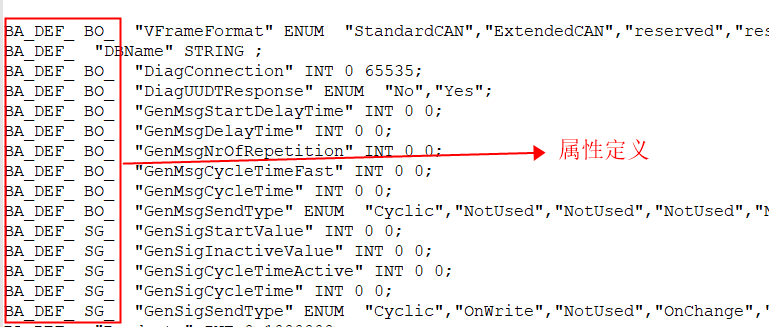
3.2.11 format of user defined attribute
In DBC, in addition to the specified attributes, you can also have user-defined attributes, but you also need to abide by certain rules.
User defined attributes must define these additional attributes using attribute definitions with attribute defaults. For each object that has a value defined for an attribute, an attribute value entry must be defined. If no property value entry is defined for an object, the property value of the object is the default value of the property.
Attributes are defined as follows:
attribute_definitions = { attribute_definition } ;
attribute_definition = 'BA_DEF_' object_type attribute_name attribute_value_type ';' ;
object_type = '' | 'BU_' | 'BO_' | 'SG_' | 'EV_' ;
attribute_name = '"' C_identifier '"' ;
attribute_value_type = 'INT' signed_integer signed_integer |
'HEX' signed_integer signed_integer |
'FLOAT' double double |
'STRING' |
'ENUM' [char_string {',' char_string}]
attribute_defaults = { attribute_default } ;
attribute_default = 'BA_DEF_DEF_' attribute_name attribute_value
';' ;
attribute_value = unsigned_integer | signed_integer | double |
char_string ;
Definition method of attribute value:
attribute_values = { attribute_value_for_object } ;
attribute_value_for_object = 'BA_' attribute_name (attribute_value |
'BU_' node_name attribute_value |
'BO_' message_id attribute_value |
'SG_' message_id signal_name attribute_value |
'EV_' env_var_name attribute_value)
';' ;
For example, chestnuts:
Define an attribute that all messages have
BA_DEF_ BO_ "GenMsgSendType" ENUM "Cyclic","Event" ;
Because the sending type is for messages, all use BO_, If it is for the signal, use SG_, GenMsgSendType is the defined attribute name, ENUM refers to the enumeration type, which contains two types: "cycle" and "Event"
4 overall Preview
Basically, examples are given for each attribute, but they are scattered. Let's put the whole together. Let's take a look at the overall structure
VERSION " "
NS_:
	NS_DESC_
    CM_
   	BA_DEF_
    BA_
    VAL_
    CAT_DEF_
   	CAT_
    FILTER
    BA_DEF_DEF_
    EV_DATA_
	ENVVAR_DATA_
	SGTYPE_
	SGTYPE_VAL_
	BA_DEF_SGTYPE_
	BA_SGTYPE_
	SIG_TYPE_REF_
	VAL_TABLE_
	SIG_GROUP_
	SIG_VALTYPE_
	SIGTYPE_VALTYPE_
	BO_TX_BU_
	BA_DEF_REL_
	BA_REL_
	BA_DEF_DEF_REL_
	BU_SG_REL_
	BU_EV_REL_
	BU_BO_REL_
BS_ :
BU_ :  ECU1 ECU2 ECU3 Tester

BO_ 100 test_message1: 8 ECU1
	SG_ CheckSum_test_message1 : 7|8@0+ (1,0) [0|255] ""  ECU2,ECU3
	SG_  test_signal1: 8|2@1+ (1,0) [0|3] ""  ECU2,ECU3
	SG_ RollingCounter_test_message1: 63|4@0+ (1,0) [0|15] ""  ECU2,ECU3
BO_ 101 test_message2: 8 ECU2
    SG_  test_signal2: 10|5@1+ (1,-1) [0|31] "cm"  ECU3
BO_ 103 test_message3: 8 ECU3
    SG_  test_signal3: 3|16@0+ (1,0) [0|65535] ""  ECU1,ECU2

CM_ SG_ 100  test_signal1 "The left door status" ;
CM_ "CAN communication matrix for power train electronics" ;

BA_DEF_ BO_  "GenMsgSendType" ENUM  "Cyclic","Event";

VAL_ 100 test_signal1 0 "Off" 1 "On" 2 "Reserved" 3 "Invalid";

SIG_GROUP_ 100 test_message1_group 1 : CheckSum_test_message1 test_signal1 RollingCounter_test_message1 ;
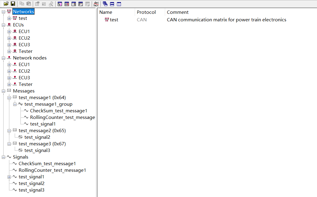
Copy the above contents into the text and modify the file suffix to DBC, blogger here named test dbc. After opening, see the following figure:

Tips: note that keyword and attribute definitions are in order. The order followed is new in the file header_ Sequence of symbols; Another is that there must be a semicolon after the attribute definition entry, otherwise an error will be reported. If there are students who modify DBC text manually, remember!!!