How to use generalized inverse kinematics to plan the joint space trajectory of a manipulator?
Combining multiple constraints, a trajectory is generated to guide the gripper to the cup placed on the table. These constraints ensure that the gripper approaches the cup in a straight line and that the gripper is kept at a safe distance from the table without determining the posture of the gripper in advance.
Set up robot model
The model of KUKA LBR iiwa(7-DOF robot manipulator) is used. The importrobot generates the rigidBodyTree model from the description stored in the URDF (Unified Robot description Format) file.
lbr = importrobot('iiwa14.urdf'); % 14 kg payload version
lbr.DataFormat = 'row';
gripper = 'iiwa_link_ee_kuka';
Define the size of the cup:
cupHeight = 0.2;
cupRadius = 0.05;
cupPosition = [-0.5, 0.5, cupHeight/2];
Add a fixed object to the robot model to represent the center of the cup
body = rigidBody('cupFrame');
setFixedTransform(body.Joint, trvec2tform(cupPosition))
addBody(lbr, body, lbr.BaseName);
Describe planning issues:
The goal is to generate a series of robot configurations that meet the following conditions:
(1) Start in master configuration
(2) There is no mutation in robot configuration
(3) Keep the gripper at least 5cm (z = 0) from the "table"
(4) When the cup is close, the claws should be aligned with the cup
(5) Use the gripper to finish 5 cm from the center of the cup
Constraint objects are used to generate robot configurations that meet these conditions.
The generated trajectory is composed of five configuration path markers.
The first path point q0 is set to the home configuration. Use repmat to pre allocate the remaining configurations in qwaypoint.
numWaypoints = 5;
q0 = homeConfiguration(lbr);
qWaypoints = repmat(q0, numWaypoints, 1);
Create a generalizedingverse Kinematics solver that accepts the following constraint inputs:
(1) Cartesian limit - limits the height of the gripper
(2) Position target - specifies the position of the cup relative to the holder
(3) Target constraint - align the retainer with the cup shaft
(4) Locate the target - maintain the fixed direction of the gripper when approaching the cup
(5) Joint position boundary - limits the change in joint position between waypoints
gik = generalizedInverseKinematics('RigidBodyTree', lbr, ...
    'ConstraintInputs', {'cartesian','position','aiming','orientation','joint'})
gik =
generalizedInverseKinematics with properties:
NumConstraints: 5
ConstraintInputs: {1x5 cell}
RigidBodyTree: [1x1 rigidBodyTree]
SolverAlgorithm: 'BFGSGradientProjection'
SolverParameters: [1x1 struct]
Create constraint objects
Creates a constraint object that is passed as input to the solver. These objects contain the parameters required for each constraint. Modify these parameters as needed between calls to the solver.
Create a Cartesian boundary constraint that requires the gripper to be at least 5 cm above the table (negative z direction).
All other values are assigned inf or - inf
heightAboveTable = constraintCartesianBounds(gripper);
heightAboveTable.Bounds = [-inf, inf; ...
                           -inf, inf; ...
                           0.05, inf]
heightAboveTable =
constraintCartesianBounds with properties:
EndEffector: 'iiwa_link_ee_kuka'
ReferenceBody: ''
TargetTransform: [4x4 double]
Bounds: [3x2 double]
Weights: [1 1 1]
Create a constraint on the position of the cup relative to the retainer with a tolerance of 5 mm.
distanceFromCup = constraintPositionTarget('cupFrame');
distanceFromCup.ReferenceBody = gripper;
distanceFromCup.PositionTolerance = 0.005
distanceFromCup =
constraintPositionTarget with properties:
EndEffector: 'cupFrame'
ReferenceBody: 'iiwa_link_ee_kuka'
TargetPosition: [0 0 0]
PositionTolerance: 0.0050
Weights: 1
By placing the target above the robot, an aiming constraint is created, requiring iiwa_ link_ The z-axis of the EE frame is approximately vertical. iiwa_ link_ The EE frame is oriented so that the retainer is aligned with the cup axis.
alignWithCup = constraintAiming('iiwa_link_ee');
alignWithCup.TargetPoint = [0, 0, 100]
alignWithCup =
constraintAiming with properties:
EndEffector: 'iiwa_link_ee'
ReferenceBody: ''
TargetPoint: [0 0 100]
AngularTolerance: 0
Weights: 1
Create joint position boundary constraints. Set the Bounds attribute of this constraint according to the previous configuration to limit changes in joint position.
limitJointChange = constraintJointBounds(lbr)
limitJointChange =
  constraintJointBounds with properties:

     Bounds: [7x2 double]
    Weights: [1 1 1 1 1 1 1]
Create an orientation constraint for the gripper with a tolerance of one degree. This constraint requires the orientation of the gripper to match the value specified by the TargetOrientation property. Use this constraint to fix the direction of the fixture in the final approach to the cup.
fixOrientation = constraintOrientationTarget(gripper);
fixOrientation.OrientationTolerance = deg2rad(1)
fixOrientation =
  constraintOrientationTarget with properties:

             EndEffector: 'iiwa_link_ee_kuka'
           ReferenceBody: ''
       TargetOrientation: [1 0 0 0]
    OrientationTolerance: 0.0175
                 Weights: 1
Find a configuration pointing to the cup
This configuration should place the retainer at a distance from the cup so that the final access can be correctly aligned with the retainer.
intermediateDistance = 0.3;
Constraint objects have a Weights attribute that determines how the solver handles conflicting constraints. Setting the weight of the constraint to 0 disables the constraint. For this configuration, joint position boundary and orientation constraints are disabled.
limitJointChange.Weights = zeros(size(limitJointChange.Weights));
fixOrientation.Weights = 0;
Place the target position of the cup on the holder. The cup should be on the z-axis of the holder at the specified distance.
distanceFromCup.TargetPosition = [0,0,intermediateDistance];
The gik solver is used to solve the robot configuration satisfying the input constraints. All input constraints must be specified. Set the configuration as the second path point.
[qWaypoints(2,:),solutionInfo] = gik(q0, heightAboveTable, ...
                       distanceFromCup, alignWithCup, fixOrientation, ...
                       limitJointChange);
Find the configuration that moves the gripper in a straight line to the cup
Re enable joint position and orientation constraints
limitJointChange.Weights = ones(size(limitJointChange.Weights));
fixOrientation.Weights = 1;
The alignment constraint with the cup is not required because the orientation constraint makes it redundant.
alignWithCup.Weights = 0;
Define orientation constraints to remain based on the previously configured orientation (qWaypoints(2,:)).
The transformation of robot model from gripper to base is obtained. Convert homogeneous transformation to quaternion.
fixOrientation.TargetOrientation = ...
    tform2quat(getTransform(lbr,qWaypoints(2,:),gripper));
Defines the distance between the cup and the holder for each waypoint
finalDistanceFromCup = 0.05;
distanceFromCupValues = linspace(intermediateDistance, finalDistanceFromCup, numWaypoints-1);
Defines the maximum allowable change in joint position between each waypoint
maxJointChange = deg2rad(10);
Call the solver for each remaining path point.
for k = 3:numWaypoints
    % Update the target position.
    distanceFromCup.TargetPosition(3) = distanceFromCupValues(k-1);
    % Restrict the joint positions to lie close to their previous values.
    limitJointChange.Bounds = [qWaypoints(k-1,:)' - maxJointChange, ...
                               qWaypoints(k-1,:)' + maxJointChange];
    % Solve for a configuration and add it to the waypoints array.
    [qWaypoints(k,:),solutionInfo] = gik(qWaypoints(k-1,:), ...
                                         heightAboveTable, ...
                                         distanceFromCup, alignWithCup, ...
                                         fixOrientation, limitJointChange);
end
Visually generated trajectory
Interpolate between path points to generate a smooth track. Using pchip to avoid overshoot may violate the joint limit of the robot.
framerate = 15;
r = rateControl(framerate);
tFinal = 10;
tWaypoints = [0,linspace(tFinal/2,tFinal,size(qWaypoints,1)-1)];
numFrames = tFinal*framerate;
qInterp = pchip(tWaypoints,qWaypoints',linspace(0,tFinal,numFrames))';
Calculate the retainer position for each interpolation configuration
gripperPosition = zeros(numFrames,3);
for k = 1:numFrames
    gripperPosition(k,:) = tform2trvec(getTransform(lbr,qInterp(k,:), ...
                                                    gripper));
end
Show the initial configuration of the robot and the table and cup
figure;
show(lbr, qWaypoints(1,:), 'PreservePlot', false);
hold on
exampleHelperPlotCupAndTable(cupHeight, cupRadius, cupPosition);
p = plot3(gripperPosition(1,1), gripperPosition(1,2), gripperPosition(1,3));

Positions of animation operators and drawing grippers
hold on
for k = 1:size(qInterp,1)
    show(lbr, qInterp(k,:), 'PreservePlot', false);
    p.XData(k) = gripperPosition(k,1);
    p.YData(k) = gripperPosition(k,2);
    p.ZData(k) = gripperPosition(k,3);
    waitfor(r);
end
hold off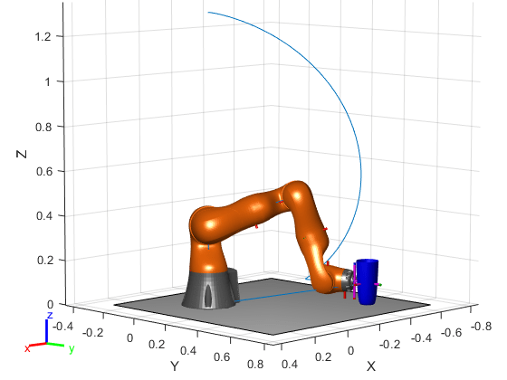
If you need to save the generated configuration to the mat file for later use, execute the following command:
save('lbr_trajectory.mat', 'tWaypoints', 'qWaypoints');