Hello, great Xia. Welcome to the FPGA technology Jianghu. The Jianghu is so big. It's fate to meet each other.
Today, I will bring you the design of Ethernet controller (MAC) based on FPGA. Due to the long length, it is divided into three parts. Today, I will bring the third and second part, the simulation, testing and summary of the program. Don't talk much, load the goods.
Hyperlinks to the first two articles are also given here:
Design of Ethernet controller (MAC) based on FPGA (Part I)
Design of Ethernet controller (MAC) based on FPGA (in)
Reading guide
At present, the Internet has greatly changed our production and life. Accordingly, in the research and development of embedded system, more and more attention is paid to network function. Embedded system is no longer limited to isolated control and processing units, but towards network integration, so as to realize the centralized control and information sharing of multiple systems.
The development and application of Ethernet technology in embedded system has become one of the technical hotspots in the current embedded research field. On the one hand, compared with traditional RS-485 and CAN, Ethernet is more high-speed and universal, and CAN also be directly connected with the Internet to provide a wider range of remote access; In addition, the properly tailored and optimized TCP/IP protocol stack CAN also fully meet the needs of industrial applications. On the other hand, it has obvious advantages over IEEE 1394.0 bus in terms of generic cabling and software transmission cost.
The embedded system based on Ethernet has good application prospects in the following aspects:
• industry: industrial control, network instruments, remote distributed data acquisition
• home automation: smart home, information appliances, home gateway
• business: remote sales platform, intelligent vending machine, public telephone card issuing system
• environmental protection: water source and air pollution monitoring, flood control system and water and soil quality monitoring, dam safety
• others: traffic management, vehicle navigation, automatic meter reading
Therefore, when using FPGA to design various embedded application systems, we need to consider providing Ethernet interface for the system. This chapter will implement an Ethernet controller (MAC) example through FPGA, and introduce the implementation process in detail.
Abstract of the third part: this part will introduce the simulation, testing and summary of the program, including the top-level program, external PHY chip simulation program, simulation results and other related contents.
4, Simulation and test of program
The main part of the program has been introduced above. In order to check whether the program realizes the preset function, it is necessary to write a simulation program.
The simulation program (Testbench) of Ethernet controller needs to simulate both ends of data communication at the same time: host (upper layer protocol) and external PHY chip. Therefore, the structure of the design simulation program is shown in Figure 12.
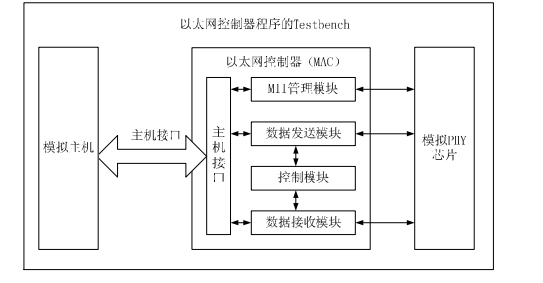
Figure 12 structure of Ethernet controller program Testbench
As can be seen from Figure 12, the simulation program should include: top-level program, simulated PHY program, simulated host program and Ethernet control program.
4.1 top level procedure
The top-level program is responsible for connecting all parts of the simulation program: simulation PHY program, simulation host program and Ethernet control program. At the same time, the top-level program needs to control the simulation. The main codes are as follows:
`include "eth_phy_defines.v"
`include "wb_model_defines.v"
`include "tb_eth_defines.v"
`include "eth_defines.v"
`include "timescale.v"
module tb_ethernet();

//Register and connection
  reg wb_clk;
  ......

//Connecting Ethernet controller
eth_top eth_top(
                .wb_clk_i(wb_clk), .wb_rst_i(wb_rst),
                .wb_adr_i(eth_sl_wb_adr_i[11:2]), .wb_sel_i(eth_sl_wb_sel_i), .wb_we_i(eth_sl_wb_we_i),
                .wb_cyc_i(eth_sl_wb_cyc_i), .wb_stb_i(eth_sl_wb_stb_i), .wb_ack_o(eth_sl_wb_ack_o),
                .wb_err_o(eth_sl_wb_err_o), .wb_dat_i(eth_sl_wb_dat_i), .wb_dat_o(eth_sl_wb_dat_o),
                .m_wb_adr_o(eth_ma_wb_adr_o), .m_wb_sel_o(eth_ma_wb_sel_o), .m_wb_we_o(eth_ma_wb_we_o), .m_wb_dat_i(eth_ma_wb_dat_i), .m_wb_dat_o(eth_ma_wb_dat_o), .m_wb_cyc_o(eth_ma_wb_cyc_o),
                .m_wb_stb_o(eth_ma_wb_stb_o), .m_wb_ack_i(eth_ma_wb_ack_i), .m_wb_err_i(eth_ma_wb_err_i),
                //send data
                .mtx_clk_pad_i(mtx_clk), .mtxd_pad_o(MTxD), .mtxen_pad_o(MTxEn), .mtxerr_pad_o(MTxErr),
                //Receiving data part
                .mrx_clk_pad_i(mrx_clk), .mrxd_pad_i(MRxD), .mrxdv_pad_i(MRxDV), .mrxerr_pad_i(MRxErr),
                .mcoll_pad_i(MColl), .mcrs_pad_i(MCrs),
                //Media independent interface module
                .mdc_pad_o(Mdc_O), .md_pad_i(Mdi_I), .md_pad_o(Mdo_O), .md_padoe_o(Mdo_OE),
                .int_o(wb_int)
                )

//PHY connection part
  assign Mdio_IO = Mdo_OE ? Mdo_O : 1'bz ;
  assign Mdi_I = Mdio_IO;

  integer phy_log_file_desc;

  eth_phy eth_phy(
                  .m_rst_n_i(!wb_rst),
                  // MAC send data
                  .mtx_clk_o(mtx_clk), .mtxd_i(MTxD), .mtxen_i(MTxEn), .mtxerr_i(MTxErr),
                  // MAC receive data
                  .mrx_clk_o(mrx_clk), .mrxd_o(MRxD), .mrxdv_o(MRxDV), .mrxerr_o(MRxErr),
                  .mcoll_o(MColl), .mcrs_o(MCrs),
                  //Media independent interface module
                  .mdc_i(Mdc_O), .md_io(Mdio_IO),
                  .phy_log(phy_log_file_desc)
                 );

// Connecting the host module
  integer host_log_file_desc;
  WB_MASTER_BEHAVIORAL wb_master(
                                  .CLK_I(wb_clk),
                                  .RST_I(wb_rst),
                                  .TAG_I({`WB_TAG_WIDTH{1'b0}}),
                                  .TAG_O(),
                                  .ACK_I(eth_sl_wb_ack_o),
                                  .ADR_O(eth_sl_wb_adr), // only eth_sl_wb_adr_i[11:2] used
                                  .CYC_O(eth_sl_wb_cyc_i),
                                  .DAT_I(eth_sl_wb_dat_o),
                                  .DAT_O(eth_sl_wb_dat_i),
                                  .ERR_I(eth_sl_wb_err_o),
                                  .RTY_I(1'b0), // inactive (1'b0)
                                  .SEL_O(eth_sl_wb_sel_i),
                                  .STB_O(eth_sl_wb_stb_i),
                                  .WE_O (eth_sl_wb_we_i),
                                  .CAB_O() // NOT USED for now!
                                  )

  assign eth_sl_wb_adr_i = {20'h0, eth_sl_wb_adr[11:2], 2'h0};
  ......

//initialization
  initial
  begin
  //Reset signal
  wb_rst = 1'b1;
  #423 wb_rst = 1'b0;
//Clear memory contents
  clear_memories;
  clear_buffer_descriptors;
  #423 StartTB = 1'b1;
  end

//Generate clock signal
  initial
  begin
  wb_clk=0;
  forever #15 wb_clk = ~wb_clk; // 2*10 ns -> 33.3 MHz
  end

  integer tests_successfull;
  integer tests_failed;
  reg [799:0] test_name; // used for tb_log_file
  reg [3:0] wbm_init_waits; // initial wait cycles between CYC_O and STB_O of WB Master
  reg [3:0] wbm_subseq_waits; // subsequent wait cycles between STB_Os of WB Master
  reg [2:0] wbs_waits; // wait cycles befor WB Slave responds
  reg [7:0] wbs_retries; // if RTY response, then this is the number of retries before ACK
  reg wbm_working; // tasks wbm_write and wbm_read set signal when working and resetit when stop working

//Start test content
  initial
  begin
  wait(StartTB); // Start testing
  //Initialize global variables
  tests_successfull = 0;
  tests_failed = 0;
  wbm_working = 0;
  wbm_init_waits = 4'h1;
  wbm_subseq_waits = 4'h3;
  wbs_waits = 4'h1;
  wbs_retries = 8'h2;
  wb_slave.cycle_response(`ACK_RESPONSE, wbs_waits, wbs_retries);

//Each task of the test
  test_note("PHY generates ideal Carrier sense and Collision signals for following tests");
  eth_phy.carrier_sense_real_delay(0);
  test_mac_full_duplex_transmit(0, 21); //Test data transmission in full duplex mode
  test_mac_full_duplex_receive(0, 13); //Test receiving data in full duplex mode
  test_mac_full_duplex_flow_control(0, 4); // Test the whole data flow
  test_note("PHY generates 'real delayed' Carrier sense and Collision signals for following
  tests");
  eth_phy.carrier_sense_real_delay(1);
// End test
  test_summary;
  $stop;
  end
The test content is executed through multiple test tasks. Limited by space, the contents of test tasks are not listed one by one.
4.2 external PHY chip simulation program
The simulation program simulates the simplified LXT971A chip (the external PHY chip of Inter company). PHY chip is connected to Ethernet controller through MIIM (media independent interface management module), so:
• when the Ethernet controller sends data to the PHY chip simulator, the PHY chip simulator controls the data transmission according to the protocol;
• when the PHY chip sends data to the Ethernet controller, the external PHY chip simulation program first generates the data to be transmitted according to the protocol requirements, and then sends it to the Ethernet controller.
The main codes of external PHY chip simulation program are as follows:
`include "timescale.v"
`include "eth_phy_defines.v"
`include "tb_eth_defines.v"
module eth_phy (m_rst_n_i, mtx_clk_o, mtxd_i, mtxen_i, mtxerr_i, mrx_clk_o, mrxd_o, mrxdv_o,
mrxerr_o,mcoll_o, mcrs_o,mdc_i, md_io, phy_log);

//Input / output signal
  input m_rst_n_i;
  ......

//Registers and connections
  reg control_bit15; // self clearing bit
  ......

// MIIM part of PHY chip simulation program
  ......

//initialization
  initial
  begin
    md_io_enable = 1'b0;
    respond_to_all_phy_addr = 1'b0;
    no_preamble = 1'b0;
  end

// Put the output in three states
  assign #1 md_io = (m_rst_n_i && md_io_enable) ? md_io_output : 1'  bz ;

//Register input
  always@(posedge mdc_i or negedge m_rst_n_i)
  begin
    if (!m_rst_n_i)
      md_io_reg <= #1 0;
    else
      md_io_reg <= #1 md_io;
  end

// Get PHY address, register address and data input, and shift the data to be output
// putting Data out and shifting
  always@(posedge mdc_i or negedge m_rst_n_i)
  begin
    if (!m_rst_n_i)
      begin
        phy_address <= 0;
        reg_address <= 0;
        reg_data_in <= 0;
        reg_data_out <= 0;
        md_io_output <= 0;
      end
    else
      begin
        if (md_get_phy_address)
          begin
            phy_address[4:1] <= phy_address[3:0]; // correct address is `ETH_PHY_ADDR
            phy_address[0] <= md_io;
          end
        if (md_get_reg_address)
          begin
            reg_address[4:1] <= reg_address[3:0];
            reg_address[0] <= md_io;
          end
        if (md_get_reg_data_in)
          begin
            reg_data_in[15:1] <= reg_data_in[14:0];
            reg_data_in[0] <= md_io;
          end
        if (md_put_reg_data_out)
          begin
            reg_data_out <= register_bus_out;
          end
        if (md_io_enable)
          begin
            md_io_output <= reg_data_out[15];
            reg_data_out[15:1] <= reg_data_out[14:0];
            reg_data_out[0] <= 1'b0;
          end
      end
  end

  assign #1 register_bus_in = reg_data_in; // md_put_reg_data_in - allows writing to a selected

  register
// Statistics of data transmitted through MIIM (media independent interface management module)
  always@(posedge mdc_i or negedge m_rst_n_i)
  begin
    if (!m_rst_n_i)
      begin
        if (no_preamble)
          md_transfer_cnt <= 33;
        else
          md_transfer_cnt <= 1;
          end
        else
          begin
            if (md_transfer_cnt_reset)
              begin
                if (no_preamble)
                  md_transfer_cnt <= 33;
                else
                  md_transfer_cnt <= 1;
                  end
                else if (md_transfer_cnt < 64)
                  begin
                    md_transfer_cnt <= md_transfer_cnt + 1'b1;
                  end
                else
                  begin
                    if (no_preamble)
                      md_transfer_cnt <= 33;
                    else
                      md_transfer_cnt <= 1;
                  end
            end
  end

// Transmission control of MIIM
  always@(m_rst_n_i or md_transfer_cnt or md_io_reg or md_io_rd_wr orphy_address or respond_to_all_phy_addr or no_preamble)
  begin
  #1;
  while ((m_rst_n_i) && (md_transfer_cnt <= 64))
  begin
// Reset signal
// Check header
    if (md_transfer_cnt < 33)
      begin
        #4 md_put_reg_data_in = 1'b0;
        if (md_io_reg !== 1'b1)
          begin
          #1 md_transfer_cnt_reset = 1'b1;
          end
        else
          begin
          #1 md_transfer_cnt_reset = 1'b0;
          end
  end
//Check start bit
    else if (md_transfer_cnt == 33)
      begin
        if (no_preamble)
          begin
          #4 md_put_reg_data_in = 1'b0;
        if (md_io_reg === 1'b0)
          begin
          #1 md_transfer_cnt_reset = 1'b0;
          end
        else
          begin
            #1 md_transfer_cnt_reset = 1'b1;
            //if ((md_io_reg !== 1'bz) && (md_io_reg !== 1'b1))
            if (md_io_reg !== 1'bz)
          begin
//error
            `ifdef VERBOSE
            $fdisplay(phy_log, "*E (%0t)(%m)MIIM - wrong first start bit (without preamble)",
            $time);
            `endif
            #10 $stop;
          end
    end
  end

  else // with preamble
          begin
            #4 ;
            `ifdef VERBOSE
            $fdisplay(phy_log, " (%0t)(%m)MIIM - 32-bit preamble received", $time);
            `endif
            // check start bit only if md_transfer_cnt_reset is inactive, because if
            // preamble suppression was changed start bit should not be checked
            if ((md_io_reg !== 1'b0) && (md_transfer_cnt_reset == 1'b0))
            begin
// error
              `ifdef VERBOSE
              $fdisplay(phy_log, "*E (%0t)(%m)MIIM - wrong first start bit", $time);
              `endif
              #10 $stop;
            end
          end
        end
      else if (md_transfer_cnt == 34)
        begin
        #4;
        if (md_io_reg !== 1'b1)
          begin
 // error
            #1;
            `ifdef VERBOSE
            if (no_preamble)
            $fdisplay(phy_log, "*E (%0t)(%m)MIIM - wrong second start bit (without preamble)",
            $time);
          else
              $fdisplay(phy_log, "*E (%0t)(%m)MIIM - wrong second start bit", $time);
              `endif
              #10 $stop;
            end
            else
            begin
              `ifdef VERBOSE
              if (no_preamble)
                #1 $fdisplay(phy_log, " (%0t)(%m)MIIM - 2 start bits received (without preamble)",$time);
              else
                #1 $fdisplay(phy_log, " (%0t)(%m)MIIM - 2 start bits received", $time);
              `endif
            end
          end
            // Register op code
            else if (md_transfer_cnt == 35)
            begin
              #4;
                if (md_io_reg === 1'b1)
                  begin
                  #1 md_io_rd_wr = 1'b1;
            end
                else
                  begin
                    #1 md_io_rd_wr = 1'b0;
                  end
            end
            else if (md_transfer_cnt == 36)
            begin
            #4;
            if ((md_io_reg === 1'b0) && (md_io_rd_wr == 1'b1))
            begin
            #1 md_io_rd_wr = 1'b1; // reading from PHY registers
            `ifdef VERBOSE
            $fdisplay(phy_log, " (%0t)(%m)MIIM - op-code for READING from registers", $time);
            `endif
            end
            else if ((md_io_reg === 1'b1) && (md_io_rd_wr == 1'b0))
            begin
            #1 md_io_rd_wr = 1'b0; // writing to PHY registers
            `ifdef VERBOSE
            $fdisplay(phy_log, " (%0t)(%m)MIIM - op-code for WRITING to registers", $time);
            `endif
            end
            else
            begin
            // Opcode error
            `ifdef VERBOSE
            #1 $fdisplay(phy_log, "*E (%0t)(%m)MIIM - wrong OP-CODE", $time);
            `endif
            #10 $stop;
  end

// Get PHY address
  begin
  #1 md_get_phy_address = 1'b1;
  end
  end
  else if (md_transfer_cnt == 41)
  begin
  #4 md_get_phy_address = 1'b0;
  // set the signal - get register address
  #1 md_get_reg_address = 1'b1;
  end
  // Get register address
  else if (md_transfer_cnt == 46)
  begin
  #4 md_get_reg_address = 1'b0;
  #1 md_put_reg_data_out = 1'b1;
  end
  ......

// Control of data transmission between PHY chip and Ethernet controller
// register
  reg mcoll_o;
  ......
//Initialize all registers
  initial
  begin
    mcrs_rx = 0;
    mcrs_tx = 0;
    task_mcoll = 0;
    task_mcrs = 0;
    task_mcrs_lost = 0;
    no_collision_in_half_duplex = 0;
    collision_in_full_duplex = 0;
    no_carrier_sense_in_tx_half_duplex = 0;
    no_carrier_sense_in_rx_half_duplex = 0;
    carrier_sense_in_tx_full_duplex = 0;
    no_carrier_sense_in_rx_full_duplex = 0;
    real_carrier_sense = 0;
  end

// Data conflict
  always@(m_rst_n_i or control_bit8_0 or collision_in_full_duplex or
  mcrs_rx or mcrs_tx or task_mcoll or no_collision_in_half_duplex)
  begin
    if (!m_rst_n_i)
      mcoll_o = 0;
    else
      begin
    if (control_bit8_0[8]) // full duplex
      begin
    if (collision_in_full_duplex) // collision is usually not asserted in full duplex
      begin
      mcoll_o = ((mcrs_rx && mcrs_tx) || task_mcoll);
      `ifdef VERBOSE
      if (mcrs_rx && mcrs_tx)
            $fdisplay(phy_log, " (%0t)(%m) Collision set in FullDuplex!", $time);
        if (task_mcoll)
          $fdisplay(phy_log, " (%0t)(%m) Collision set in FullDuplex from TASK!", $time);
      `endif
        end
      else
          begin
            mcoll_o = task_mcoll;
            `ifdef VERBOSE
            if (task_mcoll)
            $fdisplay(phy_log, " (%0t)(%m) Collision set in FullDuplex from TASK!", $time);
            `endif
          end
      end
          else // half duplex
          begin
          mcoll_o = ((mcrs_rx && mcrs_tx && !no_collision_in_half_duplex) ||task_mcoll);
            `ifdef VERBOSE
            if (mcrs_rx && mcrs_tx)
            $fdisplay(phy_log, " (%0t)(%m) Collision set in HalfDuplex!", $time);
            if (task_mcoll)
            $fdisplay(phy_log, " (%0t)(%m) Collision set in HalfDuplex from TASK!", $time);
            `endif
          end
     end
  end

//Carrier sense multiple access
  always@(m_rst_n_i or control_bit8_0 or carrier_sense_in_tx_full_duplex or
  no_carrier_sense_in_rx_full_duplex or
  no_carrier_sense_in_tx_half_duplex or
  no_carrier_sense_in_rx_half_duplex or
  mcrs_rx or mcrs_tx or task_mcrs or task_mcrs_lost)
  begin
    if (!m_rst_n_i)
      mcrs_o = 0;
  else
    begin
      if (control_bit8_0[8]) // full duplex
        begin
          if (carrier_sense_in_tx_full_duplex) // carrier sense is usually not asserted duringTX in full duplex
            mcrs_o = ((mcrs_rx && !no_carrier_sense_in_rx_full_duplex) ||
            mcrs_tx || task_mcrs) && !task_mcrs_lost;
          else
            mcrs_o = ((mcrs_rx && !no_carrier_sense_in_rx_full_duplex) ||
            task_mcrs) && !task_mcrs_lost;
         end
      else // half duplex
        begin
          mcrs_o = ((mcrs_rx && !no_carrier_sense_in_rx_half_duplex) ||
          (mcrs_tx && !no_carrier_sense_in_tx_half_duplex) ||
          task_mcrs) && !task_mcrs_lost;
        end
    end
  end

// Ethernet controller sends data and PHY chip receives data
//register
  reg [7:0] tx_mem [0:4194303]; // 4194304 is all the addresses that can be provided by the 22 bit address line, and each address is 8 bits
  ......

//Send data control
  always@(posedge mtx_clk_o)
  begin
// Save the data and check the basic frame data
    if (!m_rst_n_i)
      begin
        tx_cnt <= 0;
        tx_preamble_ok <= 0;
        tx_sfd_ok <= 0;
        tx_len <= 0;
        tx_len_err <= 0;
      end
    else
      begin
        if (!mtxen_i)
          begin
            tx_cnt <= 0;
          end
        else
          begin
//A counter that sends four byte data
            tx_cnt <= tx_cnt + 1;
//Set the initialization value and check the header of the first four byte data
        if (tx_cnt == 0)
            begin
              `ifdef VERBOSE
              $fdisplay(phy_log, " (%0t)(%m) TX frame started with tx_en set!", $time);
              `endif
                if (mtxd_i == 4'h5)
                    tx_preamble_ok <= 1;
                else
                    tx_preamble_ok <= 0;
                    tx_sfd_ok <= 0;
                    tx_byte_aligned_ok <= 0;
                    tx_len <= 0;
                    tx_len_err <= 0;
              end
// Check header
                  if ((tx_cnt > 0) && (tx_cnt <= 13))
                    begin
                      if ((tx_preamble_ok != 1) || (mtxd_i != 4'h5))
                      tx_preamble_ok <= 0;
                    end
  // Check SFD
                if (tx_cnt == 14)
                    begin
                      `ifdef VERBOSE
                 if (tx_preamble_ok == 1)
                    $fdisplay(phy_log, " (%0t)(%m) TX frame preamble OK!", $time);
                  else
                    $fdisplay(phy_log, "*E (%0t)(%m) TX frame preamble NOT OK!", $time);
                    `endif
                  if (mtxd_i == 4'h5)
                      tx_sfd_ok <= 1;
                  else
                      tx_sfd_ok <= 0;
                      end
                  if (tx_cnt == 15)
                    begin
                      if ((tx_sfd_ok != 1) || (mtxd_i != 4'hD))
                        tx_sfd_ok <= 0;
                    end
  // Control storage address, data type / length, data content and FCS to send data buffer
                  if (tx_cnt > 15)
                    begin
                    if (tx_cnt == 16)
                      begin
                        `ifdef VERBOSE
                    if (tx_sfd_ok == 1)
                        $fdisplay(phy_log, " (%0t)(%m) TX frame SFD OK!", $time);
                      else
                          $fdisplay(phy_log, "*E (%0t)(%m) TX frame SFD NOT OK!", $time);
                        `endif
                          end
                    if (tx_cnt[0] == 0)
                          begin
                            tx_mem_data_in[3:0] <= mtxd_i; // storing LSB nibble
                            tx_byte_aligned_ok <= 0; // if transfer will stop after this, then there was driblenibble
                          end
                      else
                  begin
                    tx_mem[tx_mem_addr_in[21:0]] <= {mtxd_i, tx_mem_data_in[3:0]}; // storing data into
                    tx memory
                    tx_len <= tx_len + 1; // enlarge byte length counter
                    tx_byte_aligned_ok <= 1; // if transfer will stop after this, then transfer is byte
                    alligned
                    tx_mem_addr_in <= tx_mem_addr_in + 1'b1;
                  end
                    if (mtxerr_i)
                      tx_len_err <= tx_len;
          end
      end
  end

//Generating a carrier signal for transmitting data
                if (!m_rst_n_i)
                      begin
                          mcrs_tx <= 0;
                          mtxen_d1 <= 0;
                          mtxen_d2 <= 0;
                          mtxen_d3 <= 0;
                          mtxen_d4 <= 0;
                          mtxen_d5 <= 0;
                          mtxen_d6 <= 0;
                      end
                else
                      begin
                          mtxen_d1 <= mtxen_i;
                          mtxen_d2 <= mtxen_d1;
                          mtxen_d3 <= mtxen_d2;
                          mtxen_d4 <= mtxen_d3;
                          mtxen_d5 <= mtxen_d4;
                          mtxen_d6 <= mtxen_d5;
                          if (real_carrier_sense)
                          mcrs_tx <= mtxen_d6;
                else
                   mcrs_tx <= mtxen_i;
                        end
            end

  `ifdef VERBOSE
  reg frame_started;

  initial
  begin
    frame_started = 0;
  end

  always@(posedge mtxen_i)
  begin
    frame_started <= 1;
  end

  always@(negedge mtxen_i)
  begin
    if (frame_started)
      begin
        $fdisplay(phy_log, " (%0t)(%m) TX frame ended with tx_en reset!", $time);
        frame_started <= 0;
      end
  end

  always@(posedge mrxerr_o)
  begin
    $fdisplay(phy_log, " (%0t)(%m) RX frame ERROR signal was set!", $time);
  end
  `endif
  ......
endmodule
4.3 simulation results
As shown in Figure 13, it is the test of data transmission in full duplex mode. The highlighted MTxD in the figure is the data output of Ethernet controller.
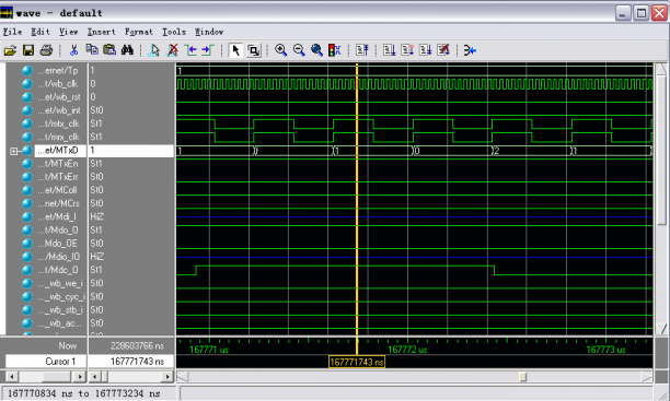
Fig. 13 test results of transmitting data in full duplex mode
As shown in Figure 14, it is the test of receiving data in full duplex mode. The MRxD highlighted in the figure is the input of data received by Ethernet controller.

Fig. 14 test results of received data in full duplex mode
Figure 15 shows the test results of the whole process of data transmission and reception in full duplex mode. The highlighted MTxD and MRxD in the figure are the output and input ports of Ethernet controller for transmitting and receiving data.
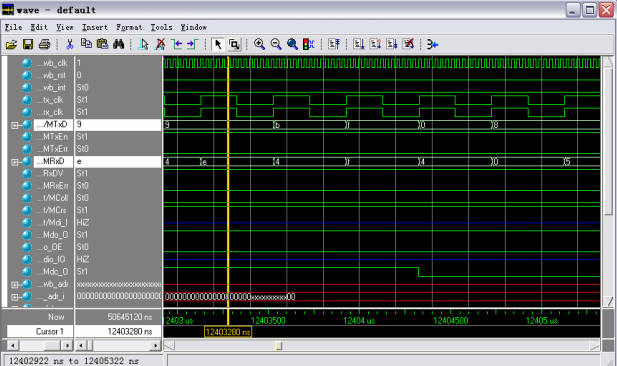
FIG. 15 test results of the whole process of data transmission and reception in full dual mode
FIG. 16 shows the test results of the whole process of transmitting and receiving data in half duplex mode.
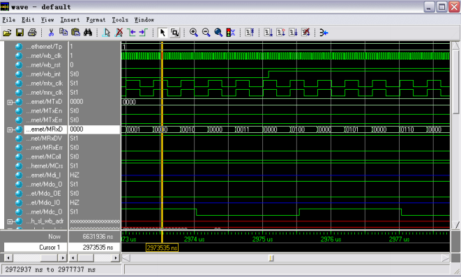
FIG. 16 test results of the whole process of sending and receiving data in half duplex mode
5, Summary
This paper introduces an example of Ethernet controller (MAC). Firstly, the basic principle of Ethernet is introduced, and then the main structure of Ethernet controller program and the implementation process of main functional modules are introduced. Finally, a test program is used to verify whether the function of the program meets the requirements. This chapter provides a useful scheme for readers to design their own Ethernet controller, and helps to deepen their understanding of Ethernet protocol.
This is the end of this article. Great Xia, goodbye! ENDThe follow-up will be continuously updated, bringing installation related design tutorials such as Vivado, ISE, Quartus II and candence, learning resources, project resources, good article recommendations, etc. I hope you will continue to pay attention.
Heroes, the Jianghu is so big. Continue to wander. May everything be well. See you again!