preface
Use tools
- Punctual atom STM32F103RCTb MINI development board
- 4PIN-OLED
- KEIL5
- FlyMcu
- PCtoLCD2002 (mold taking software)
Final effect and connection
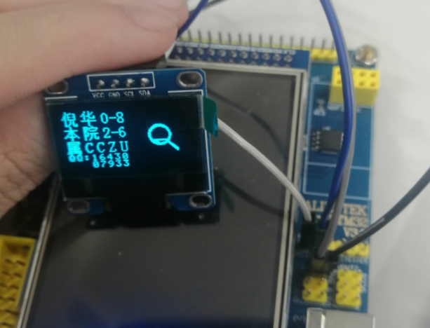
VCC--3.3V
GND--GND
SCL--PC11
SDA--PC12
Note: This article does not explain the basic principles of OLED and IIC, but only considers the use and implementation functions.
code
KEIL document overview
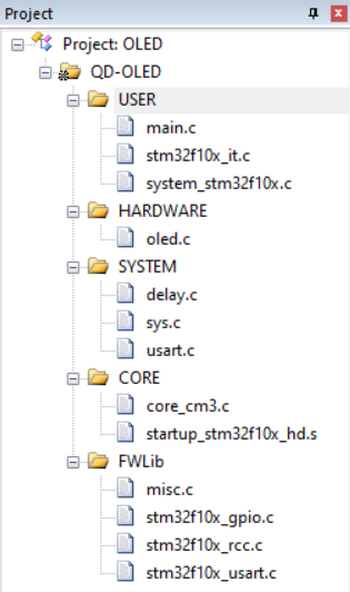
In the above file, main C contains the main function, OLED C contains IIC underlying code and OLED display.
Of course h file, where BMP h contains the modulo hexadecimal code of BMP picture, OLED h contains definitions of IIC pin and OLED screen, oledfont h contains ASCALL code and self-defined Chinese characters.
Others are official documents and are not prepared separately.
critical code
oled. IIC pin definition in H
If you want to modify the pins used, set GPIOC and GPIO_Pin_11 and GPIO_Pin_12 can be changed to corresponding, and no other changes need to be made.
#define OLED_SCLK_Clr() GPIO_ResetBits(GPIOC,GPIO_Pin_11)//CLK
#define OLED_SCLK_Set() GPIO_SetBits(GPIOC,GPIO_Pin_11)

#define OLED_SDIN_Clr() GPIO_ResetBits(GPIOC,GPIO_Pin_12)//DIN
#define OLED_SDIN_Set() GPIO_SetBits(GPIOC,GPIO_Pin_12)

#define OLED_CMD  0 	// Write command
#define OLED_DATA 1 	// Write data

/*In OLED C initializes SSD1306 and related procedures
 	GPIO_InitTypeDef  GPIO_InitStructure;

	RCC_APB2PeriphClockCmd(RCC_APB2Periph_GPIOC, ENABLE);
	GPIO_InitStructure.GPIO_Pin = GPIO_Pin_11|GPIO_Pin_12;
 	GPIO_InitStructure.GPIO_Mode = GPIO_Mode_Out_PP;
	GPIO_InitStructure.GPIO_Speed = GPIO_Speed_50MHz;
 	GPIO_Init(GPIOC, &GPIO_InitStructure);
 	GPIO_SetBits(GPIOC,GPIO_Pin_11|GPIO_Pin_12);
*/
display string
//The first parameter is x coordinate (0-128); The second parameter is y coordinate (0-8);
//The third is ASCALL code, which is' A 'when chr = 65; The fourth parameter is the text size, which is only 12 / 16.
void OLED_ShowChar(u8 x,u8 y,u8 chr,u8 Char_Size)
{
	unsigned char c=0,i=0;
		c=chr-' ';//Get the offset value
		if(x>Max_Column-1){x=0;y=y+2;}
		if(Char_Size ==16)
			{
			OLED_Set_Pos(x,y);
			for(i=0;i<8;i++)
			OLED_WR_Byte(F8X16[c*16+i],OLED_DATA);
			OLED_Set_Pos(x,y+1);
			for(i=0;i<8;i++)
			OLED_WR_Byte(F8X16[c*16+i+8],OLED_DATA);
			}
			else {
				OLED_Set_Pos(x,y);
				for(i=0;i<6;i++)
				OLED_WR_Byte(F6x8[c][i],OLED_DATA);

			}
}
Display number
//The first parameter is x coordinate (0-128); The second parameter is y coordinate (0-8);
//The third num is a number; The fourth parameter is numeric length; The fifth parameter is the number size, which is only 12 / 16.
void OLED_ShowNum(u8 x,u8 y,u32 num,u8 len,u8 size2)
{
	u8 t,temp;
	u8 enshow=0;
	for(t=0;t<len;t++)
	{
		temp=(num/oled_pow(10,len-t-1))%10;
		if(enshow==0&&t<(len-1))
		{
			if(temp==0)
			{
				OLED_ShowChar(x+(size2/2)*t,y,' ',size2);
				continue;
			}else enshow=1;

		}
	 	OLED_ShowChar(x+(size2/2)*t,y,temp+'0',size2);
	}
}
display string
//The first parameter is x coordinate (0-128); The second parameter is y coordinate (0-8);
//The third is a string; The fourth parameter is the character size, which is only 12 / 16.
void OLED_ShowString(u8 x,u8 y,u8 *chr,u8 Char_Size)
{
	unsigned char j=0;
	while (chr[j]!='\0')
	{		OLED_ShowChar(x,y,chr[j],Char_Size);
			x+=8;
		if(x>120){x=0;y+=2;}
			j++;
	}
}
Display Chinese characters
//The first parameter is x coordinate (0-128); The second parameter is y coordinate (0-8);
//The third is the Chinese character to be input, in oledfont Defined in H.
void OLED_ShowCHinese(u8 x,u8 y,u8 no)
{
	u8 t,adder=0;
	OLED_Set_Pos(x,y);
    for(t=0;t<16;t++)
		{
				OLED_WR_Byte(Hzk[2*no][t],OLED_DATA);
				adder+=1;
     }
		OLED_Set_Pos(x,y+1);
    for(t=0;t<16;t++)
			{
				OLED_WR_Byte(Hzk[2*no+1][t],OLED_DATA);
				adder+=1;
      }
}
Show BMP picture
//The first parameter is the starting x0 coordinate (0-128); The second parameter is the starting y0 coordinate (0-8);
//The third parameter is the end x1 coordinate (0-128); The fourth parameter is the end y1 coordinate (0-8);
//The fifth is the picture to be input.
void OLED_DrawBMP(unsigned char x0, unsigned char y0,unsigned char x1, unsigned char y1,unsigned char BMP[])
{
unsigned int j=0;
unsigned char x,y;
if(y1%8==0) y=y1/8;
else y=y1/8+1;
for(y=y0;y<y1;y++)
{
OLED_Set_Pos(x0,y);
for(x=x0;x<x1;x++)
{
OLED_WR_Byte(BMP[j++],OLED_DATA);
}
}
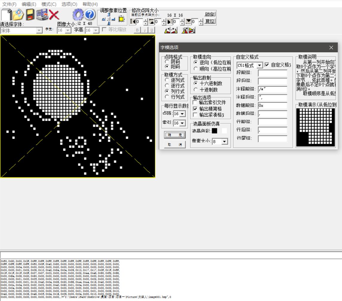
} Use of mold taking software
Software settings
1. Select Yin code and Yang code to see the effect you need.
2. If column expression is used, OLED_ x1-x0 of drawbmp function is the first parameter of image size. If determinant is used, OLED_ x1-x0 of drawbmp is the second parameter of image size.
3. Reverse direction shall be adopted for formwork taking.
4. Select C51 format for custom format.
The effect drawing of negative code, column type, reverse and C51 is as follows:
Effect drawing of code burning:
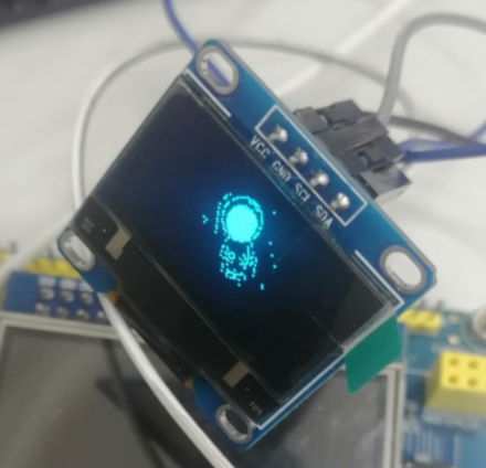
Dynamic graph implementation
Like the above steps of displaying BMP diagram, the difference is that it needs to be taken out one by one for display, which is very troublesome.
Sometimes, after the GIF map is directly taken into the BMP map, the tone will become very light, As shown on the right (it has something). You can first use Python program to convert GIF picture into PNG picture. If the picture is not black background, you need to use the picture provided by windows to reverse the color to black background, and then convert it into bmp picture, such as the effect in the left picture. After taking the effect in the left picture, take the mold, put it into the array, and use the for loop to achieve the effect. There is no need for delay.
Due renderings: