as everyone knows... I have another bad flight control. I took it to repair, and then I wanted to make this one. Send a link. I think it's very interesting after reading it! It can be sold to the people who shoot still life!
Here is an analysis of the scheme. When the dog licks the Mianshan, the chicken pecks the Mishan, and the candle burns out the iron 🔒, I'll do it.

My head is so beautiful
https://www.bilibili.com/video/BV15T4y1g7gt?p=1&share_medium=iphone&share_plat=ios&share_source=GENERIC&share_tag=s_i×tamp=1640536319&unique_k=c1FRrKK
Location of station B
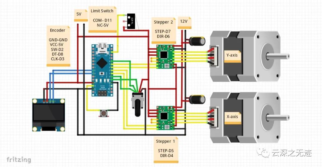
The core of the circuit is the stepping motor, which gives different degrees of freedom. A4988 is the driving chip.
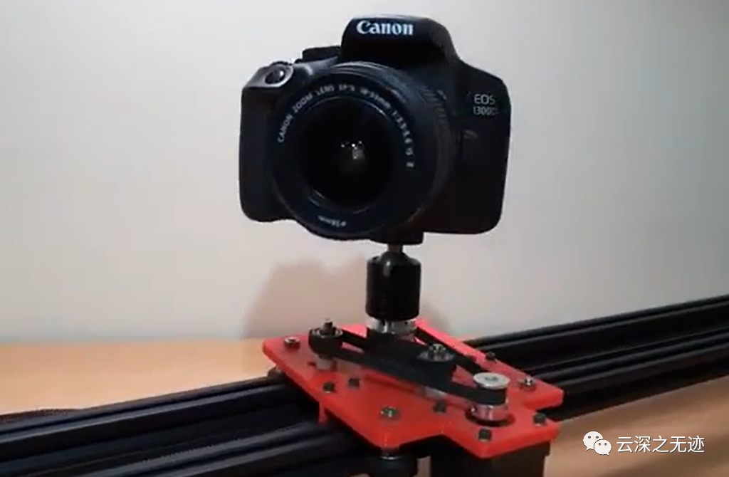
Installed appearance
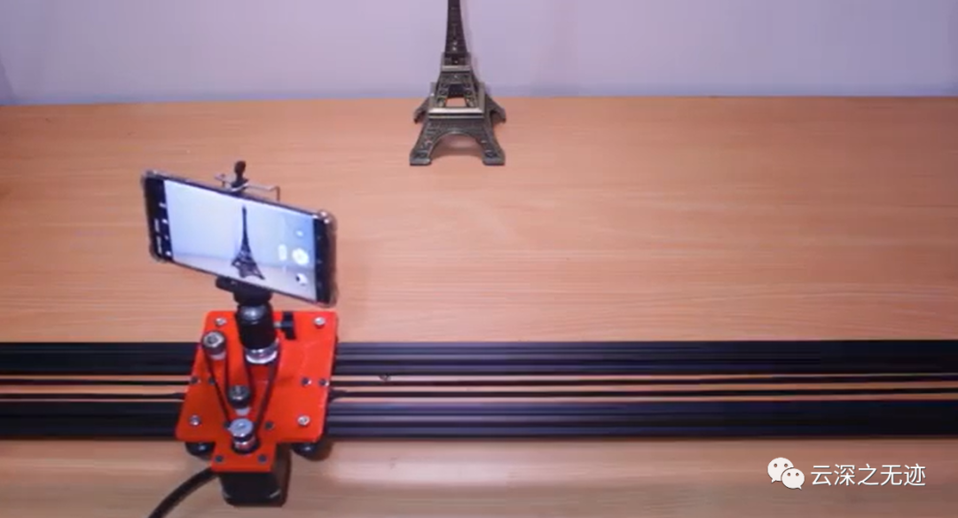
Holding a mobile phone to shoot

Run a scene
https://www.youtube.com/watch?v=qub5chyIQ0s
This link is the location of YouTube
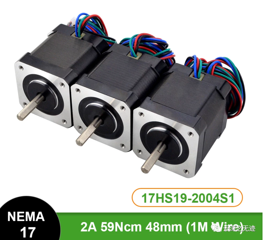
Three stepper motors are used

Adjusting direction of chip
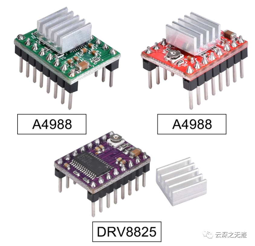
I used to use it when I was a small printer
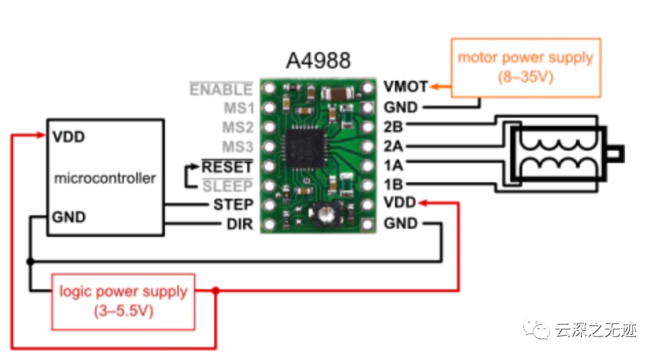
Recommended wiring
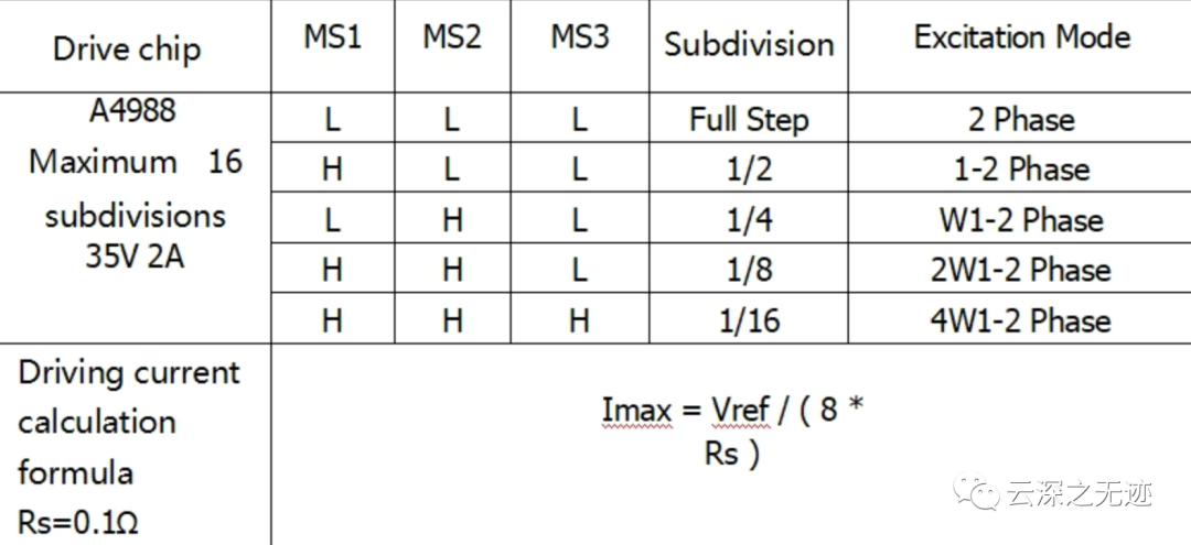
Forward and reverse when using
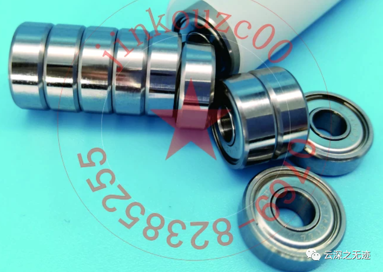
Bearings to be used
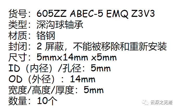
Remember the name and buy it
   const int interruptA = 0; / / Interrupt 0 (pin 2)

   const int interruptB = 1; / / Interrupt 1 (pin 3)

   int CLK = 2; / / PIN2

   int DAT = 3; / / PIN3

   int BUTTON = 4; / / PIN4

   int LED1 = 5; / / PIN5

   int LED2 = 6; / / PIN6

   int COUNT = 0;

   void setup ()

   {

   attachInterrupt (interruptA, RoteStateChanged, FALLING);

   / / AttachInterrupt (interruptB, buttonState, FALLING);

   pinMode (CLK, INPUT);

   digitalWrite (2, HIGH); / / Pull High Restance

   pinMode (DAT, INPUT);

   digitalWrite (3, HIGH); / / Pull High Restance

   pinMode (BUTTON, INPUT);

   digitalWrite (4, HIGH); / / Pull High Restance

   pinMode (LED1, OUTPUT);

   pinMode (LED2, OUTPUT);

   Serial.begin (9600);

   }

   void loop ()

   {

   if (! (digitalRead (BUTTON)))

   {

   COUNT = 0;

   Serial.println ("STOP COUNT = 0");

   digitalWrite (LED1, LOW);

   digitalWrite (LED2, LOW);

   delay (2000);

   }

   Serial.println (COUNT);

   }

   / / -------------------------------------------

   void RoteStateChanged () / / When CLK FALLING READ DAT

   {

   if (digitalRead (DAT)) / / When DAT = HIGH IS FORWARD

   {

   COUNT;

   digitalWrite (LED1, HIGH);

   digitalWrite (LED2, LOW);

   delay (20);

   }

   else / / When DAT = LOW IS BackRote

   {

   COUNT -;

   digitalWrite (LED2, HIGH);

   digitalWrite (LED1, LOW);

   delay (20);

   }
   }
Because the article has been written for too long... I don't know what my code is for
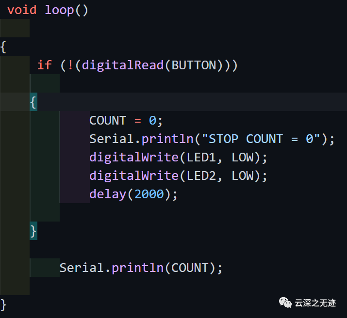
It's probably reading the value of a knob to control what
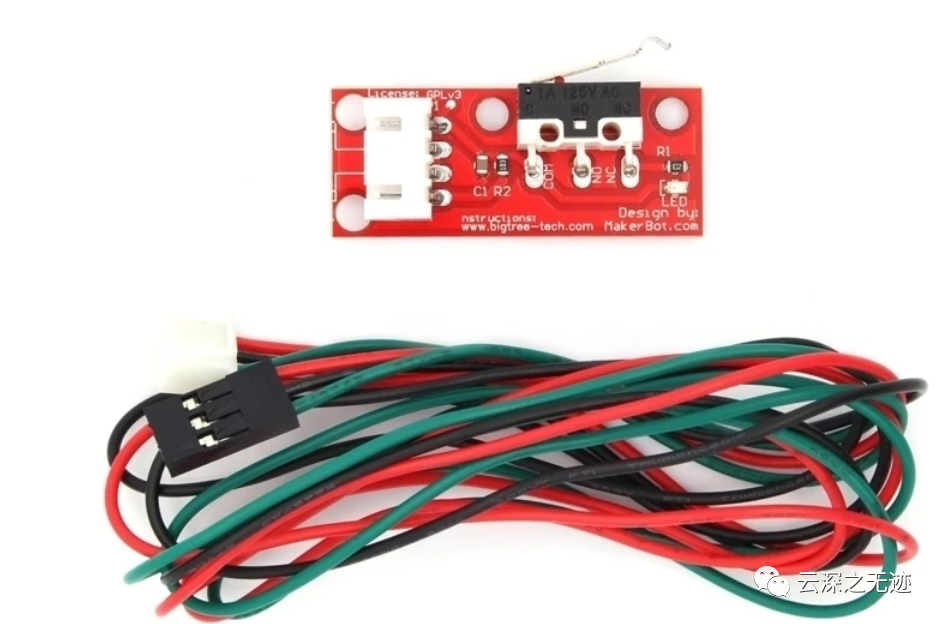
The limit switch will be triggered when the machine reaches the edge. Power off
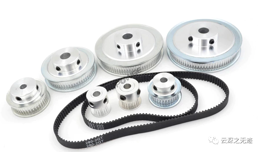
This is called synchronous pulley set
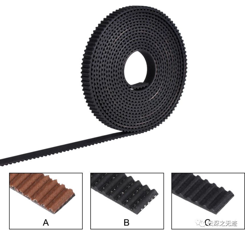
This is called a timing belt
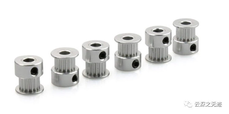
Synchronous wheel
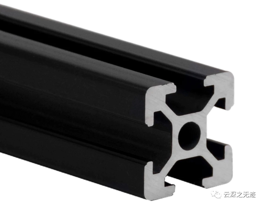
Linear Guide
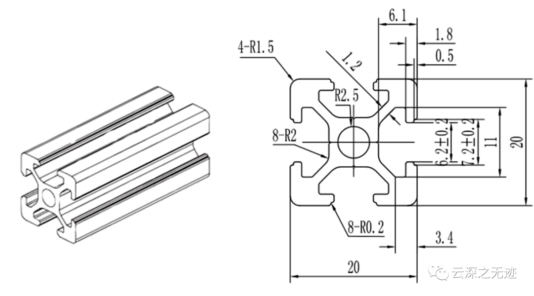
What is this called mechanical assembly drawing?
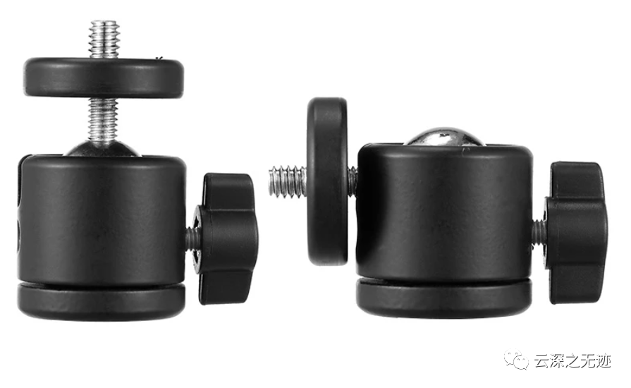
Mini spherical PTZ
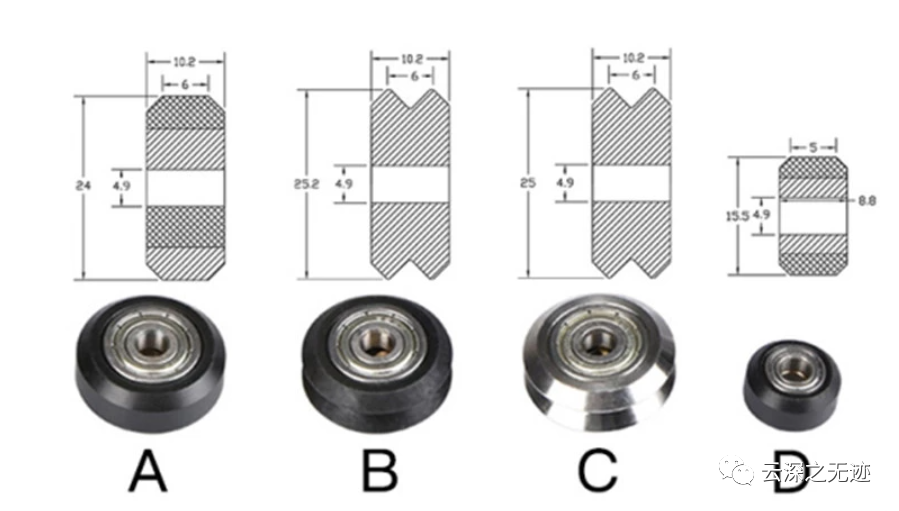
Delin wheel
When reading here, professional photographers have some new requirements:
- Add acceleration control input.
- The option of the third motor is very useful for the tilt function.
- A menu with optional function, which can beat continuously between point a and point B to cycle shooting
4. As an upgrade, the AS5600 encoder module with magnet mark position will be great. Manually positioning the camera is always a better choice for photographers.
5. Finally, you can also expand the code of the camera lens focusing motor.
https://www.airspayce.com/mikem/arduino/AccelStepper/index.html
Here is the motor library used in the project. Compared with the previous library, it has added many interesting functions.

Some functions
What is calculated in this library is: steps per second instead of radians per second (because we don't know the step angle of the motor). Calculate the initial step interval of the first step according to the required acceleration. In subsequent steps, calculate the shorter step interval according to the previous step until the maximum speed is reached.

There are two classes in this library. One is to control stepping motors with acceleration function, and the other is to control multiple stepping motors.
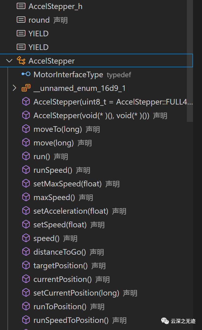
Single acceleration stepping motor
https://www.embedded.com/generate-stepper-motor-speed-profiles-in-real-time/
The stepping motor control algorithm in this paper is not random:
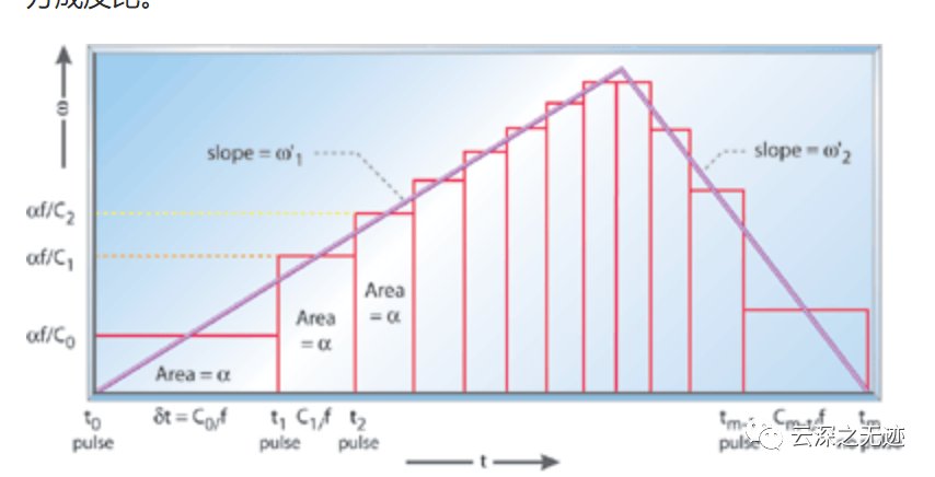
But there is a complete theoretical basis
Because of the competition, I need to use stepping motor, so the source code of this piece needs to be analyzed.

Four pins are used for setting
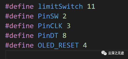
Actually, it uses five feet
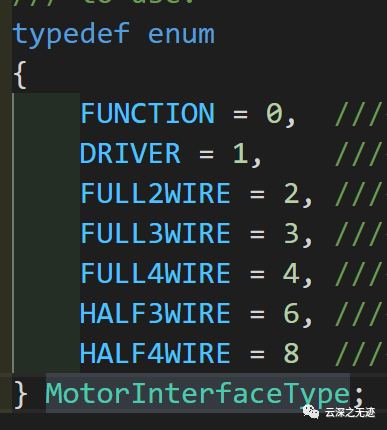
Interface type of motor
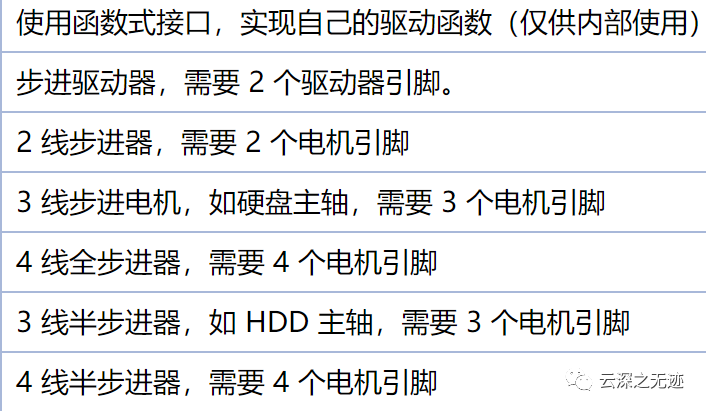
Basically corresponding

Direction of rotation
    AccelStepper
    (
    uint8_t interface = AccelStepper::FULL4WIRE,
    uint8_t pin1 = 2,
    uint8_t pin2 = 3,
    uint8_t pin3 = 4,
    uint8_t pin4 = 5,
    bool enable = true);
Constructor: you can have multiple steppers at the same time, all of which move at different speeds and accelerations, provided you call their run() function at enough frequent intervals.

This is the run function. Pay attention! This library is an open-loop controller, so which position is approximate
http://www.airspayce.com/mikem/arduino/AccelStepper/classAccelStepper.html

These are the creation of objects
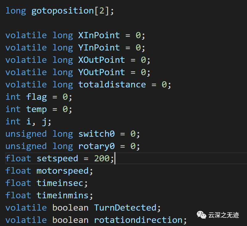
Related variable definitions
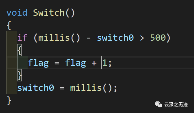
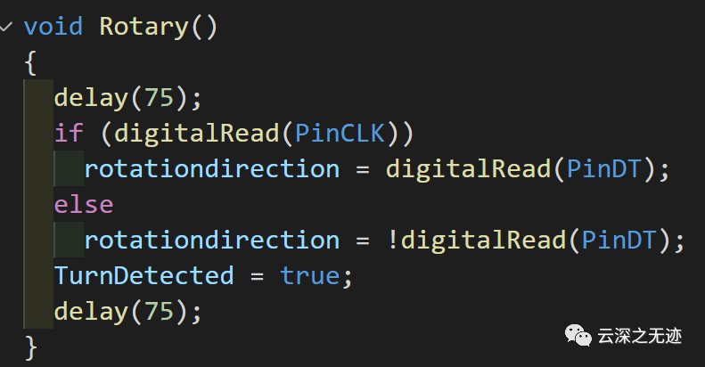
Function switching
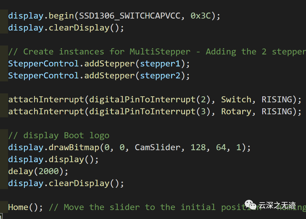
Screen start, stepper motor start, display
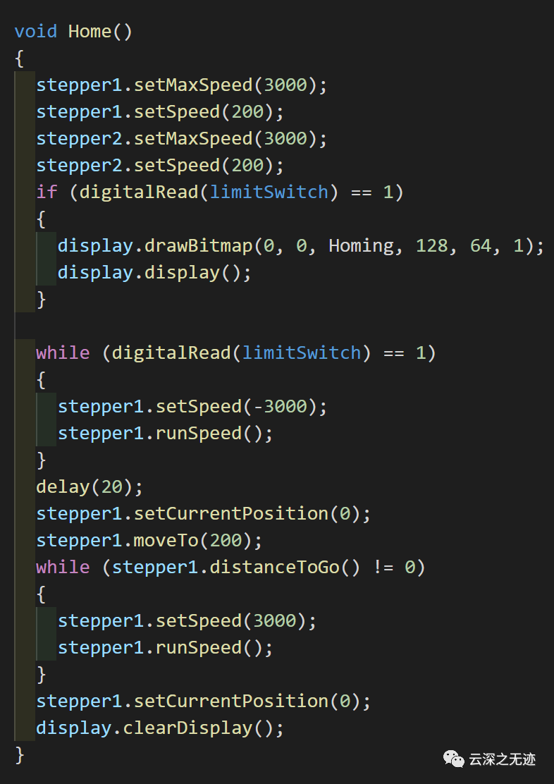
home function, here is the starting position, the code is simple
The remaining logic is simple, so I won't write it. The key is the use of this library:
http://www.airspayce.com/mikem/arduino/AccelStepper/classAccelStepper.html
In a project I am currently working on, there are also motors, but they are also open-loop. I think for the accuracy of this control, closed-loop control should be used.
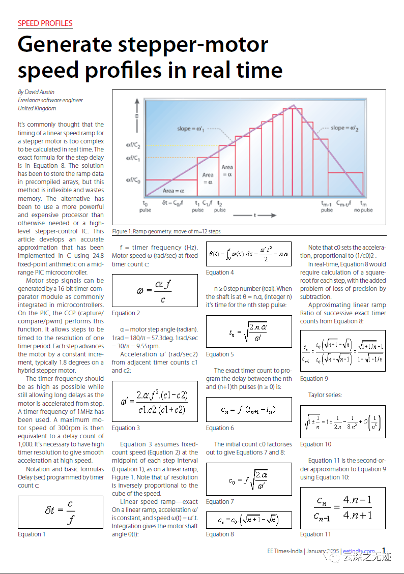
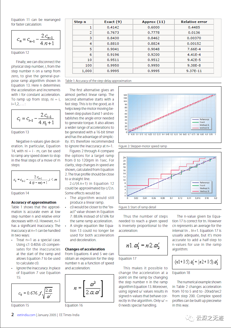

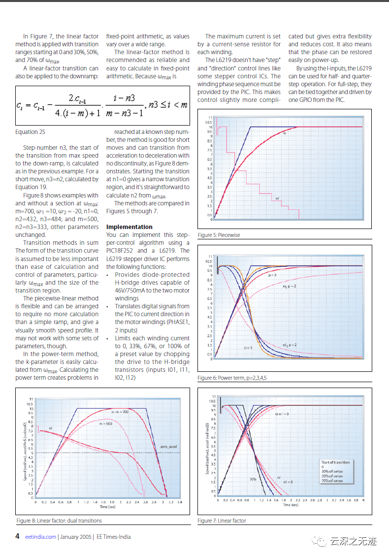
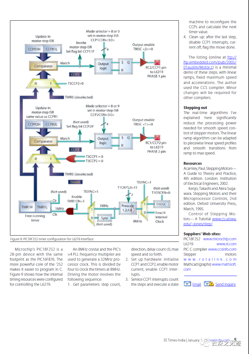
This is the algorithm used in our library.