VGA register
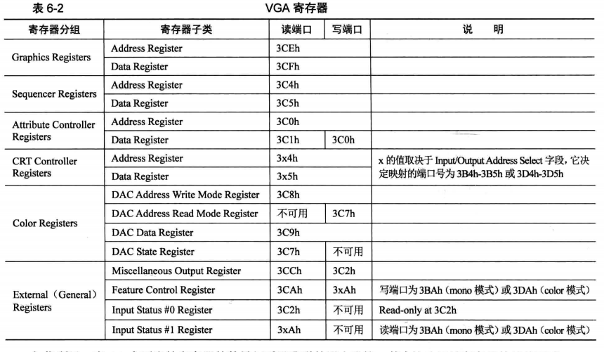
The reason why register subclasses are divided into Address Register and Data Register: there will be multiple registers under a register group. To operate on one of them, use the content of Address Register to indicate the subscript of this register in the register array, and use Data Register as the substitute of this register, Read and write operations to the Data Register can act indirectly on this register.
The port addresses of AR and DR in the CRT Controller Registers group are special. Their port addresses are not fixed, but contain x. the value of x depends on the Input/Output Address Select field in the Miscellaneous Output Register, i.e. I/OAS.
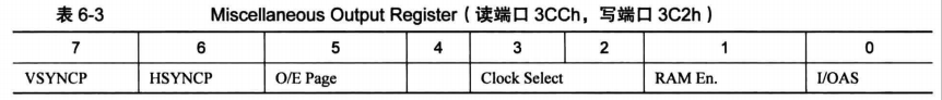
When this bit is 0, the value of x is B; When this bit is 1, x takes D.
The default is 1.
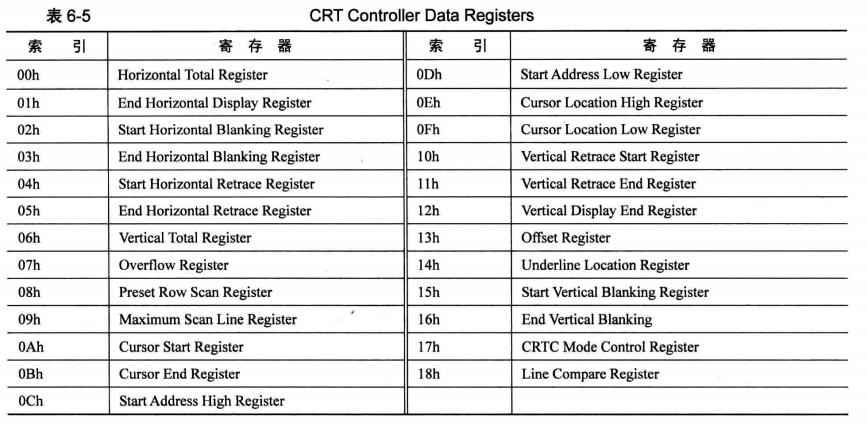
The indexes and their corresponding registers in the CRT Controller Registers register group are as follows:
Print a single character
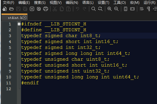
data type
Macro definition of some data types.
Overall process
The overall processing flow is as follows:
- Backup register field.
- Gets the cursor coordinate value as the position of the next printable character.
- Gets the character to be printed.
- Judge whether the character is a control character. If it is one of carriage return character, line feed character and backspace character, enter the corresponding processing flow; Otherwise, it will be processed as visible characters and output.
- Determine whether scrolling display is required.
- Update the coordinate value of the cursor to point to the position of the next printed character.
- Restore the register field and exit.
All of the following functions are in print S, split and explain.
put_char
TI_GDT equ  0
RPL0  equ   0
SELECTOR_VIDEO equ (0x0003<<3) + TI_GDT + RPL0

[bits 32]
section .text
;------------------------   put_char   -----------------------------
;Function description:Write one character in the stack to the cursor
;-------------------------------------------------------------------
global put_char
put_char:
   pushad	   ;Backup 32-bit register environment
   ;Need to be guaranteed gs Select a subset for the correct video segment in,To be on the safe side,For each print gs assignment
   mov ax, SELECTOR_VIDEO	       ; You cannot send an immediate value directly into the segment register
   mov gs, ax

;;;;;;;;;  Gets the current cursor position ;;;;;;;;;
   ;Get the upper 8 bits first
   mov dx, 0x03d4  ;Index register
   mov al, 0x0e	   ;The upper 8 bits used to provide the cursor position
   out dx, al
   mov dx, 0x03d5  ;By reading and writing data port 0 x3d5 To get or set the cursor position
   in al, dx	   ;The high 8 bits of the cursor position are obtained
   mov ah, al

   ;Get the lower 8 bits
   mov dx, 0x03d4
   mov al, 0x0f
   out dx, al
   mov dx, 0x03d5
   in al, dx

   ;Save cursor in bx
   mov bx, ax
   ;The following line is to get the characters to be printed in the stack
   mov ecx, [esp + 36]	      ;pushad Press in 4×8=32 byte,Plus 4 bytes of the return address of the calling function,so esp+36 byte
   cmp cl, 0xd				  ;CR Is 0 x0d,LF Is 0 x0a
   jz .is_carriage_return
   cmp cl, 0xa
   jz .is_line_feed

   cmp cl, 0x8				  ;BS(backspace)of asc The code is 8
   jz .is_backspace
   jmp .put_other
;;;;;;;;;;;;;;;;;;
The printing principle is to write the video memory directly. Video segment selection and intra segment offset are required to operate the video segment in memory.
- The first to third lines: define the selector of the video segment.
- Line 12: use the pushad instruction to back up all 32-bit registers. The stack pressing order is EAX, ECX, EDX, EBX, ESP, EBP, ESI and EDI.
- Lines 14 and 15: assign value to segment register gs to ensure that the value in GS is the correct segment selector before writing to video memory.
- Lines 17 to 34: get the cursor position. The cursor position is one-dimensional, such as the window size of 80 * 25, which can accommodate 2000 characters, so the value of cursor position is 0 ~ 1999. The lower 8 bits and the upper 8 bits of the cursor position are placed in the two registers indexed 0EH and 0FH in CRT Controller Registers respectively. Take the upper 8 bits as an example: first write the index 0x0EH to the Address Register with port address 0x03D4, and then read the Data Register with port address 0x03D5 to obtain the upper 8 bits of the cursor and save it to the upper 8 bits of the ah register. The same is true for the lower 8 bits, and then copy the cursor position into the bx register.
- Line 36: get the ASCII code of the character to be printed. The calling rule is to stack the ASCII code of one character, and then call put_ When calling the char function, the return address of 4B will be pressed on the stack, and the pushad instruction is used in the function to press the register data of 8 4b, a total of 32B, so the ASCII code of the character to be printed is offset by 36B at the top of the stack.
- Lines 37 to 44: judge the ASCII characters (enter, line feed, backspace, visible characters?) And jump to the corresponding processing function.