catalogue
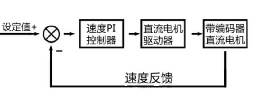
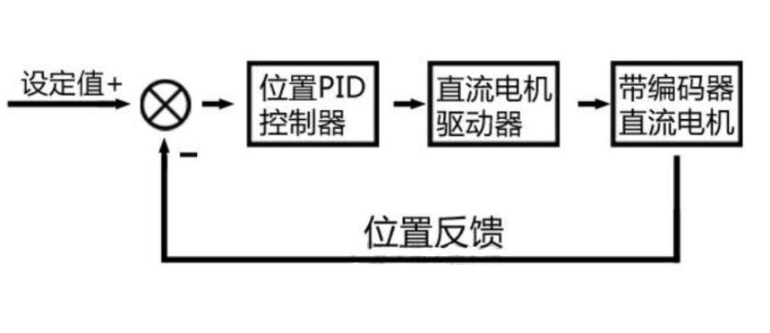
1. Therefore, the PID is roughly the block diagram
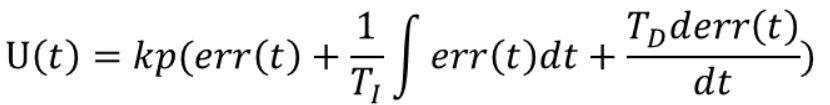
2. The formula of pid controller is
4. The hardware adopted is as follows (already in the open source of Lichuang)
6. Software program configuration
7. Parameter adjustment process record
Cascade control system It is one of the effective methods to improve control quality and has been widely used in process control. so-called Cascade control That is, two controllers work in series, the output of the outer loop controller is used as the set value of the inner loop controller, and the output of the inner loop controller is used to operate the control valve, so as to have a better control effect on the controlled quantity of the outer loop. Such a control system is called a cascade system. PID cascade control is that both controllers in cascade control are PID controller.
Limited to time and space, this article only records the sensory parameter adjustment by using the general pid method. When you go home, you will have time to add the improved pid to try the effect

Paste the principle first
PID control is the proportional, integral and differential control of deviation. PID consists of three units, namely proportional (P) unit, integral (I) unit and differential (D) unit. In engineering practice, P is generally necessary, so many combined PID controllers are derived, such as PD, PI, PID and so on.
Because the single chip microcomputer realizes its control algorithm through software, the analog regulator must be discretized, so it only needs to calculate the control quantity according to the deviation value at the sampling time. Therefore, we need to use discrete difference equations instead of continuous differential equations.
Generally speaking, proportional integral differential operation is used to eliminate errors, but this process is continuous and periodic (generally ms level) calculation to eliminate errors.
1. Therefore, the PID is roughly the block diagram
Speed loop pid
Position loop pid
2. The formula of pid controller is
Discretize the above formula, and the results are as follows:
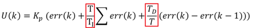
Using ki and kd instead of integral is the most commonly used formula below (this is the commonly used positional pid version)

Then we modify another version, as shown below (this is called incremental pid)

It can be seen that this method only counts the current error and the last error, and the above position formula counts all the error items since the beginning. After the above position formula version is output, it is directly used as the output value of the controller, while the incremental formula is superimposed into the output of the controller as the increment.
3. Sensor data acquisition
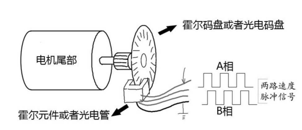
Hall code disk structure diagram:
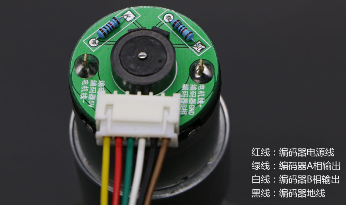
The coding on the motor is as follows:
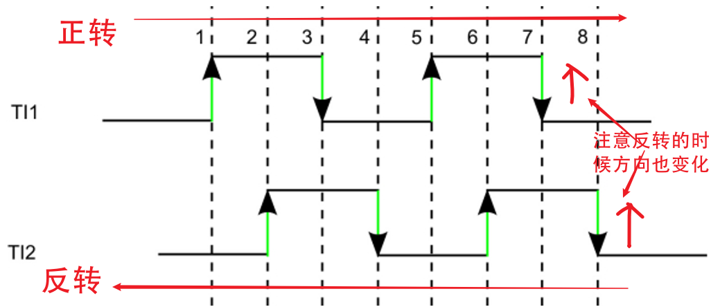
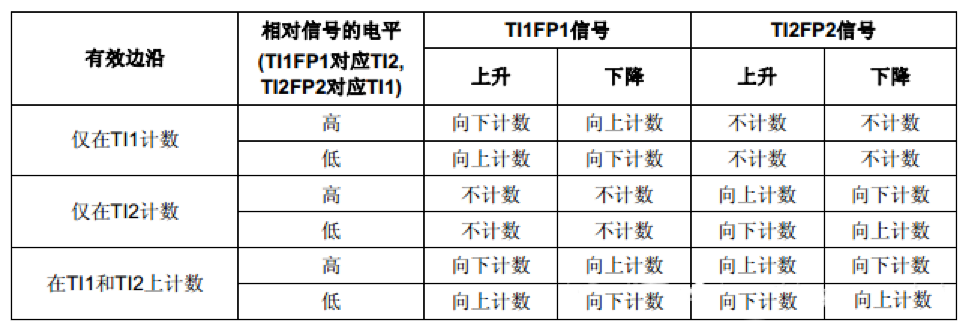
How to read data? Look at the following, one chart and one table, corresponding to reading
Note here: stm32 uses the hardware encoder mode. The reading process is automatic. Just configure the encoder mode, but other functions without the hardware encoder mode need to be simulated and implemented in software. How to simulate - just use gpio interrupt and if condition to interpret according to the following table.
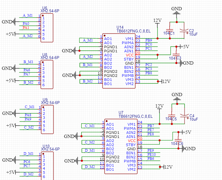
4. The hardware adopted is as follows (already in the open source of Lichuang)
In fact, there are no hardware requirements. I drew a board just for ease of use. The board interface is directly compatible with the coding motor. I have tried several models on the market. There is basically no need to change the line. It can be used directly by plugging in.
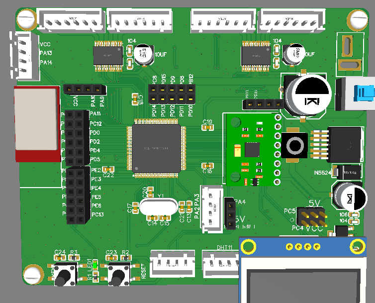 Pay attention to the interface of the motor part. After all, this is a little useful
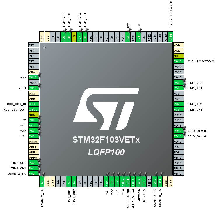
5. Project configuration
Some may be useless. It mainly depends on the motor pwm interface, encoder capture interface and motor direction interface
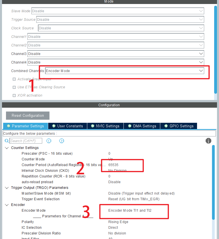
Timer 8 1 3 2 adopts encoder mode, and the configuration is as follows
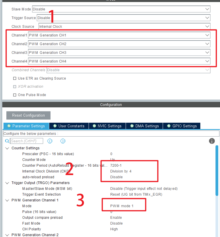
pwm setting. A timer here is enough. If the reload is set to 7199, the maximum pwm is 7200. That's OK
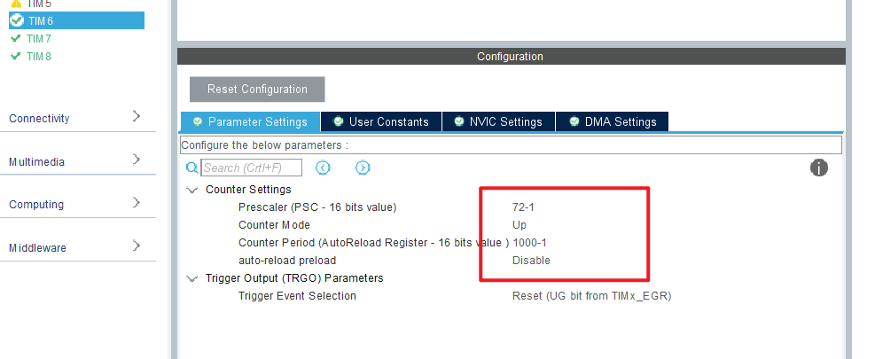
For the basic time configuration, I didn't use the writing method of the operating system. I directly interrupted it with a timer (it's an old project after all, and it's convenient to take it directly). Using timer 6, we can see that the timing time is once 1ms.
To sum up, the resource allocation is as follows:
| Interface type | Peripheral resources | pattern |
| Encoder port | TIM8 TIM1 TIM3 TIM2 | Encoder mode (T12) |
| Motor Interface | M11 M12 M21 M22 M31 M32 M41 M42 | Look at the schematic |
| PWM port | TIM4 (CH1 ~ 4) | Variation range 0-7200 |
| Basic timing | TIM6 | 1ms once |
6. Software program configuration
1. For motor configuration, it is convenient to package each motor into a function here, including internal letter limiting, motor commutation and PWM setting. Wall crack is recommended hhh
void AAC_MotorFL_Run(int16_t speed)
{
	if(speed > 0)  	{GPIOE->BRR = m11_Pin;GPIOE->BSRR = m12_Pin;}
	else            {speed = -speed;GPIOE->BSRR = m11_Pin;GPIOE->BRR = m12_Pin;}
	if(speed > 7100) speed = 7100;
	__HAL_TIM_SetCompare(&htim4,TIM_CHANNEL_1,speed);
}
void AAC_MotorFR_Run(int16_t speed)
{
	if(speed > 0)  	{GPIOE->BRR = m21_Pin;GPIOE->BSRR = m22_Pin;}
	else            {speed = -speed;GPIOE->BSRR = m21_Pin;GPIOE->BRR = m22_Pin;}
	if(speed > 7100) speed = 7100;
	__HAL_TIM_SetCompare(&htim4,TIM_CHANNEL_2,speed);
}
void AAC_MotorBL_Run(int16_t speed)
{
	if(speed > 0)  	{GPIOC->BRR = m31_Pin;GPIOC->BSRR = m32_Pin;}
	else            {speed = -speed;GPIOC->BSRR = m31_Pin;GPIOC->BRR = m32_Pin;}
	if(speed > 7100) speed = 7100;
	__HAL_TIM_SetCompare(&htim4,TIM_CHANNEL_3,speed);
}
void AAC_MotorBR_Run(int16_t speed)
{
	if(speed > 0)  	{GPIOC->BRR = m41_Pin;GPIOC->BSRR = m42_Pin;}
	else            {speed = -speed;GPIOC->BSRR = m41_Pin;GPIOC->BRR = m42_Pin;}
	if(speed > 7100) speed = 7100;
	__HAL_TIM_SetCompare(&htim4,TIM_CHANNEL_4,speed);
}
2. Encoder speed measurement. The encoder mode of the timer is a special counting mode, and the measured value is still stored in cnt. Therefore, as long as the value of cnt is read, the current count value of the encoder can be obtained.
int Read_Encoder(uint8_t TIMX)
{
int Encoder_TIM;
switch(TIMX)
{
case 2: Encoder_TIM = (short)TIM2 -> CNT; TIM2 -> CNT=0;break;
case 3: Encoder_TIM = (short)TIM3 -> CNT; TIM3 -> CNT=0;break;
case 1: Encoder_TIM = (short)TIM1 -> CNT; TIM1 -> CNT=0;break;
case 8: Encoder_TIM = (short)TIM8 -> CNT; TIM8 -> CNT=0;break;
default: Encoder_TIM = 0;
}
return Encoder_TIM;
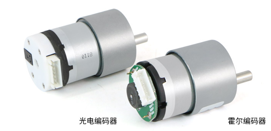
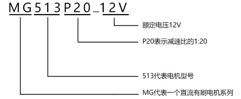
}3. There are two kinds of encoding motors commonly used in the market, which are composed of motor + reducer + encoder. The motor is the innermost main body, the front sleeve is the reducer, and the tail is the encoder. The captured value is determined by the encoder and reducer.
The reduction ratio can be obtained from the sticker or model on the motor. For example, 10F is pasted, which means that the reduction ratio is 10:1
The encoder harness of common hall encoder and photoelectric encoder is described below
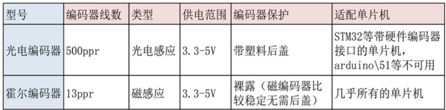
It can be seen that the number of lines of the power off encoder is much larger than that of the hall encoder, which makes the photoelectric encoder more suitable for high-precision applications. Then the final formula is
One revolution of driving shaft = reduction ratio * number of encoder lines
4. The timer creates a task cycle. Previously, a timer interrupt once every 1ms has been created. Here, the judgment is added to the interrupt service function. Here, according to experience, the judgment is as follows (why? The value obtained in this way is reasonable, and the maximum speed is more than 100 when pwm is fully loaded):
- Photoelectric encoder: read data once in 2ms
- Hall encoder: read data once in 10ms
//Timer task cycle
void HAL_TIM_PeriodElapsedCallback(TIM_HandleTypeDef *htim)
{
  static int time;
  if(htim->Instance == htim6.Instance)
  {
		if(time % 10 == 0)
		{
            //Once every 10ms
		}
		if(time >= 1000)
		{
			time = 0;
			HAL_GPIO_TogglePin(GPIOD, led_Pin);
		}
  }
}
5. pid formula
- This is directly restored according to the discrete formula
typedef struct
{
	float Kp, Ki, Kd;
	float P, I, D;
	float Error_Last;
}PositionPID_t;
// pid calculation
int Position_PID( PositionPID_t *pid, float set_value, float now_value )
{
	pid->P = set_value - now_value;
	pid->I += pid->P;
	pid->D = pid->P - pid->Error_Last;
	pid->Error_Last = pid->P;
	pid->I=pid->I>10000?10000:(pid->I<(-10000)?(-10000):pid->I);
	if( set_value == 0 )			pid->I = 0;

	return( pid->Kp*pid->P  +  pid->Ki*pid->I  +  pid->Kd*pid->D );
}- From the balance car house
//Position PID controller
int Position_PI (int Encoder, int Target)
{
  //   float Kp=0.02,Ki=0.0002;
  static int Bias, Pwm;
  static long Integral_bias;
  Bias = Encoder - Target;            //Calculation deviation
  Integral_bias += Bias;	             //Find the integral of the deviation
  if(Integral_bias > 1500000)  Integral_bias = 1500000; //Integral limiting
  if(Integral_bias < -1500000)  Integral_bias = -1500000; //Integral limiting
  Pwm = Position_Kp * Bias + Position_Ki * Integral_bias; //Position PI controller
  return Pwm;                         //Incremental output
}
//Incremental PI controller
int Incremental_PI (int Encoder, int Target)
{
  //   float Kp=20,Ki=30;
  static int Bias, Pwm, Last_bias;
  Bias = Encoder - Target;            //Calculation deviation
  Pwm += Incremental_Kp * (Bias - Last_bias) + Incremental_Ki * Bias; //Incremental PI controller
  Last_bias = Bias;	                 //Save last deviation
  return Pwm;                         //Incremental output
}- Dajiang robomaster official routine
pid.c
#include "pid.h"
#include "main.h"

#define LimitMax(input, max)   \
    {                          \
        if (input > max)       \
        {                      \
            input = max;       \
        }                      \
        else if (input < -max) \
        {                      \
            input = -max;      \
        }                      \
    }

void PID_init(pid_type_def *pid, uint8_t mode, const fp32 PID[3], fp32 max_out, fp32 max_iout)
{
  if (pid == NULL || PID == NULL)
  {
    return;
  }
  pid->mode = mode;
  pid->Kp = PID[0];
  pid->Ki = PID[1];
  pid->Kd = PID[2];
  pid->max_out = max_out;
  pid->max_iout = max_iout;
  pid->Dbuf[0] = pid->Dbuf[1] = pid->Dbuf[2] = 0.0f;
  pid->error[0] = pid->error[1] = pid->error[2] = pid->Pout = pid->Iout = pid->Dout = pid->out = 0.0f;
}

fp32 PID_calc(pid_type_def *pid, fp32 ref, fp32 set)
{
  if (pid == NULL)
  {
    return 0.0f;
  }
  pid->error[2] = pid->error[1];
  pid->error[1] = pid->error[0];
  pid->set = set;
  pid->fdb = ref;
  pid->error[0] = set - ref;
  if (pid->mode == PID_POSITION)
  {
    pid->Pout = pid->Kp * pid->error[0];
    pid->Iout += pid->Ki * pid->error[0];
    pid->Dbuf[2] = pid->Dbuf[1];
    pid->Dbuf[1] = pid->Dbuf[0];
    pid->Dbuf[0] = (pid->error[0] - pid->error[1]);
    pid->Dout = pid->Kd * pid->Dbuf[0];
    LimitMax(pid->Iout, pid->max_iout);
    pid->out = pid->Pout + pid->Iout + pid->Dout;
    LimitMax(pid->out, pid->max_out);
  }
  else if (pid->mode == PID_DELTA)
  {
    pid->Pout = pid->Kp * (pid->error[0] - pid->error[1]);
    pid->Iout = pid->Ki * pid->error[0];
    pid->Dbuf[2] = pid->Dbuf[1];
    pid->Dbuf[1] = pid->Dbuf[0];
    pid->Dbuf[0] = (pid->error[0] - 2.0f * pid->error[1] + pid->error[2]);
    pid->Dout = pid->Kd * pid->Dbuf[0];
    pid->out += pid->Pout + pid->Iout + pid->Dout;
    LimitMax(pid->out, pid->max_out);
  }
  return pid->out;
}

void PID_clear(pid_type_def *pid)
{
  if (pid == NULL)
  {
    return;
  }
  pid->error[0] = pid->error[1] = pid->error[2] = 0.0f;
  pid->Dbuf[0] = pid->Dbuf[1] = pid->Dbuf[2] = 0.0f;
  pid->out = pid->Pout = pid->Iout = pid->Dout = 0.0f;
  pid->fdb = pid->set = 0.0f;
}
pid.h
#ifndef PID_H
#define PID_H
#include "struct_typedef.h"
enum PID_MODE
{
  PID_POSITION = 0,
  PID_DELTA
};

typedef struct
{
  uint8_t mode;
  //PID three parameters
  fp32 Kp;
  fp32 Ki;
  fp32 Kd;

  fp32 max_out;  //maximum output
  fp32 max_iout; //Maximum integral output

  fp32 set;
  fp32 fdb;

  fp32 out;
  fp32 Pout;
  fp32 Iout;
  fp32 Dout;
  fp32 Dbuf[3];  //Differential term 0 latest 1 last 2 last
  fp32 error[3]; //Error item 0 latest 1 last 2 last

} pid_type_def;

extern void PID_init(pid_type_def *pid, uint8_t mode, const fp32 PID[3], fp32 max_out, fp32 max_iout);
extern fp32 PID_calc(pid_type_def *pid, fp32 ref, fp32 set);
extern void PID_clear(pid_type_def *pid);

#endif
The example written by Dajiang official is more intuitive, has the feeling of object-oriented, and is comfortable to use, but it is also a direct set of formulas without adding some methods to optimize pid. I will use the perfect version in the next version.
7. Parameter adjustment process record
Let's put the classic diagram first, and see the function of parameters
Speed single loop: the codes in the cycle are as follows
			enc = Read_Encoder(8);
			pwm = PID_calc(&motor_speed_pid,enc,target);//Velocity loop
			AAC_MotorFL_Run(pwm);
Position single ring: the code in the cycle is as follows
			enc += Read_Encoder(8);
			pwm = PID_calc(&motor_angle_pid,enc,target);//Position ring
			AAC_MotorFL_Run(pwm);
Position speed double loop: the code in the cycle is as follows
			enc += Read_Encoder(8);
			pwm = PID_calc(&motor_angle_pid,enc,target);//Position ring
			pwm = PID_calc(&motor_speed_pid,Read_Encoder(8),pwm);//Velocity loop
			AAC_MotorFL_Run(pwm);
The angle control effect is not adjusted very well. It will be hhh improved next time
Note: for angle control, in fact, the use of position ring alone has had a certain effect, but it is not effective or stable. Therefore, it is recommended to use double closed loop, and the angle can only be used as a parameter adjustment exercise.
I have uploaded the source code to csdn. The link is as follows
DC coded motor speed position double closed loop - manufacturing document resources - CSDN Library