preface
opencv part about image drawing
1, Draw graphics
Opencv4 provides the circle () function for drawing graphics
Drawing a circle: prototype of the circle() function
void circle(InputOutputArray img, Point center, int radius, const Scalar & color, int thickness = 1, int lineType = LINE_8, int shift = 0)
img: need to draw a circular image
Center: coordinates of the center of the circle
Radius: the radius of a circle, in pixels
Color: the color of the circle
thickness: the width of the contour. If the value is negative, a solid circle is drawn
lineType: the type of boundary, which can be FILLED or LINE_4,LINE_8 and LINE_A4
shift: the number of decimal places in the center coordinate and radius value
This function is used to draw a circular pattern in an image. The input parameters are the center position and radius of the circle, as well as the width and linetype of the boundary line.
Draw a line: prototype of line() function
void line(InputOutputArray img, Point pt1, Point pt2, const Scalar & color, int thickness = 1, int lineType = LINE_8, int shift = 0)
pt1: coordinates of the starting point of the line in the image
pt2: coordinates of the line end point in the image
Color: the color of a straight line, represented by three channels
Draw ellipse: prototype of ellipse() function
void ellipse(InputOutputArray img, Point center, Size axes, double angle, double startAngle, double endAngle, const Scalar & color, int thickness = 1, int lineType = LINE_8, int shift)
Center: the center coordinate of the ellipse
axes: half the size of the ellipse's principal axis
Angle: the rotation angle of the ellipse, in degrees
startAngle: the starting angle of the elliptical arc, in degrees
endAngle: the angle at which the elliptical arc ends, in degrees
This function uniquely determines an ellipse by selecting the center position of the ellipse and the size of the main axis, and can control the rotation angle to change the position of the ellipse in the coordinate system. Through the starting and ending angles of elliptical arc, you can draw a complete ellipse or part of an arc. When the thickness of the boundary line is negative, a solid ellipse will be drawn.
Draw rectangle: prototype of rectangle() function
void rectangle(InputOutputArray img, Point pt1, Point pt2, const Scalar & color, int thickness = 1, int lineType = LINE_8, int shift = 0)
void rectangle(InputOutputArray img, Rect rec, const Scalar & color, int thickness = 1, int lineType = LINE_8, int shift = 0)
pt1: one vertex of the rectangle
pt2: the vertex opposite to pt1 in the rectangle, that is, the two points are on the diagonal
rec: top left corner vertex and width of rectangle
The method of drawing a solid rectangle is the same as the above. Rect represents the pixel coordinates of the upper left corner of the rectangle, as well as the length and width of the rectangle. The format defined by this type is Rect (pixel x coordinate, pixel y coordinate, rectangle width and rectangle height). The data types that can be stored are int type (Rect2i or rect), double type (Rect2d) and float type (Rect2f)
Drawing polygons: prototype of fillPoly() function
void fillPoly(InputOutputArray img, const Point ** pts, const int * npts, int ncontours, const Scalar & color, int lineType = LINE_8, int shift = 0, Point offset = Point())
pts: polygon vertex array, which can store the vertex coordinates of multiple polygons
npts: number of vertices in each polygon vertex array
ncontours: the number of polygons drawn
Offset: optional offset of all vertices
The vertices of the polygon need to be given clockwise or counterclockwise. Whether to draw a solid polygon can be achieved by controlling the width of the boundary line.
Text generation: putText() function prototype
void putText(InputOutputArray img, const String & text, Point org, int fontFace, double fontScale, Scalar color, int thickness = 1, int lintType = LINE_8, bool bottomLeftOrigin = false)
Text: text output to image
org: the pixel coordinate of the lower left corner of the Chinese character string of the image
fontFace: selection flag of font type
bottomLeftOrigin: the position of the image data origin. The default is the upper left corner. If the parameter is changed to true, the default is the lower left corner
Sample program:
#include<opencv2\opencv. HPP > / / load the header file of OpenCV4
#include<iostream>
#include<vector>
using namespace std;
using namespace cv; //OpenCV namespace
int main()
{
Mat img = img.zeros(Size(512,512),CV_8UC3); //Generates a black image for drawing geometry
//Draw circle
circle(img, Point(50, 50), 25, Scalar(255, 255, 255),-1); //Draw a solid circle in solid white
circle(img, Point(100, 50), 20, Scalar(255, 255, 255), 4); //Draw a hollow circle
//draw a straight line
line(img, Point(100, 100), Point(200, 100), Scalar(255, 255, 255), 2,LINE_4, 0);
//Draw ellipse
ellipse(img, Point(300, 255), Size(100, 70), 0, 0, 100, Scalar(255, 255, 255),-1);
ellipse(img, RotatedRect(Point2f(150, 100), Size2f(30, 20), 0), Scalar(0, 0, 255), 2);
vector<Point> points;
//Use some points to approximate an ellipse
ellipse2Poly(Point(200, 400), Size(100, 70), 0, 0, 360, 2, points);
for (int i = 0; i < points.size() - 1; i++)
{
if (i == points.size() - 1)
{
//The last point of the ellipse connects with the first point
line(img, points[0], points[i], Scalar(255, 255, 255), 2);
break;
}
//The current point is connected to the next point
line(img, points[i], points[i + 1], Scalar(255, 255, 255), 2);
}
//draw rectangle
rectangle(img, Point(50, 400), Point(100, 450), Scalar(125, 125, 125), -1);
rectangle(img, Rect(400, 450, 60, 50), Scalar(0, 125, 125), 2);
//draw a polygon
Point pp[2][6];
pp[0][0] = Point(72, 200);
pp[0][1] = Point(142, 204);
pp[0][2] = Point(226, 263);
pp[0][3] = Point(172, 310);
pp[0][4] = Point(117, 319);
pp[0][5] = Point(15, 260);
pp[1][0] = Point(359, 339);
pp[1][1] = Point(447, 351);
pp[1][2] = Point(504, 349);
pp[1][3] = Point(484, 433);
pp[1][4] = Point(418, 449);
pp[1][5] = Point(354, 402);
Point pp2[5];
pp2[0] = Point(350, 83);
pp2[1] = Point(463, 90);
pp2[2] = Point(500, 171);
pp2[3] = Point(421, 194);
pp2[4] = Point(338, 141);
const Point* pts[3] = { pp[0],pp[1],pp2 }; //Generation of pts variables
int npts[] = { 6,6,5 }; //Generation of vertex number array
fillPoly(img, pts, npts, 3, Scalar(125, 125, 125), 8); //Draw 3 polygons
//Generate text
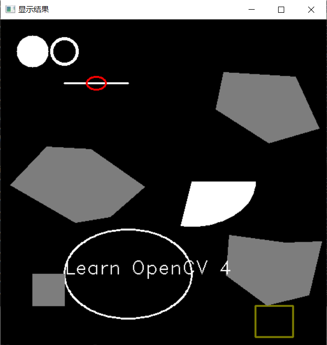
putText(img, "Learn OpenCV 4", Point(100, 400), 2, 1, Scalar(255, 255, 255));
imshow("Display results", img);
waitKey(0);
return 0; //Program end
}
Thanks for reading! You are also welcome to pay attention to Xiaobai blogger and give more encouragement!