Reading DS18B20 temperature sensor and programming
For the novice, DS18B20 basic concept is only to understand. The most important thing is to program DS18B20 with single-chip microcomputer, read the temperature information, and display the temperature information with digital tube, LCD1602 or upper computer
Get to know DS18B20
DS18B20 is a commonly used digital temperature sensor. Its output is digital signal. It has the characteristics of small volume, low hardware cost, strong anti-interference ability and high precision. [1] DS18B20 digital temperature sensor is convenient for wiring, and can be used in many occasions after being packaged, such as pipeline type, screw type, magnet adsorption type, stainless steel package type, with various models, such as LTM8877, LTM8874, etc.
Applicable scenario
The product is suitable for temperature measurement and control fields such as freezer, granary, storage tank, telecommunication room, power room, cable trough, etc. Temperature measurement and control of industrial equipment in narrow space such as bearing bush, cylinder block, spinning machine, air conditioner, etc.
Automobile air conditioning, refrigerator, freezer, and medium and low temperature drying oven, etc.
Heat metering of heating / cooling pipeline, household heat metering of central air conditioning and temperature measurement and control in industrial field.
Characteristic
1.1. The voltage range is wider, 3.0-5.5V, which can be powered by data line under parasitic power supply mode
1.2. Unique single line interface mode, when DS18B20 is connected with microprocessor, only one interface line is needed to realize bidirectional communication between microprocessor and DS18B20
1.3. DS18B20 supports multi-point networking function. Multiple DS18B20 can be connected in parallel on the only three lines to realize multi-point temperature measurement in networking
1.4. DS18B20 does not need any peripheral elements in use. All sensing elements and conversion circuits are integrated in an integrated circuit shaped like a triode
1.5. The temperature range is - 55 ℃ ~ + 125 ℃, and the accuracy is ± 0.5 ℃ at - 10 ~ + 85 ℃
1.6. The programmable resolution is 9-12 bits, and the corresponding resolvable temperature is 0.5 ℃, 0.25 ℃, 0.125 ℃ and 0.0625 ℃, respectively, which can realize high-precision temperature measurement
1.7. At 9-bit resolution, the temperature can be converted to a number within 93.75ms at most, and at 12-bit resolution, the temperature can be converted to a number within 750ms at most, which is faster
1.8. The measurement result directly outputs the digital temperature signal, which is serially transmitted to the CPU by "one line bus", and at the same time can transmit the CRC check code, which has a strong anti-interference and error correction ability
1.9 negative pressure characteristic: when the polarity of power supply is reversed, the chip will not burn due to heating, but it cannot work normally.
DS18B20 pin definition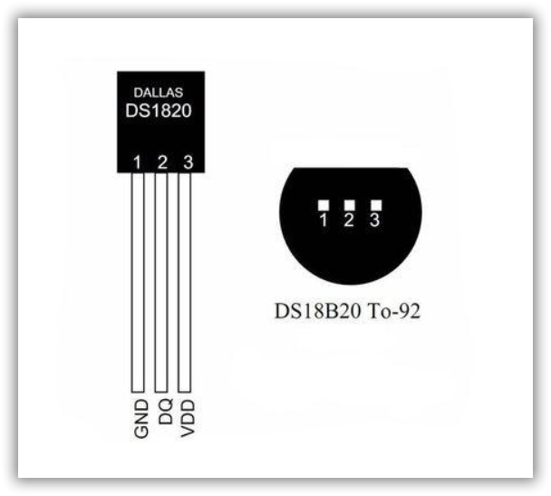
It can be seen from the figure that DS18B20 has three pins, among which GND is grounded, VCC is connected to the power supply, DQ is connected to an I/O of the single-chip microcomputer, so DS18B20 adopts the single bus mode, only one wire is needed to connect to the I/O port of the single-chip microcomputer
DS18B20 has its own A/D conversion chip, so we only need to wake up DS18B20 through 51 single chip microcomputer, set the working state of DS18B20, and read out the temperature value from the register of DS18B20. We should pay attention to the storage of negative temperature in the form of complement, and carry out the conversion of code value after reading
Code
We need to build four functions
- Function to write a byte to DS18B20
- Function to read a byte from DS18B20
- DS18B20 initialization function
- The function of reading temperature from DS18B20 register, which needs to call 2 function, that is, communication bridge
1,2 function is the bridge of communication between SCM and DS18B20 through I/0 port. It is necessary to wake up DS18B20, find the address of DS18B20, or read the temperature value after A/D conversion from the register of DS18B20. The bridge is the rule of communication, that is, the timing chart of DS18B20 device. The timing chart can be found in the chip Manual of DS18B20
But for novices, they may not understand the operation of timing, but don't be discouraged, because someone has written the function corresponding to timing, we just need to borrow it, that is to say, don't make wheels repeatedly
Programming example
It should be noted that the delay function needs to be written in combination with the crystal oscillator of the single-chip microcomputer. delay(10us) represents 10 microseconds of delay, and delay(10Ms) represents 10 microseconds of delay
#include<reg52.h>
#include<stdio.h>
#define uchar unsigned char
sbit DQ=P1^0;                         //Define DS18B20 port
void WriteOneChar(uchar dat);        //Function of single chip microcomputer writing a byte of data to DS18B20
uchar ReadOneChar(void);            //Function of single chip microcomputer reading a byte of data from DS18B20
bit Init_DS18B20(void);            //DS18B20 initialization function
uint ReadTemperature(void);       //Reading temperature function from DS18B20


**D18B20 Write a byte function**
void WriteOneChar(uchar dat)
{
uchar i=0;
for (i=8; i>0; i--)
{
  DQ = 0;
  DQ = dat&0x01;
  Delay(50us);
  DQ = 1;
  dat>>=1;
}
Delay(50us);
}


**DS18B20 Read a byte function**
uchar ReadOneChar()
{
uchar i=0;
uchar dat = 0;
for (i=8;i>0;i--)
{
  DQ = 0; // Give a pulse signal
  dat>>=1;
  DQ = 1; // Give a pulse signal
  if(DQ)
   dat|=0x80;
  Delay(50us);
}
return(dat);
}


**DS18B20 Initialization function**
bit Init_DS18B20(void)
{
bit dat=0;
DQ = 1;    			     //DQ reset
Delay(10us);  	 	    //Delay slightly
DQ = 0;      		   //Single chip microcomputer pulls DQ down
Delay(800us); 		  //Accurate delay greater than 480us and less than 960us
DQ = 1;       		 //Pull up bus
Delay(100us); 		//Receive the presence pulse of 60-240us after 15-60us
dat=DQ;            //If x=0, initialization succeeds, if x=1, initialization fails
Delay(50us);      //Slightly delayed return
return dat;
}


**DS18B20 Read temperature function**
uint ReadTemperature()
{
uchar a=0;
uint b=0;
uint t=0;
Init_DS18B20();
WriteOneChar(0xCC);  // Skip reading sequence number column number
WriteOneChar(0x44); // Start temperature conversion
Delay(10MS);
Init_DS18B20();
WriteOneChar(0xCC);  //Skip reading sequence number column number
WriteOneChar(0xBE); //Read temperature registers (9 registers in total). The first two are temperature
a=ReadOneChar();   //Low position
b=ReadOneChar();  //High position


b<<=8;
t=a+b;


return(t);//**Return the temperature value read**
}


**Timer initialization function**
//Timer is used to control the time interval of reading DS18B20 temperature
void Init_Timer0(void)
{
 TMOD = 0x01;	  //Using mode 1, 16 bit timer

 EA=1;            //Total interrupt on
 ET0=1;           //Timer interrupt on
 TR0=1;           //Timer switch on
}


**Timer interrupt function**
void Timer0_isr(void) interrupt 1
{
 static unsigned int num;
 TH0=(65536-2000)/256;		  //Reassign 2ms
 TL0=(65536-2000)%256;

 num++;
 if(num==30)        //The statement control interval can be determined by sorting the if condition
   {
    num=0;
    ReadTempFlag=1; //Read flag position 1
	}

}


char displaytemp[10]; //This array holds the temperature value read
bit  ReadTempFlag;   //Define a flag to read DS18B20 temperature
float temperature;  //Define temperature value


void main()
{
int temp;
if(ReadTempFlag==1)
			 {
				ReadTempFlag=0;
				temp=ReadTemperature();
			    temperature=(float)temp*0.0625;//The temperature value finally read can be put into an array for LCD1602 or nixie tube display
				sprintf(displaytemp,"%6.2f",temperature);//sprintf function in < stdio. H > header file
			}

