1, Light up the first LED experiment
1.F28335 GPIO introduction
1.1 GPIO concept
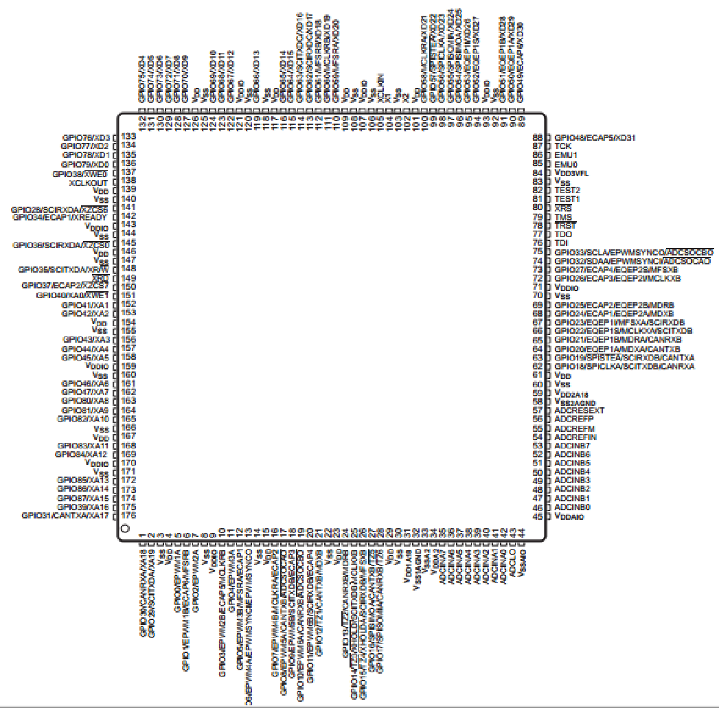
GPIO (general purpose input output) is the abbreviation of general input and output port. Its input and output can be controlled by software. (the DSP model used on the development board is TMS320F28335, and this chip has 176 pins in total)
(1) Power pin
(2) Crystal oscillator pin
(3) Reset pin
(4) Download pin
(5) BOOT pin
(6) GPIO pin
1.2 GPIO structure block diagram
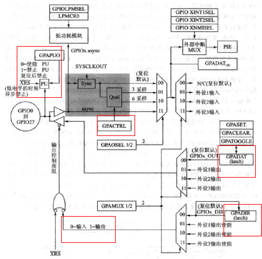
GPIO output settings:
void LED_Init(void)
{
	EALLOW;//Turn off write protection
	SysCtrlRegs.PCLKCR3.bit.GPIOINENCLK = 1;    // Turn on GPIO clock

	//LED1 port configuration
	GpioCtrlRegs.GPCMUX1.bit.GPIO68=0;//Set to general GPIO function 0 - general output 1 - peripheral 1 output 2 - peripheral 2 output 3 - peripheral 3 output
	GpioCtrlRegs.GPCDIR.bit.GPIO68=1;//Set the GPIO direction to output 1-output 0-input
	GpioCtrlRegs.GPCPUD.bit.GPIO68=0;//Enable GPIO pull-up resistor 0 - enable pull-up 1 - prohibit pull-up

	GpioDataRegs.GPCSET.bit.GPIO68=1;//Set GPIO output high level
    //GpioDataRegs.GPCCLEAR.bit.GPIO68 = 1; // Set GPIO output to low level

	EDIS;//Turn on write protection
}
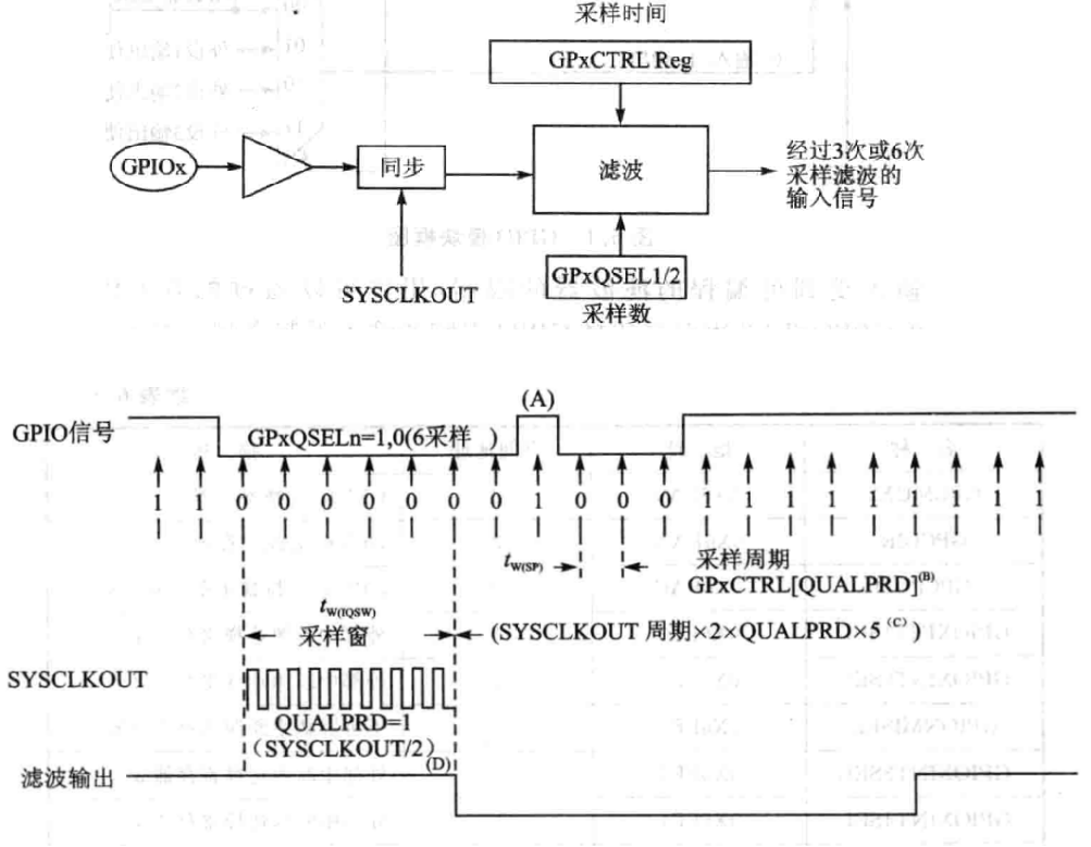
GPIO input settings:
When DSP GPIO is used as input, the hardware has its own filtering function, and the specified register is set to achieve 3 or 6 sampling filtering
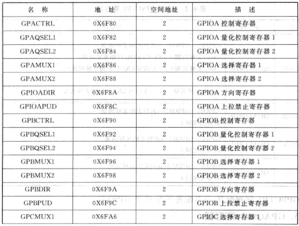
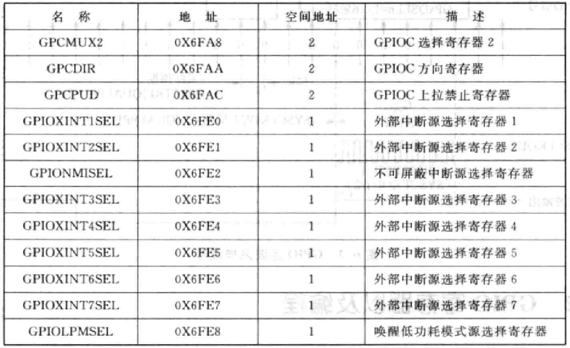
1.3 GPIO related registers
2. hardware design 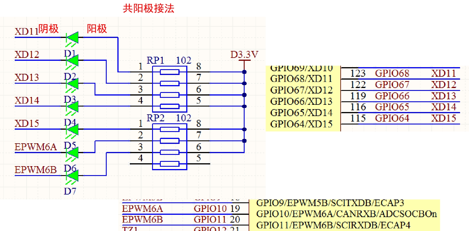
II. Buzzer experiment
Buzzer is an electronic buzzer with integrated structure, which is powered by DC voltage. It is widely used as a sound device in electronic products such as computers, printers, copiers, alarms, electronic toys, automotive electronic equipment, telephones, timers and so on. Buzzers are mainly divided into piezoelectric buzzers and electromagnetic buzzers. Piezoelectric buzzer is mainly composed of multivibrator, piezoelectric buzzer, impedance matcher, resonance box, shell, etc. The multivibrator is composed of transistors or integrated circuits. When the power is turned on (1.5~15V DC working voltage), the multivibrator vibrates and outputs an audio signal of 1.5 ~ 5kHZ. The impedance matcher pushes the piezoelectric buzzer to sound. (passive buzzer, because there is no oscillator, the volume is large, and the circuit board cannot be seen at the bottom)
The electromagnetic buzzer is composed of oscillator, electromagnetic coil, magnet, vibrating diaphragm and shell. After the power is turned on, the audio signal current generated by the oscillator passes through the electromagnetic coil to make the electromagnetic coil generate a magnetic field, and the vibrating diaphragm vibrates and sounds periodically under the interaction of the electromagnetic coil and the magnet. (active buzzer, small size, circuit board visible at the bottom)
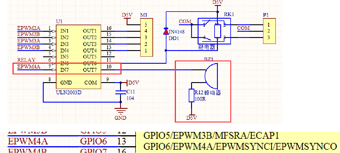
When the buzzer is driven, a driving chip needs to be added. The driving current of GPIO port cannot reach the working current of the buzzer. The figure shows a passive buzzer, which needs to output pulses to work
#define BEEP_ON			(GpioDataRegs.GPASET.bit.GPIO6=1)
#define BEEP_OFF		(GpioDataRegs.GPACLEAR.bit.GPIO6=1)
#define BEEP_TOGGLE 		 (GpioDataRegs.GPATOGGLE.bit.GPIO6=1) / / semicolon cannot be added

void BEEP1_Init(void)
{
	EALLOW;
	SysCtrlRegs.PCLKCR3.bit.GPIOINENCLK = 1;// Turn on GPIO clock
	//BEEP port configuration
	GpioCtrlRegs.GPAMUX1.bit.GPIO6=0;
	GpioCtrlRegs.GPADIR.bit.GPIO6=1;
	GpioCtrlRegs.GPAPUD.bit.GPIO6=0;

	GpioDataRegs.GPACLEAR.bit.GPIO6=1;
	EDIS;
}

void main()
{
	int i = 0;
	InitSysCtrl();//The system clock is initialized. All peripheral clocks of F28335 are turned on by default

	LED1_Init();
	BEEP1_Init();

	while(1)
	{
		i++;

		BEEP_TOGGLE;    //GPIO flip

		if(i%1000==0)
		{
			LED1_TOGGLE;
		}
		DELAY_US(100);    //The delay can make the output pulse of GPIO port drive the buzzer to work
	}

}
3, Key control experiment
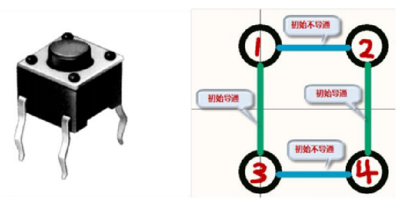
1. Key introduction
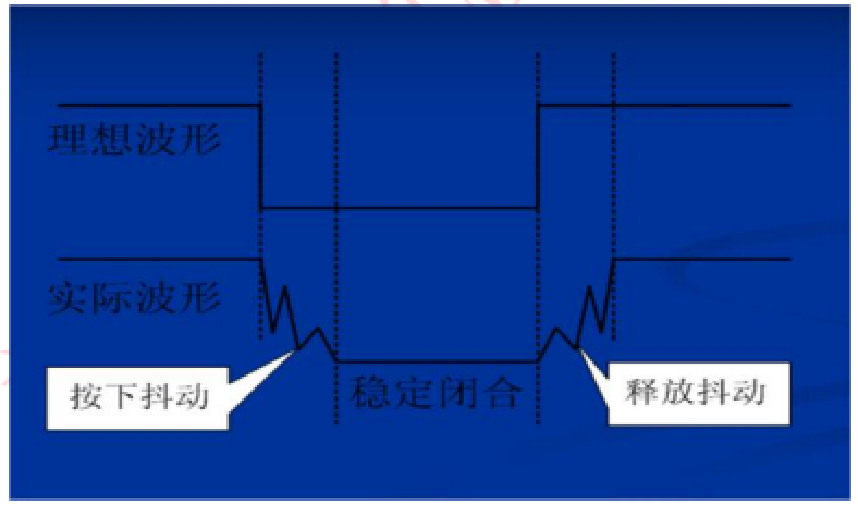
The key is an electronic switch. When in use, the switch can be turned on by gently pressing the switch button. When the hand is released, the switch will be turned off.
1.1 matrix keyboard introduction
There are many kinds of matrix keyboard detection methods, the most commonly used are row column scanning and line reversal. When detecting by row column scanning method, first send one column as low level, and the other columns are all high level (at this time, we determine the number of columns), and then immediately detect whether each row has low level in turn. If a low level of a behavior is detected (at this time, we determine the number of rows), we can confirm which row and column of the currently pressed key is, In the same way, send each column a low level in turn, and then detect whether each row becomes a low level in turn. In this way, all keys can be detected. When a key is pressed, which key is pressed can be determined. Of course, we can also set the row line to low level and scan whether the column has low level. So as to achieve the detection of the whole keyboard.
Line reversal method is to make all line lines at low level, detect whether all column lines have low level, and if so, record the column line value; Then turn it over to make all column lines low level, detect the values of all row lines, and the values of row lines will also change due to the pressing of the key, and record the values of row lines. Thus, all keys can be detected.
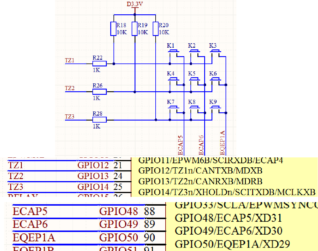
2. Hardware design
3. software design
#define KEY_L1_SetL			(GpioDataRegs.GPBCLEAR.bit.GPIO48=1)
#define KEY_L2_SetL			(GpioDataRegs.GPBCLEAR.bit.GPIO49=1)
#define KEY_L3_SetL			(GpioDataRegs.GPBCLEAR.bit.GPIO50=1)

#define KEY_L1_SetH			(GpioDataRegs.GPBSET.bit.GPIO48=1)
#define KEY_L2_SetH			(GpioDataRegs.GPBSET.bit.GPIO49=1)
#define KEY_L3_SetH			(GpioDataRegs.GPBSET.bit.GPIO50=1)

#define KEY_H1			(GpioDataRegs.GPADAT.bit.GPIO12)
#define KEY_H2			(GpioDataRegs.GPADAT.bit.GPIO13)
#define KEY_H3			(GpioDataRegs.GPADAT.bit.GPIO14)

#define KEY1_PRESS		1
#define KEY2_PRESS		2
#define KEY3_PRESS		3
#define KEY4_PRESS		4
#define KEY5_PRESS		5
#define KEY6_PRESS		6
#define KEY7_PRESS		7
#define KEY8_PRESS		8
#define KEY9_PRESS		9
#define KEY_UNPRESS		0

void KEY_Init(void)
{
	EALLOW;
	SysCtrlRegs.PCLKCR3.bit.GPIOINENCLK = 1;// Turn on GPIO clock

	//KEY port configuration
    /*GPIO Input terminal*/
	GpioCtrlRegs.GPAMUX1.bit.GPIO12=0;
	GpioCtrlRegs.GPADIR.bit.GPIO12=0;    // GPIO set as input
	GpioCtrlRegs.GPAPUD.bit.GPIO12=0;

	GpioCtrlRegs.GPAMUX1.bit.GPIO13=0;
	GpioCtrlRegs.GPADIR.bit.GPIO13=0;    // GPIO set as input
	GpioCtrlRegs.GPAPUD.bit.GPIO13=0;

	GpioCtrlRegs.GPAMUX1.bit.GPIO14=0;
	GpioCtrlRegs.GPADIR.bit.GPIO14=0;    // GPIO set as input
	GpioCtrlRegs.GPAPUD.bit.GPIO14=0;

    /*GPIO Output terminal*/
	GpioCtrlRegs.GPBMUX2.bit.GPIO48=0;
	GpioCtrlRegs.GPBDIR.bit.GPIO48=1;    // GPIO set to output
	GpioCtrlRegs.GPBPUD.bit.GPIO48=0;

	GpioCtrlRegs.GPBMUX2.bit.GPIO49=0;
	GpioCtrlRegs.GPBDIR.bit.GPIO49=1;    // GPIO set to output
	GpioCtrlRegs.GPBPUD.bit.GPIO49=0;

	GpioCtrlRegs.GPBMUX2.bit.GPIO50=0;
	GpioCtrlRegs.GPBDIR.bit.GPIO50=1;    // GPIO set to output
	GpioCtrlRegs.GPBPUD.bit.GPIO50=0;

	GpioDataRegs.GPBSET.bit.GPIO48=1;
	GpioDataRegs.GPBSET.bit.GPIO49=1;
	GpioDataRegs.GPBSET.bit.GPIO50=1;

	EDIS;
}

char KEY_Scan(char mode)    //mode=0 single scan mode=1 cyclic scan
{

	static char keyl1=1;
	static char keyl2=1;
	static char keyl3=1;

	//Column 1 scan
	KEY_L1_SetL;
	KEY_L2_SetH;
	KEY_L3_SetH;
	if(keyl1==1&&(KEY_H1==0||KEY_H2==0||KEY_H3==0))
	{
		DELAY_US(10000);    //Debounce
		keyl1=0;
		if(KEY_H1==0)
		{
			return KEY1_PRESS;
		}
		else if(KEY_H2==0)
		{
			return KEY4_PRESS;
		}
		else if(KEY_H3==0)
		{
			return KEY7_PRESS;
		}
	}
	else if(KEY_H1==1&&KEY_H2==1&&KEY_H3==1)
	{
		keyl1=1;
	}
	if(mode)
		keyl1=1;


	//Column 2 scan
	KEY_L2_SetL;
	KEY_L1_SetH;
	KEY_L3_SetH;
	if(keyl2==1&&(KEY_H1==0||KEY_H2==0||KEY_H3==0))
	{
		DELAY_US(10000);//Debounce
		keyl2=0;
		if(KEY_H1==0)
		{
			return KEY2_PRESS;
		}
		else if(KEY_H2==0)
		{
			return KEY5_PRESS;
		}
		else if(KEY_H3==0)
		{
			return KEY8_PRESS;
		}
	}
	else if(KEY_H1==1&&KEY_H2==1&&KEY_H3==1)
	{
		keyl2=1;
	}
	if(mode)
		keyl2=1;


	//Column 3 scan
	KEY_L3_SetL;
	KEY_L1_SetH;
	KEY_L2_SetH;
	if(keyl3==1&&(KEY_H1==0||KEY_H2==0||KEY_H3==0))
	{
		DELAY_US(10000);//Debounce
		keyl3=0;
		if(KEY_H1==0)
		{
			return KEY3_PRESS;
		}
		else if(KEY_H2==0)
		{
			return KEY6_PRESS;
		}
		else if(KEY_H3==0)
		{
			return KEY9_PRESS;
		}
	}
	else if(KEY_H1==1&&KEY_H2==1&&KEY_H3==1)
	{
		keyl3=1;
	}
	if(mode)
		keyl3=1;

	return KEY_UNPRESS;
}

void main()
{
	int i=0;
	char key=0;

	InitSysCtrl();

	LED_Init();
	KEY_Init();

	while(1)
	{
		key=KEY_Scan(0);
		switch(key)
		{
			case KEY1_PRESS: LED2_TOGGLE;break;
			case KEY2_PRESS: LED3_TOGGLE;break;
			case KEY3_PRESS: LED4_TOGGLE;break;
			case KEY4_PRESS: LED5_TOGGLE;break;
			case KEY5_PRESS: LED6_TOGGLE;break;
			case KEY6_PRESS: LED7_TOGGLE;break;
		}

		i++;
		if(i%2000==0)
		{
			LED1_TOGGLE;
		}
		DELAY_US(100);
	}
}