Realize the dynamic counting of the digital tube, once every 0.1 seconds
The connection modes of digital tubes are divided into common cathode digital tube and common anode digital tube.
Digital Pipe Pin: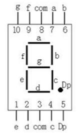
The two com pins in the figure above are actually linked together. The public end of the other pins is called bit selection. The level of bit selection determines whether the digital tube can be lighted or not. The other pins select signals for segments and decide which diode on the digital tube emits light.
Common cathode digital tube connection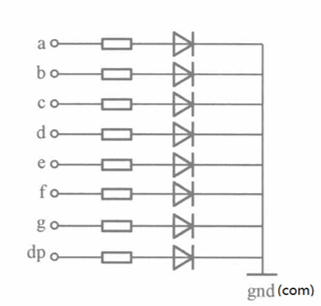
Connection mode of common anode digital tube: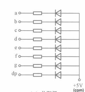
Gongyang Eight-segment Pole Digital Tube True Value Table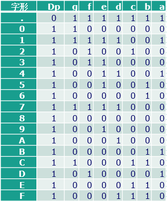
Digital tube schematic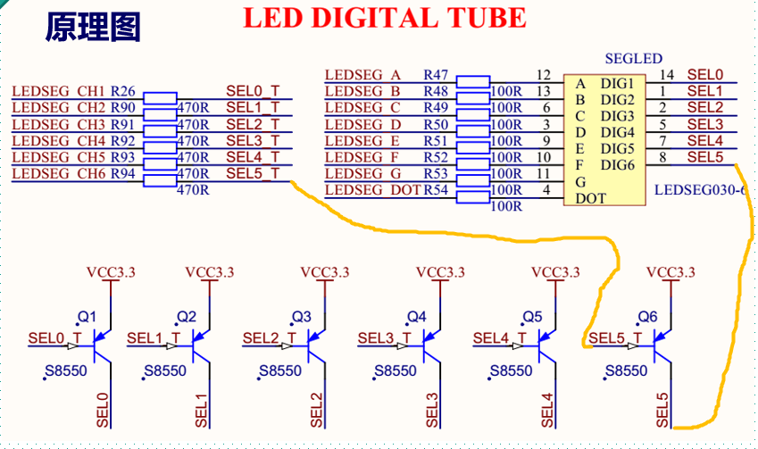
Take the fifth digital tube as an example, LED SEG CH6 is connected to the base of Q6 triode through 470R resistance, bitwise SEL5 of the fifth digital tube is connected to the collector of Q6 triode, emitter of Q6 triode, and power supply.So in the code, simply assign the LED SEG CH6 (code sense bit selection) to 0 (low level), then the real segment of the tube connects to the power supply, this digital tube bit co-anode digital tube.In the circuit diagram of the digital tube, six digital tubes share eight segment selector signals, which are connected with the LED pin.So, when the display is static, the six digital tubes display the same.
Digital tube dynamic display drive mode: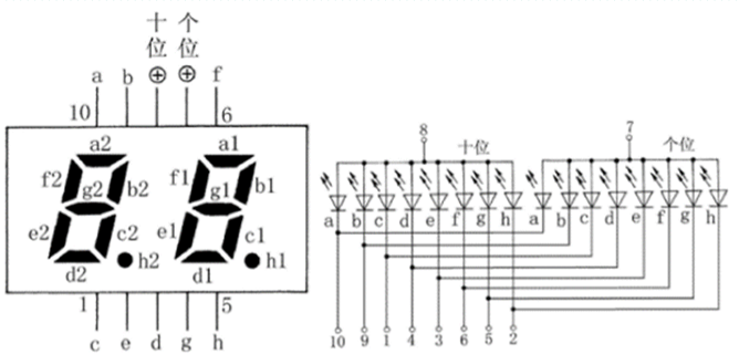
At the same time, only one digital tube can be displayed. According to the persistence effect of human vision, the time interval of the alternating display of the digital tube can be controlled. The switch time of the digital tube is fast enough, and the naked eye effect is that multiple digital tubes are illuminated at the same time.
System Diagram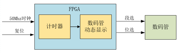
Top module schematic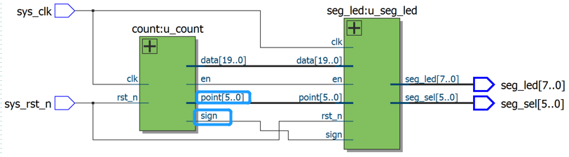
point[5:0] and sign were not used in this experiment.
Code implementation:
Top Module Design
module top_seg_led(
    input   sys_clk,//Global clock signal
    input   sys_rst_n, //Reset signal

    output [5:0] seg_sel, //Digital Pipe Position Selection Signal
    output [7:0] seg_led //Digital tube segment selection signal
);

wire define
wire    [19:0] data; //Numeric value displayed by digital tube
wire    [5:0]  point; //Position of decimal point on digital tube
wire           en; //Digital tube display enable signal
wire           sign; //Symbol bits for display data on digital tubes

//Counter module that generates the data the tube needs to display
count u_count(
    .clk    (sys_clk), //clock signal
    .rst_n  (sys_rst_n), //Reset signal

    .data   (data), //Number to display for 6-digit tube
    .point  (point),
);


//Digital tube dynamic display module
seg_led u_seg_led(
    .clk        (sys_clk), //clock signal
    .rst_n      (sys_rst_n), //Reset signal

    .data       (data), //Displayed values
    .point      (point), //Decimal specific display position, high level effective
    .en         (en), //Digital tube enabling signal
    .sign       (sign), //Symbol Bit, High Level Display Negative Sign

    .seg_sel    (seg_sel), //Bit Selection
    .sed_led    (seg_led) //Segment Selection
);
endmodule
Timing module
module count(
    input       clk, //clock signal
    input       rst_n, //Reset signal

    output reg [19:0]   data, //Six digital tubes display values, six digital tubes display 999999 max, occupy 20bit
    output reg [5:0]    point, //The position of decimal point, high level lighting corresponds to decimal point on the digital tube position. (Not used in this experiment)
    output reg          en, //Digital tube enabling signal
    output reg          sign //Symbol bit, negative sign at high level, no negative sign at low level, not used in this experiment
 );

 //parameter define
 parameter MAX_NUM = 23'd5000_000; //Maximum counter count, the tube counts every 0.01s

 //reg define
 reg [22:0] cnt; //Counter for timing 100ms(0.1s)
 reg        flag; //Sign signal

 //When the counter counts the system clock up to 10ms, it outputs a pulse signal of one clock cycle
 always @ (posedge clk or negedge rst_n) begin
    if(!rst_n) begin
        cnt <= 23'b0;
        flag <= 1'b0;
    end
    else if (cnt < MAX_NUM - 1'b1) begin
        cnt <= cnt + 1'b1;
        flag <= 1'b0;
    end
    else begin
        cnt <= 23'b0;
        flag <= 1'b1; //Output a cycle high level signal every 0.01 seconds
    end
end

//The data that the tube needs to display, from 0 to 999999
always @ (posedge clk or negedge rst_n) begin
    if(!rst_n) begin
        data <= 20'b0;
        point <= 6'b000000; //No decimal points need to be displayed, assign 0
        en <= 1'b0;
        sign <= 1'b0; //Negative sign not required, assign 0
    end
    else begin
        point <= 6'b000000;  //Do not display decimal points
        en <= 1'b1; //Turn on the digital tube enable signal
        sign <= 1'b0; //Do not show negative sign
        if (flag) begin //Display values accumulating every 0.01s
            if(data < 20'd999999)
                data <= data + 1'b1;
            else
                data <= 20'b0;
        end
   end
end

endmodule
Digital tube design module
module seg_led(
    input                   clk    ,        // clock signal
    input                   rst_n  ,        // Reset signal

    input         [19:0]    data   ,        // Number to display for 6-digit tube
    input         [5:0]     point  ,        // Decimal point specific display position, from high to low, high level effective
    input                   en     ,        // Digital tube enabling signal
    input                   sign   ,        // Symbol bits (high level display "-")

    output   reg  [5:0]     seg_sel,        // Select the position of the digital tube, the leftmost digital tube is the highest position
    output   reg  [7:0]     seg_led         // Digital tube segment selection
    );

//parameter define
localparam  CLK_DIVIDE = 4'd10     ;        // Clock frequency dividing factor//10 dividing frequency to system clock, system clock 50Mhz, after 10 dividing frequency to 5Mhz
localparam  MAX_NUM    = 13'd5000  ;        // Count value required to count 1ms of the tube-driven clock (5MHz)//Time interval for tube switching

//reg define
reg    [ 3:0]             clk_cnt  ;        // Clock crossover counter
reg                       dri_clk  ;        // Digital tube drive clock, 5MHz
reg    [23:0]             num      ;        // 24-bit bcd code register
reg    [12:0]             cnt0     ;        // Digital tube driven clock counter
reg                       flag     ;        // Flag signal (marking cnt0 count up to 1ms)
reg    [2:0]              cnt_sel  ;        // Digital Pipe Position Selection Counter
reg    [3:0]              num_disp ;        // Data displayed by the current digital tube
reg                       dot_disp ;        // Decimal Point on Current Digital Tube Display

//wire define
wire   [3:0]              data0    ;        // 100,000 digits
wire   [3:0]              data1    ;        // Ten thousand digits
wire   [3:0]              data2    ;        // thousands
wire   [3:0]              data3    ;        // hundreds digit
wire   [3:0]              data4    ;        // Ten digits
wire   [3:0]              data5    ;        // Number of digits

//*****************************************************
//**                    main code
//*****************************************************

//Extracts the bits of the decimal number corresponding to the displayed value
assign  data0 = data % 4'd10;               // Number of digits
assign  data1 = data / 4'd10 % 4'd10   ;    // Ten digits
assign  data2 = data / 7'd100 % 4'd10  ;    // hundreds digit
assign  data3 = data / 10'd1000 % 4'd10 ;   // thousands
assign  data4 = data / 14'd10000 % 4'd10;   // Ten thousand digits
assign  data5 = data / 17'd100000;          // 100,000 digits

//The reason for crossover, when extracting decimal bits, if the frequency of the original clock is used,
//These assign statements cannot be completed within a clock cycle


//Digital tube driven clock dri_clk with 5 MHz obtained when the system clock is divided into 10 frequencies
always @(posedge clk or negedge rst_n) begin
   if(!rst_n) begin
       clk_cnt <= 4'd0;
       dri_clk <= 1'b1;
   end
   else if(clk_cnt == CLK_DIVIDE/2 - 1'd1) begin
       clk_cnt <= 4'd0;
       dri_clk <= ~dri_clk;
   end
   else begin
       clk_cnt <= clk_cnt + 1'b1;
       dri_clk <= dri_clk;
   end
end

//Converts a 20-bit binary number to 8421bcd code (that is, a 4-bit binary number represents a 1-bit decimal number)
always @ (posedge dri_clk or negedge rst_n) begin
    if (!rst_n)
        num <= 24'b0;
    else begin  //Judgement Sixth
        if (data5 || point[5]) begin     //If the display data is a 6-bit decimal number, //If the highest bit has a numeric display, then the rest of the positions have a numeric display
            num[23:20] <= data5;         //Then assign values to 6-digit tube in turn
            num[19:16] <= data4;
            num[15:12] <= data3;
            num[11:8]  <= data2;
            num[ 7:4]  <= data1;
            num[ 3:0]  <= data0;
        end
        else begin   //Judge Fifth
            if (data4 || point[4]) begin //Assign values to the lower 5-digit tube if the display data is a 5-digit decimal number
                num[19:0] <= {data4,data3,data2,data1,data0};
                if(sign)     //Determine if the highest bit has a negative sign
                    num[23:20] <= 4'd11; //If a negative sign is required, the highest bit (6th bit) is the sign bit
                else
                     num[23:20] <= 4'd10; //When a negative sign is not required, no characters are displayed at the sixth position
            end
            else begin                   //Assign values to the lower 4-digit tube if the display data is a 4-digit decimal number
                if (data3 || point[3]) begin
                    num[15: 0] <= {data3,data2,data1,data0};
                    num[23:20] <= 4'd10; //The 6th digit does not display any characters
                    if(sign)             //If a negative sign is required, the highest (fifth) position is the sign bit
                        num[19:16] <= 4'd11;
                    else                 //When a negative sign is not required, no characters are displayed in the fifth position
                        num[19:16] <= 4'd10;
                end
                else begin               //Assign values to low 3-digit tube if display data is 3-digit decimal
                    if (data2 || point[2]) begin
                        num[11: 0] <= {data2,data1,data0};
                                         //Bits 6 and 5 do not display any characters
                        num[23:16] <= {2{4'd10}};
                        if(sign)         //If a negative sign is required, the highest bit (the fourth bit) is the symbol bit
                            num[15:12] <= 4'd11;
                        else             //When a negative sign is not required, no character is displayed at the fourth position
                            num[15:12] <= 4'd10;
                    end
                    else begin           //Assign a low 2-digit tube if the display data is a 2-digit decimal number
                        if (data1 || point[1]) begin
                            num[ 7: 0] <= {data1,data0};
                                         //Bits 6, 5, 4 do not display any characters
                            num[23:12] <= {3{4'd10}};
                            if(sign)     //If a negative sign is required, the highest bit (third bit) is the sign bit
                                num[11:8]  <= 4'd11;
                            else         //The third digit does not display any characters when a negative sign is not required
                                num[11:8] <=  4'd10;
                        end
                        else begin       //Assign a value to the lowest digit tube if the display data is a decimal digit
                            num[3:0] <= data0;
                                         //Bits 6 and 5 do not display any characters
                            num[23:8] <= {4{4'd10}};
                            if(sign)     //If a negative sign is required, the highest (second) position is the sign bit
                                num[7:4] <= 4'd11;
                            else         //The second digit does not display any characters when a negative sign is not required
                                num[7:4] <= 4'd10;
                        end
                    end
                end
            end
        end
    end
end

//Pulse signal of one clock cycle is output whenever the counter counts the clock of the digital tube drive up to 1ms
always @ (posedge dri_clk or negedge rst_n) begin
    if (rst_n == 1'b0) begin
        cnt0 <= 13'b0;
        flag <= 1'b0;
     end
    else if (cnt0 < MAX_NUM - 1'b1) begin
        cnt0 <= cnt0 + 1'b1;
        flag <= 1'b0;
     end
    else begin
        cnt0 <= 13'b0;
        flag <= 1'b1;
     end
end

//Cnt_selCount from 0 to 5 to select the tube that is currently on display
always @ (posedge dri_clk or negedge rst_n) begin
    if (rst_n == 1'b0)
        cnt_sel <= 3'b0;
    else if(flag) begin
        if(cnt_sel < 3'd5) //Six-digit digital tube display in turn
            cnt_sel <= cnt_sel + 1'b1;
        else
            cnt_sel <= 3'b0;
    end
    else
        cnt_sel <= cnt_sel;
end

//Control the digital tube position selection signal to make the 6-digit tube display in turn
always @ (posedge dri_clk or negedge rst_n) begin
    if(!rst_n) begin
        seg_sel  <= 6'b111111;              //Bit Selection Signal Low Level Effective
        num_disp <= 4'b0;
        dot_disp <= 1'b1;                   //Common anode digital tube, low level conduction
    end
    else begin
        if(en) begin
            case (cnt_sel)
                3'd0 :begin
                    seg_sel  <= 6'b111110;  //Show the lowest digit tube position
                    num_disp <= num[3:0] ;  //Displayed data
                    dot_disp <= ~point[0];  //The decimal point displayed//Because the LED is illuminated by the low level of the digital tube, if the corresponding point[] for the decimal point is displayed as 1, the inverse is 0 and assigned to the LED
                end
                3'd1 :begin
                    seg_sel  <= 6'b111101;  //Display number 1 tube
                    num_disp <= num[7:4] ;
                    dot_disp <= ~point[1];
                end
                3'd2 :begin
                    seg_sel  <= 6'b111011;  //Display number 2 tube
                    num_disp <= num[11:8];
                    dot_disp <= ~point[2];
                end
                3'd3 :begin
                    seg_sel  <= 6'b110111;  //Display number 3 tube
                    num_disp <= num[15:12];
                    dot_disp <= ~point[3];
                end
                3'd4 :begin
                    seg_sel  <= 6'b101111;  //Show number 4 tube
                    num_disp <= num[19:16];
                    dot_disp <= ~point[4];
                end
                3'd5 :begin
                    seg_sel  <= 6'b011111;  //Display the top position of the digital tube
                    num_disp <= num[23:20];
                    dot_disp <= ~point[5];
                end
                default :begin
                    seg_sel  <= 6'b111111;
                    num_disp <= 4'b0;
                    dot_disp <= 1'b1;
                end
            endcase
        end
        else begin
            seg_sel  <= 6'b111111;          //When the enable signal is 0, all the digital tubes are not displayed
            num_disp <= 4'b0;
            dot_disp <= 1'b1;
        end
    end
end

//Control the segment selection signal of the digital tube and display the characters
always @ (posedge dri_clk or negedge rst_n) begin
    if (!rst_n)
        seg_led <= 8'hc0;
    else begin
        case (num_disp)
            4'd0 : seg_led <= {dot_disp,7'b1000000}; //Display Number 0
            4'd1 : seg_led <= {dot_disp,7'b1111001}; //Display Number 1
            4'd2 : seg_led <= {dot_disp,7'b0100100}; //Display Number 2
            4'd3 : seg_led <= {dot_disp,7'b0110000}; //Display Number 3
            4'd4 : seg_led <= {dot_disp,7'b0011001}; //Display number 4
            4'd5 : seg_led <= {dot_disp,7'b0010010}; //Display number 5
            4'd6 : seg_led <= {dot_disp,7'b0000010}; //Display number 6
            4'd7 : seg_led <= {dot_disp,7'b1111000}; //Display number 7
            4'd8 : seg_led <= {dot_disp,7'b0000000}; //Display number 8
            4'd9 : seg_led <= {dot_disp,7'b0010000}; //Display number 9
            4'd10: seg_led <= 8'b11111111;           //Do not display any characters
            4'd11: seg_led <= 8'b10111111;           //Show negative sign (-)
            default:
                   seg_led <= {dot_disp,7'b1000000};
        endcase
    end
end

endmodule

