1. Background knowledge
1.1 UART communication format
the full name of serial port is called serial interface, which is usually also called COM interface. Serial interface refers to the sequential transmission of data one by one, and the communication line is simple. Two lines can be used to realize two-way communication, one for transmission and one for reception. UART is an asynchronous serial transceiver.
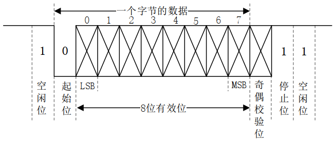
data bits: data bits are the actual data to be transmitted. The data bits can be 5 ~ 8 bits. We generally transmit data according to bytes. One byte has 8 bits, so the data bits are usually 8 bits. The low bit is first transmitted, and the high bit is last transmitted.
the specific communication format is shown in the figure below:

1.2 UART level standard
the general interface levels of UART include TTL and RS-232. Generally, there are pins such as TXD and RXD on the development board. The low level of these pins represents logic 0 and the high level represents logic 1. This is the TTL level. RS-232 adopts differential line, - 3~-15V represents logic 1 and + 3~+15V represents logic 0.
1.3 introduction to i.mx6u UART
I.MX6U has 8 UART S in total, and its main features are as follows:
① Compatible with TIA/EIA-232F standard, the speed can be up to 5Mbit/S.
② Support serial IR interface, compatible with IrDA, up to 115.2Kbit/s.
③ Support 9-bit or multi node mode (RS-485).
④ 1 or 2 stop bits.
⑥ Programmable parity (odd and even).
⑦ Automatic baud rate detection (up to 115.2Kbit/S)
the clock source of UART is controlled by register CCM_ UART of cscdr1_ CLK_ Sel (bit) bit. When it is 0, the clock source of UART is pll3_80m(80MHz). If it is 1, the clock source of UART is osc_clk(24M), generally pll3_80m is used as the clock source of UART. Register CCM_ UART of cscdr1_ CLK_ The podf (bit5:0) bit is the clock division value of UART. It can be set to 0 ~ 63, corresponding to 1 ~ 64 division respectively. Generally, it is set to 1 Division. Therefore, the final clock entering UART is 80MHz.
by setting register UARTx_UFCR , UARTx_UBIR and UARTx_UBMR, we can get the baud rate we want. Register uartx_ In ufcr, we need to use bit RFDIV(bit9:7) to set the frequency division of the reference clock, while UBMR and UBIR directly use UARTx_UBIR and uartx_ The value in UBMR register is calculated as follows:

finally, let's look at the register UARTx_URXD and UARTx_UTXD, these two registers are the receiving and transmitting data registers of UART respectively, and the lower eight bits of these two registers are the received and transmitted data. Read register UARTx_URXD can obtain the received data. If you want to send data through UART, write the data directly to the register UARTx_UTXD is enough.
to sum up, the configuration steps of UART1 are as follows:
1. Set the clock source of UART1
set the clock source of UART to pll3_80m, setting register CCM_ UART of cscdr1_ CLK_ The SEL bit is 0.
2. Initialize UART1
initialize the IO used by uart1 and set the register uart1 of UART1_UCR1~UART1_UCR3, setting contents include baud rate, parity, stop bit, data bit, etc.
3. Enable UART1
UART1 can be enabled after UART1 initialization. Set register UART1_ Bit UARTEN of ucr1 is 1.
4. Write UART1 data transceiver function
write two functions for UART1 data sending and receiving operation.
2. Coding
we write a total of 10 functions in the c file of UART, uart_init is used to initialize the IO related to UART1, set the baud rate, word length, stop bit and verification mode of UART1, and finally enable UART1. uart_io_init, used to initialize IO used by UART1. uart_setbaudrate is transplanted from the official SDK package of NXP to set the baud rate. uart_disable and uart_enable is to enable and close UART1 respectively. The sixth function is uart_softreset, used to reset the specified UART by software. The seventh function is putc, which is used to send one byte of data through UART1. The eighth function is puts, which is used to send a string of data through UART1. The ninth function is getc, which is used to obtain a byte of data through UART1. The last function is raise, which is an empty function to prevent the compiler from reporting errors.
/*
 * @description : Initialize serial port 1 with a baud rate of 115200
 * @param		: nothing
 * @return		: nothing
 */
void uart_init(void)
{
	/* 1,Initialize serial port IO 			*/
	uart_io_init();

	/* 2,Initialize UART1  			*/
	uart_disable(UART1);	/* Close UART1 first 		*/
	uart_softreset(UART1);	/* Software reset UART1 		*/

	UART1->
UCR1 = 0;		/* Clear the UCR1 register first */

	/*
     * Set the UCR1 register of UART and turn off the automatic baud rate
     * bit14: 0 Turn off automatic baud rate detection and set the baud rate ourselves
	 */
	UART1->UCR1 &= ~(1<<14);

	/*
     * Set UCR2 register of UART, including word length, stop bit, verification mode, and turn off RTS hardware flow control
     * bit14: 1 Ignore RTS pin
	 * bit8: 0 Turn off parity
     * bit6: 0 1 Bit stop bit
 	 * bit5: 1 8 Digit data bit
 	 * bit2: 1 Open send
 	 * bit1: 1 Open receive
	 */
	UART1->UCR2 |= (1<<14) | (1<<5) | (1<<2) | (1<<1);

	/*
     * UART1 UCR3 register for
     * bit2: 1 Must be set to 1! Refer to IMX6ULL reference manual page 3624
	 */
	UART1->UCR3 |= 1<<2;

	/*
	 * set baud rate
	 * Baud rate calculation formula: Baud Rate = Ref Freq / (16 * (UBMR + 1)/(UBIR+1))
	 * If you want to set the baud rate to 115200, you can use the following parameters:
	 * Ref Freq = 80M That is, bit9:7=101 of register UFCR indicates 1 frequency division
	 * UBMR = 3124
 	 * UBIR =  71
 	 * Therefore, baud rate = 80000000 / (16 * (3124 + 1) / (71 + 1)) = 80000000 / (16 * 3125 / 72) = (80000000 * 72) / (16 * 3125) = 115200
	 */
	UART1->UFCR = 5<<7; //ref freq equals ipg_clk/1=80Mhz
	UART1->UBIR = 71;
	UART1->UBMR = 3124;

#if 0
	 uart_setbaudrate(UART1, 115200, 80000000); /* set baud rate */
#endif

	/* Enable serial port */
	uart_enable(UART1);
}

/*
 * @description : Initialize the IO pin used by serial port 1
 * @param		: nothing
 * @return		: nothing
 */
void uart_io_init(void)
{
	/* 1,Initialize IO multiplexing
     * UART1_RXD -> UART1_TX_DATA
     * UART1_TXD -> UART1_RX_DATA
	 */
	IOMUXC_SetPinMux(IOMUXC_UART1_TX_DATA_UART1_TX,0);	/* Multiplexed to UART1_TX */
	IOMUXC_SetPinMux(IOMUXC_UART1_RX_DATA_UART1_RX,0);	/* Multiplexed to UART1_RX */

	/* 2,Configure UART1_TX_DATA,UART1_ RX_ IO attribute of data
 	*bit 16:0 HYS close
 	*bit [15:14]: 00 Default 100K drop-down
 	*bit [13]: 0 keeper function
 	*bit [12]: 1 pull/keeper Enable
 	*bit [11]: 0 Turn off the open circuit output
 	*bit [7:6]: 10 Speed 100Mhz
 	*bit [5:3]: 110 Driving capacity R0/6
 	*bit [0]: 0 Low conversion rate
 	*/
	IOMUXC_SetPinConfig(IOMUXC_UART1_TX_DATA_UART1_TX,0x10B0);
	IOMUXC_SetPinConfig(IOMUXC_UART1_RX_DATA_UART1_RX,0x10B0);
}

/*
 * @description 		: Baud rate calculation formula,
 *    			  	  	  This function can be used to calculate the UFCR corresponding to the specified serial port,
 * 				          UBIR And UBMR
 * @param - base		: Serial port to be calculated.
 * @param - baudrate	: Baud rate to use.
 * @param - srcclock_hz	:Serial port clock source frequency, unit: Hz
 * @return		: nothing
 */
void uart_setbaudrate(UART_Type *base, unsigned int baudrate, unsigned int srcclock_hz)
{
    uint32_t numerator = 0u;		//molecule
    uint32_t denominator = 0U;		//denominator
    uint32_t divisor = 0U;
    uint32_t refFreqDiv = 0U;
    uint32_t divider = 1U;
    uint64_t baudDiff = 0U;
    uint64_t tempNumerator = 0U;
    uint32_t tempDenominator = 0u;

    /* get the approximately maximum divisor */
    numerator = srcclock_hz;
    denominator = baudrate << 4;
    divisor = 1;

    while (denominator != 0)
    {
        divisor = denominator;
        denominator = numerator % denominator;
        numerator = divisor;
    }

    numerator = srcclock_hz / divisor;
    denominator = (baudrate << 4) / divisor;

    /* numerator ranges from 1 ~ 7 * 64k */
    /* denominator ranges from 1 ~ 64k */
    if ((numerator > (UART_UBIR_INC_MASK * 7)) || (denominator > UART_UBIR_INC_MASK))
    {
        uint32_t m = (numerator - 1) / (UART_UBIR_INC_MASK * 7) + 1;
        uint32_t n = (denominator - 1) / UART_UBIR_INC_MASK + 1;
        uint32_t max = m > n ? m : n;
        numerator /= max;
        denominator /= max;
        if (0 == numerator)
        {
            numerator = 1;
        }
        if (0 == denominator)
        {
            denominator = 1;
        }
    }
    divider = (numerator - 1) / UART_UBIR_INC_MASK + 1;

    switch (divider)
    {
        case 1:
            refFreqDiv = 0x05;
            break;
        case 2:
            refFreqDiv = 0x04;
            break;
        case 3:
            refFreqDiv = 0x03;
            break;
        case 4:
            refFreqDiv = 0x02;
            break;
        case 5:
            refFreqDiv = 0x01;
            break;
        case 6:
            refFreqDiv = 0x00;
            break;
        case 7:
            refFreqDiv = 0x06;
            break;
        default:
            refFreqDiv = 0x05;
            break;
    }
    /* Compare the difference between baudRate_Bps and calculated baud rate.
     * Baud Rate = Ref Freq / (16 * (UBMR + 1)/(UBIR+1)).
     * baudDiff = (srcClock_Hz/divider)/( 16 * ((numerator / divider)/ denominator).
     */
    tempNumerator = srcclock_hz;
    tempDenominator = (numerator << 4);
    divisor = 1;
    /* get the approximately maximum divisor */
    while (tempDenominator != 0)
    {
        divisor = tempDenominator;
        tempDenominator = tempNumerator % tempDenominator;
        tempNumerator = divisor;
    }
    tempNumerator = srcclock_hz / divisor;
    tempDenominator = (numerator << 4) / divisor;
    baudDiff = (tempNumerator * denominator) / tempDenominator;
    baudDiff = (baudDiff >= baudrate) ? (baudDiff - baudrate) : (baudrate - baudDiff);

    if (baudDiff < (baudrate / 100) * 3)
    {
        base->UFCR &= ~UART_UFCR_RFDIV_MASK;
        base->UFCR |= UART_UFCR_RFDIV(refFreqDiv);
        base->UBIR = UART_UBIR_INC(denominator - 1); //Write the UBIR register first, and then write the UBMR register, page 3592
        base->UBMR = UART_UBMR_MOD(numerator / divider - 1);
    }
}

/*
 * @description : Close the specified UART
 * @param - base: UART to close
 * @return		: nothing
 */
void uart_disable(UART_Type *base)
{
	base->UCR1 &= ~(1<<0);
}

/*
 * @description : Open the specified UART
 * @param - base: UART to open
 * @return		: nothing
 */
void uart_enable(UART_Type *base)
{
	base->UCR1 |= (1<<0);
}

/*
 * @description : Resets the specified UART
 * @param - base: UART to reset
 * @return		: nothing
 */
void uart_softreset(UART_Type *base)
{
	base->UCR2 &= ~(1<<0); 			/* UCR2 bit0 of is 0, reset UART  	  	*/
	while((base->UCR2 & 0x1) == 0); /* Wait for reset to complete 					*/
}

/*
 * @description : Send a character
 * @param - c	: Characters to send
 * @return		: nothing
 */
void putc(unsigned char c)
{
	while(((UART1->USR2 >> 3) &0X01) == 0);/* Wait for the last transmission to complete */
	UART1->UTXD = c & 0XFF; 				/* send data */
}

/*
 * @description : Send a string
 * @param - str	: String to send
 * @return		: nothing
 */
void puts(char *str)
{
	char *p = str;

	while(*p)
		putc(*p++);
}

/*
 * @description : Receive a character
 * @param 		: nothing
 * @return		: Characters received
 */
unsigned char getc(void)
{
	while((UART1->USR2 & 0x1) == 0);/* Wait for reception to complete */
	return UART1->URXD;				/* Return received data */
}

/*
 * @description : Prevent compiler errors
 * @param 		: nothing
 * @return		: nothing
 */
void raise(int sig_nr)
{

}
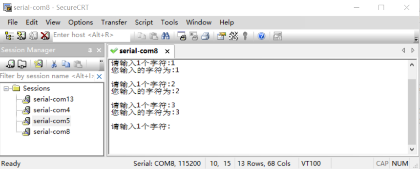
we just need to be in main Calling uart_ in C function Init, and then accept the characters from the PC in the while loop and send them back, which will be displayed in the serial port debugging assistant on the PC.
/*
 * @description	: main function
 * @param 		: nothing
 * @return 		: nothing
 */
int main(void)
{
	unsigned char a=0;
	unsigned char state = OFF;

	int_init(); 				/* Initialization interrupt (must be called first!) */
	imx6u_clkinit();			/* Initialize system clock 			*/
	delay_init();				/* Initialization delay 			*/
	clk_enable();				/* Enable all clocks 			*/
	led_init();					/* Initialize led 			*/
	beep_init();				/* Initialize beep	 		*/
	uart_init();				/* Initialize serial port, baud rate 115200 */

	while(1)
	{
		puts("Please enter 1 character:");
		a=getc();
		putc(a);	//Echo function
		puts("\r\n");

		//Displays the characters entered
		puts("The character you entered is:");
		putc(a);
		puts("\r\n\r\n");

		state = !state;
		led_switch(LED0,state);
	}
	return 0;
}
finally, we found that serial port 1 of I.MX6U can work normally in the serial port debugger SecureCRT.
