Test purpose
- Test the interconnection of different network segments through three-layer switches
- The three-layer switch is directly connected to the router to connect the external network to realize the connection between the host and the external network
Application scenario
- The simulation implementation can be used for interconnection of different network segments such as different floors, different departments / departments.
- The simulation implementation can be used to connect the external network by different departments / departments.
testing environment
- eNSP 1.3.00.100 V100R003C000SPC100
- window 10
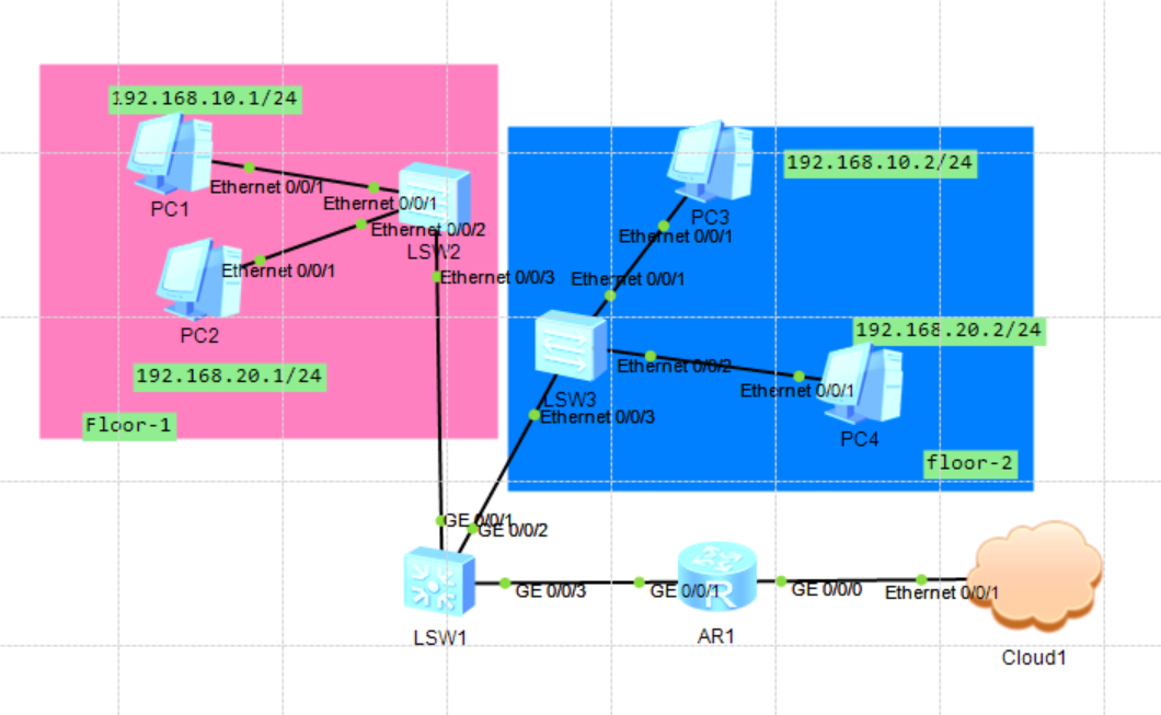
Test topology
- Area floor 1 and floor 2 are 192.168 respectively 10.0/24,192.168. 20.0/24 segment network.
- There is a second floor switch on each floor, and the host access port is added.
- Add a three-layer core switch to realize the interconnection of all switches.
- A router is added to connect the external network and the core switch. Different network ends can be connected to the external network according to the routing configuration.
- All hosts configure IP addresses manually. Dynamically configure IP reference eNSP network segment host interconnection DHCP
- All hosts are interconnected through switches, and the same network segment can be directly interconnected by default.
Topology configuration
Realize PC interconnection of different network segments
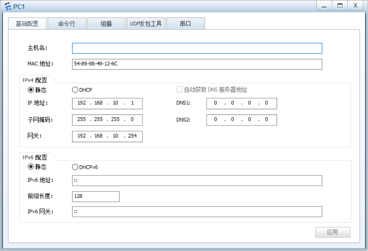
PC1 configuration
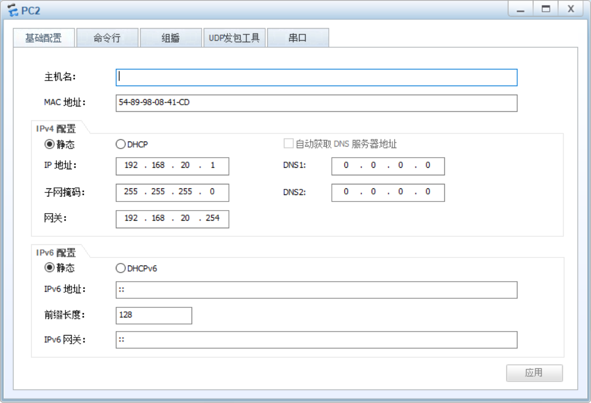
PC2 configuration
PC3 configuration

PC4 configuration

Switch configuration
L2 switch LSW2 configuration
- Modify the switch name.
- Add VLAN 10, 20.
- Configure Ethernet 0/0/1 to support access to VLAN 10.
- Configure Ethernet 0/0/2 to support access to VLAN 20.
- Configure Ethernet 0/0/3 as trunk binding port, and support VLAN 10 and VLAN 20 data transmission at the same time.
<Huawei>sys
Enter system view, return user view with Ctrl+Z.
[Huawei]sysname LSW2
[LSW2]
[LSW2]vlan batch 10 20
[LSW2]interface Ethernet 0/0/1
[LSW2-Ethernet0/0/1]port link-type access
[LSW2-Ethernet0/0/1]port default vlan 10
[LSW2-Ethernet0/0/1]quit
[LSW2]
[LSW2]interface Ethernet 0/0/2
[LSW2-Ethernet0/0/2]port link-type access
[LSW2-Ethernet0/0/2]port default vlan 20
[LSW2-Ethernet0/0/2]quit
[LSW2]
[LSW2]interface Ethernet 0/0/3
[LSW2-Ethernet0/0/3]port link-type trunk
[LSW2-Ethernet0/0/3]port trunk allow-pass vlan 10 20
[LSW2-Ethernet0/0/3]quit
[LSW2]
[LSW2]quit
<LSW2>save
The current configuration will be written to the device.
Are you sure to continue?[Y/N]y
Info: Please input the file name ( *.cfg, *.zip ) [vrpcfg.zip]:
Dec 23 2021 11:09:16-08:00 LSW2 %%01CFM/4/SAVE(l)[0]:The user chose Y when decid
ing whether to save the configuration to the device.
Now saving the current configuration to the slot 0.
Save the configuration successfully.
<LSW2>
L2 switch LSW3 configuration
- Modify the switch name.
- Add VLAN 10, 20.
- Configure Ethernet 0/0/1 to support access to VLAN 10.
- Configure Ethernet 0/0/2 to support access to VLAN 20.
- Configure Ethernet 0/0/3 as trunk binding port, and support VLAN 10 and VLAN 20 data transmission at the same time.
<Huawei>sys
Enter system view, return user view with Ctrl+Z.
[Huawei]sysname LSW3
[LSW3]
[LSW3]vlan batch 10 20
[LSW3]interface Ethernet 0/0/1
[LSW3-Ethernet0/0/1]port link-type access
[LSW3-Ethernet0/0/1]port default vlan 10
[LSW3-Ethernet0/0/1]quit
[LSW3]
[LSW3]interface Ethernet 0/0/2
[LSW3-Ethernet0/0/2]port link-type access
[LSW3-Ethernet0/0/2]port default vlan 20
[LSW3-Ethernet0/0/2]quit
[LSW3]
[LSW3]interface Ethernet 0/0/3
[LSW3-Ethernet0/0/3]port link-type trunk
[LSW3-Ethernet0/0/3]port trunk allow-pass vlan 10 20
[LSW3-Ethernet0/0/3]quit
[LSW3]
[LSW3]quit
<LWS3>save
The current configuration will be written to the device.
Are you sure to continue?[Y/N]y
Info: Please input the file name ( *.cfg, *.zip ) [vrpcfg.zip]:
Dec 23 2021 11:14:54-08:00 LWS3 %%01CFM/4/SAVE(l)[0]:The user chose Y when decid
ing whether to save the configuration to the device.
Now saving the current configuration to the slot 0.
Save the configuration successfully.
<LWS3>
Layer 3 switch LSW1 configuration
- Modify the switch name.
- Add VLAN 10, 20.
- VLAN 10 IP address 192.168 10.254,192.168. 10.0/24 network segment gateway address.
- VLAN 20 IP address 192.168 20.254,192.168. 20.0/24 network segment gateway address.
- Configure GE 0/0/1 as trunk binding port, and support VLAN 10 and VLAN 20 data transmission at the same time.
- Configure GE 0/0/2 as trunk binding port, and support VLAN 10 and VLAN 20 data transmission at the same time.
<Huawei>sys
Enter system view, return user view with Ctrl+Z.
[Huawei]sysname LSW1
[LSW1]
[LSW1]vlan batch 10 20
[LSW1]
[LSW1]interface Vlanif 10
[LSW1-Vlanif10]ip address 192.168.10.254 24
[LSW1-Vlanif10]quit
[LSW1]
[LSW1]interface Vlanif 20
[LSW1-Vlanif20]ip address 192.168.20.254 24
[LSW1-Vlanif20]quit
[LSW1]
[LSW1]interface GigabitEthernet 0/0/1
[LSW1-GigabitEthernet0/0/1]port link-type trunk
[LSW1-GigabitEthernet0/0/1]port trunk allow-pass vlan 10 20
[LSW1-GigabitEthernet0/0/1]quit
[LSW1]
[LSW1]interface GigabitEthernet 0/0/2
[LSW1-GigabitEthernet0/0/2]port link-type trunk
[LSW1-GigabitEthernet0/0/2]port trunk allow-pass vlan 10 20
[LSW1-GigabitEthernet0/0/1]quit
[LSW1]quit
<LSW1>save
The current configuration will be written to the device.
Are you sure to continue?[Y/N]y
Info: Please input the file name ( *.cfg, *.zip ) [vrpcfg.zip]:
Dec 23 2021 11:30:19-08:00 LSW1 %%01CFM/4/SAVE(l)[4]:The user chose Y when decid
ing whether to save the configuration to the device.
Now saving the current configuration to the slot 0.
Save the configuration successfully.
<LSW1>
PC interconnection test
PING test 192.168.10.2192.168.20.1192.168.20.2 on PC1 (192.168.10.1). So far, the interconnection of different network segments through VLAN has been realized.
PC>ipconfig

Link local IPv6 address...........: fe80::5689:98ff:fe49:126c
IPv6 address......................: :: / 128
IPv6 gateway......................: ::
IPv4 address......................: 192.168.10.1
Subnet mask.......................: 255.255.255.0
Gateway...........................: 192.168.10.254
Physical address..................: 54-89-98-49-12-6C
DNS server........................:

PC>ping 192.168.10.2

Ping 192.168.10.2: 32 data bytes, Press Ctrl_C to break
From 192.168.10.2: bytes=32 seq=1 ttl=128 time=78 ms
From 192.168.10.2: bytes=32 seq=2 ttl=128 time=94 ms
From 192.168.10.2: bytes=32 seq=3 ttl=128 time=63 ms
From 192.168.10.2: bytes=32 seq=4 ttl=128 time=78 ms
From 192.168.10.2: bytes=32 seq=5 ttl=128 time=62 ms

--- 192.168.10.2 ping statistics ---
  5 packet(s) transmitted
  5 packet(s) received
  0.00% packet loss
  round-trip min/avg/max = 62/75/94 ms

PC>ping 192.168.20.1

Ping 192.168.20.1: 32 data bytes, Press Ctrl_C to break
From 192.168.20.1: bytes=32 seq=1 ttl=127 time=93 ms
From 192.168.20.1: bytes=32 seq=2 ttl=127 time=78 ms
From 192.168.20.1: bytes=32 seq=3 ttl=127 time=63 ms
From 192.168.20.1: bytes=32 seq=4 ttl=127 time=78 ms
From 192.168.20.1: bytes=32 seq=5 ttl=127 time=94 ms

--- 192.168.20.1 ping statistics ---
  5 packet(s) transmitted
  5 packet(s) received
  0.00% packet loss
  round-trip min/avg/max = 63/81/94 ms

PC>ping 192.168.20.2

Ping 192.168.20.2: 32 data bytes, Press Ctrl_C to break
From 192.168.20.2: bytes=32 seq=1 ttl=127 time=79 ms
From 192.168.20.2: bytes=32 seq=2 ttl=127 time=78 ms
From 192.168.20.2: bytes=32 seq=3 ttl=127 time=78 ms
From 192.168.20.2: bytes=32 seq=4 ttl=127 time=78 ms
From 192.168.20.2: bytes=32 seq=5 ttl=127 time=78 ms

--- 192.168.20.2 ping statistics ---
  5 packet(s) transmitted
  5 packet(s) received
  0.00% packet loss
  round-trip min/avg/max = 78/78/79 ms

PC>
The LAN is connected to the external network through a router
PC configuration
- Add DNS domain name configuration 8.8 8.8. For subsequent tests, you can ping the test domain name directly.

Layer 3 switch LSW1 configuration
- Add a VLAN 100,
- Configure VLAN 100 port address 192.168 100.1/24
- Configure GE 0/0/3 to access VLAN 100
- Configure the default route, and the next one is the router docking interface address 192.168 one hundred point two
[LSW1]vlan batch 100
[LSW1]
[LSW1]interface Vlanif 100
[LSW1-Vlanif100]ip address 192.168.100.1 24
[LSW1-Vlanif100]quit
[LSW1]
[LSW1]interface GigabitEthernet 0/0/3
[LSW1-GigabitEthernet0/0/3]port link-type access
[LSW1-GigabitEthernet0/0/3]port default vlan 100
[LSW1-GigabitEthernet0/0/3]quit
[LSW1]
[LSW1]ip route-static 0.0.0.0 0.0.0.0 192.168.100.2
<LSW1>save
The current configuration will be written to the device.
Are you sure to continue?[Y/N]y
Now saving the current configuration to the slot 0.
Dec 23 2021 13:23:53-08:00 LSW1 %%01CFM/4/SAVE(l)[7]:The user chose Y when decid
ing whether to save the configuration to the device.
Save the configuration successfully.
<LSW1>
Router AR1 configuration
- Modify the router name.
- Configure GE 0/0/1 address 192.168 100.2/24, realizing interconnection with layer 3 switch
- Configure static routing to realize network segment 192.168 0.0/16, through the next one, the switch docking interface address is 192.168 one hundred point one
- Configure access rules to allow 192.168 0.0/16, access the external network through the router
- Configure GE 0/0/0 to connect with cloud image.
- Configure GE 0/0/0 to support NAT conversion of local address segment 192.168 0.0/16 access to external network.
<Huawei>sys
Enter system view, return user view with Ctrl+Z.
[Huawei]sysname AR1
[AR1]
[AR1]interface GigabitEthernet 0/0/1
[AR1-GigabitEthernet0/0/1]ip address 192.168.100.2 255.255.255.0
[AR1-GigabitEthernet0/0/1]quit
[AR1]
[AR1]ip route-static 192.168.0.0 255.255.0.0 192.168.100.1
[AR1]
[AR1]acl number 2000
[AR1-acl-basic-2000]rule 5 permit source 192.168.0.0 0.0.255.255
[AR1-acl-basic-2000]quit
[AR1]
[AR1]interface GigabitEthernet 0/0/0
[AR1-GigabitEthernet0/0/0]ip address 192.168.137.2 255.255.255.0
[AR1-GigabitEthernet0/0/0]nat outbound 2000
[AR1-GigabitEthernet0/0/0]quit
[AR1]quit
<AR1>save
  The current configuration will be written to the device.
  Are you sure to continue? (y/n)[n]:y
  It will take several minutes to save configuration file, please wait......
  Configuration file had been saved successfully
  Note: The configuration file will take effect after being activated
<AR1>
Router connection cloud map connection external network
Refer to another blog post eNSP router connecting to external network
PC test connection external network
PC>ipconfig

Link local IPv6 address...........: fe80::5689:98ff:fe49:126c
IPv6 address......................: :: / 128
IPv6 gateway......................: ::
IPv4 address......................: 192.168.10.1
Subnet mask.......................: 255.255.255.0
Gateway...........................: 192.168.10.254
Physical address..................: 54-89-98-49-12-6C
DNS server........................: 8.8.8.8


PC>ping 192.168.100.2

Ping 192.168.100.2: 32 data bytes, Press Ctrl_C to break
From 192.168.100.2: bytes=32 seq=1 ttl=254 time=62 ms
From 192.168.100.2: bytes=32 seq=2 ttl=254 time=47 ms
From 192.168.100.2: bytes=32 seq=3 ttl=254 time=62 ms
From 192.168.100.2: bytes=32 seq=4 ttl=254 time=79 ms
From 192.168.100.2: bytes=32 seq=5 ttl=254 time=62 ms

--- 192.168.100.2 ping statistics ---
  5 packet(s) transmitted
  5 packet(s) received
  0.00% packet loss
  round-trip min/avg/max = 47/62/79 ms

PC>ping 8.8.8.8

Ping 8.8.8.8: 32 data bytes, Press Ctrl_C to break
From 8.8.8.8: bytes=32 seq=1 ttl=109 time=125 ms
From 8.8.8.8: bytes=32 seq=2 ttl=109 time=110 ms
From 8.8.8.8: bytes=32 seq=3 ttl=109 time=109 ms
From 8.8.8.8: bytes=32 seq=4 ttl=109 time=109 ms
From 8.8.8.8: bytes=32 seq=5 ttl=109 time=125 ms

--- 8.8.8.8 ping statistics ---
  5 packet(s) transmitted
  5 packet(s) received
  0.00% packet loss
  round-trip min/avg/max = 109/115/125 ms

PC>ping www.baidu.com

www.baidu.com -> www.a.shifen.com

Ping www.a.shifen.com [180.101.49.11]: 32 data bytes, Press Ctrl_C to break
From 180.101.49.11: bytes=32 seq=1 ttl=48 time=63 ms
From 180.101.49.11: bytes=32 seq=2 ttl=48 time=78 ms
From 180.101.49.11: bytes=32 seq=3 ttl=48 time=47 ms
From 180.101.49.11: bytes=32 seq=4 ttl=48 time=63 ms
From 180.101.49.11: bytes=32 seq=5 ttl=48 time=62 ms

--- 180.101.49.11 ping statistics ---
  5 packet(s) transmitted
  5 packet(s) received
  0.00% packet loss
  round-trip min/avg/max = 47/62/78 ms

PC>