What is cluster
- A group of computers interconnected by a high-speed network and managed in a single system mode.
- Many servers are put together to provide the same service, which looks like only one server in the client.
- It can obtain relatively high benefits in performance, reliability and flexibility at a lower cost.
- Task scheduling is the core technology of cluster system.
Cluster classification
-
High performance computing cluster HPC
- solve complex scientific problems through parallel applications developed in clusters -
Load balancing (LB) cluster
- the client load is shared equally in the computer cluster as much as possible -
High availability (HA) cluster
- avoid single point of failure, when a system fails, it can be quickly migrated
Load balancing type
-DNS load balancing
DNS load balancing is the most basic and simple way. A domain name is resolved to multiple IPS through DNS, and each IP corresponds to different server instances, so the traffic scheduling is completed. Although the conventional load balancer is not used, it does complete the function of simple load balancing.
-Hardware load balancing
hardware load balancing is to realize load balancing function through special hardware equipment, similar to switch and router, which is a special network equipment for load balancing. At present, there are two typical hardware load balancing devices in the industry: F5 and A10. This kind of equipment has strong performance and powerful function, but its price is very expensive. Generally, only "tuhao" companies can use this kind of equipment, which can not be afforded by ordinary business level companies. Secondly, the business volume is not so large, and using these equipment is also a waste.
-Software load balancing
software load balancing can run load balancing software on ordinary servers to realize load balancing function. At present, Nginx, HAproxy and LVS are common.
difference:
.
. The default load balancing software used by OpenStack is HAproxy
.
Introduction to load balancing LVS
the architecture and principle of LB cluster is very simple, that is, when the user's request comes, it will be directly distributed to the Director Server, and then it will distribute the user's request to the back-end real server intelligently and evenly according to the set scheduling algorithm. In order to avoid different data requested by users on different machines, shared storage is needed to ensure that the data requested by all users is the same.
LVS is the abbreviation of Linux Virtual Server, that is, Linux Virtual Server. This is an open source project initiated by Dr. Zhang wensong. Now LVS is a part of Linux kernel standard. The technical goal of LVS is to achieve a high performance and high availability Linux Server cluster through LVS load balancing technology and Linux operating system, which has good reliability, scalability and operability. In order to achieve the best performance at a low cost. LVS is an open source software project to realize load balancing cluster. LVS architecture can be logically divided into scheduling layer, Server cluster layer and shared storage layer.
Basic working principle of LVS
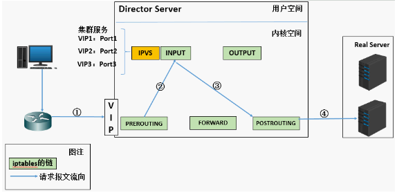
1. When the user initiates a request to the load balancing scheduler (Director Server), the scheduler sends the request to the kernel space
2. The pre routing chain will first receive the user's request, judge whether the target IP is the local IP, and send the data packet to the INPUT chain
3.IPVS works on the INPUT chain. When the user request arrives at INPUT, IPVS will compare the user request with the defined cluster service. If the user request is the defined cluster service, then IPVS will forcibly modify the target IP address and port in the packet and send the new packet to the post routing chain
4. After receiving the packet, the posting link finds that the destination IP address just happens to be its own back-end server. At this time, the packet is finally sent to the back-end server by routing
LVS load balancing scheduling algorithm
- LVS currently implements 10 scheduling algorithms
- There are four common scheduling algorithms
- polling
- distribute client requests to Real Server evenly
- weighted polling
Polling scheduling based on Real Server weight
- minimum connection
- select the server with the least connections
- weighted least connection
- select the server with the least connections according to the Real Server weight value
- source address hash
LVS cluster composition
- front end: load balancing layer
- composed of one or more load schedulers
- middle: server group layer
- consists of a set of servers that actually run application services
- bottom: data sharing storage tier
- storage area that provides shared storage space
Related terms
DS: Director Server. Refers to the front-end load balancer node.
RS: Real Server. Back end real working server.
CIP: Client IP, indicating the Client IP address.
VIP: Virtual IP, which indicates the IP address that load balancing provides for external access. Generally, load balancing IP will be highly available through Virtual IP.
RIP: RealServer IP, which represents the real server IP address of the load balancing backend.
DIP: Director IP, which indicates the IP address of the communication between the load balancing and the back-end server.
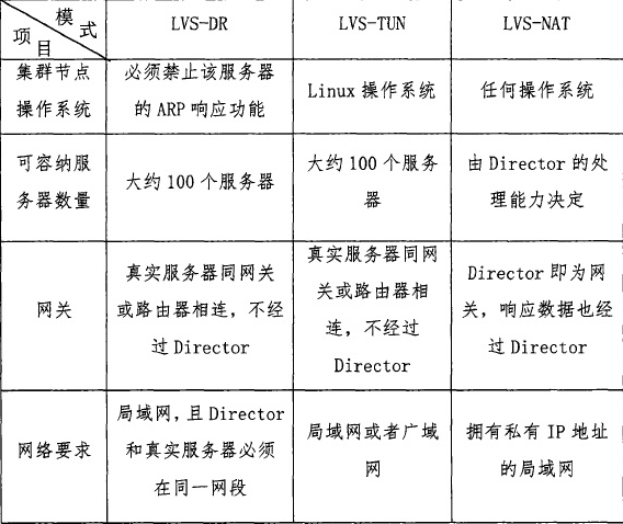
LVS working mode
LVS/NAT: network address translation
- virtual server through network address translation
- scheduler performance becomes a bottleneck in large concurrent access
-LVS/DR: direct routing
- direct use of routing technology to achieve virtual server
- the node server needs to be configured with VIP, pay attention to MAC address broadcast
-LVS/TUN: IP tunnel
- tunnel virtual server
Principle of each working mode of LVS
For more details, please refer to the blog: https://blog.csdn.net/liwei0526vip/article/details/103104483
1. Network address translation (LVS-NAT)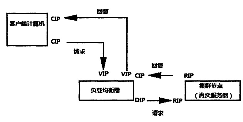
1. When the user requests to arrive at the Director Server, the requested data message will first arrive at the preouting chain in the kernel space. At this time, the source IP of the message is CIP and the target IP is VIP.

2.PREROUTING checks that the destination IP of the packet is local and sends the packet to the INPUT chain

3.IPVS compares whether the service requested by the packet is a cluster service. If so, modify the destination IP address of the packet to the back-end server IP, and then send the packet to the posting chain. At this time, the source IP of the message is CIP, and the target IP is rip 4. The posting chain sends the packet to the Real Server through routing

5.Real Server finds that the target is its own IP, and starts to build response message to send back to Director Server. At this time, the source IP of the message is RIP, and the target IP is CIP

6. Before responding to the client, the director server will change the source IP address to its own VIP address, and then respond to the client. At this time, the source IP of the message is VIP and the target IP is CIP
2. Direct routing (LVS-DR)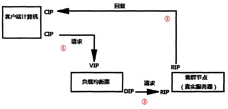
1. When the user requests to arrive at the Director Server, the requested data message will first arrive at the preouting chain in the kernel space. At this time, the source IP of the message is CIP and the target IP is VIP.

2.PREROUTING checks that the destination IP of the packet is local and sends the packet to the INPUT chain

3.IPVS compares whether the service requested by the packet is a cluster service. If so, change the source MAC address [CIP] in the request message to the MAC address of DIP, change the destination MAC address [VIP] to the MAC address of RIP, and then send the packet to the post routing chain [LVS]. At this time, neither the source IP nor the destination IP has been modified. Only the MAC address with the source MAC address of DIP and the destination MAC address of RIP have been modified

4. Since DS and RS are in the same network, they are transmitted through two layers. The post routing chain checks the MAC address [ARP broadcast] whose target MAC address is RIP, and then the packet will be sent to the Real Server.

5.RS finds that the MAC address of the request message is its own MAC address, so it receives the message. After processing, the response message is transmitted to eth0 network card through its own lo interface, and then [ARP broadcast] is sent out. At this time, the source IP address is VIP and the target IP is CIP

be careful:
 If there is no external IP set for RS, RS will broadcast ARP to find CIP. If there is no internal network, it will be submitted to the gateway. The gateway will directly send out the external network, which may increase the pressure on the gateway

6. The response message is finally delivered to the client
Features: a Mac address is added to let the real server find the client and send the response message directly. In the whole process, the client IP (CIP) and the load balancer IP have not changed, but the Mac address has changed. The purpose is to let the client know that you send the requested message and respond to your message by one person.
3.IP tunnel (LVS-TUN)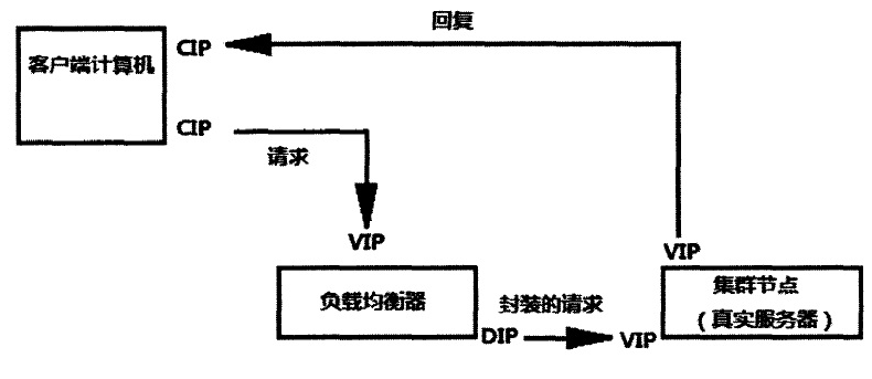
1. When the user requests to arrive at the Director Server, the requested data message will first arrive at the preouting chain in the kernel space. At this time, the source IP of the message is CIP and the target IP is VIP.

2.PREROUTING checks that the destination IP of the packet is local and sends the packet to the INPUT chain

3.IPVS compares whether the service requested by the packet is a cluster service. If so, a layer of IP message is encapsulated at the first part of the request message. The source IP is DIP and the target IP is RIP. Then send it to the posting chain. At this time, the source IP is DIP, the target IP is RIP ④, and the posting chain sends the data packet to RS according to the latest encapsulated IP message (because there is an additional IP header in the outer layer, it can be understood that it is transmitted through the tunnel at this time). At this time, the source IP is DIP and the target IP is RIP

4. When RS receives the message and finds that it is its own IP address, it will receive the message. After removing the outermost IP, it will be found that there is a layer of IP head inside, and the target is its own lo interface VIP. Then RS starts to process the request. After processing, RS will send it to eth0 network card through lo interface, and then transmit it to the outside. At this time, the source IP address is VIP and the destination IP is CIP

5. The response message is finally delivered to the client
Comparison of three working modes
ipvsadm command options
  ipvsadm -A create virtual server
  ipvsadm -E modify virtual server
  ipvsadm -D delete virtual server

  ipvsadm -t set cluster address (VIP,Virtual IP)
  ipvsadm -s specifies the clustering algorithm ----- > RR (polling), WRR (weighted polling), LC (least connection), WLC (weighted least connection), sh(ip_hash)

  ipvsadm -a add real server
  ipvsadm -e modify real server
  ipvsadm -d delete real server

  ipvsadm -r specifies the address of the real server
  ipvsadm -w sets the weight for the node server, which is 1 by default

  ipvsadm -C clear all
  ipvsadm -L view LVS rule table -- > usually used with n, output (- Ln) in digital form

  ipvsadm -m uses NAT mode
  Ipvsadm-g uses DR mode
  ipvsadm -i using TUN mode
LVS-DR mode Practice
Environment introduction
client: 192.168.2.132/24
load balancing server: ens33:0 (VIP): 192.168.2.133/24 ens33 (DIP): 192.168.2.130/24 (test3)
backend server 1: 192.168.2.128/24 (localhost) lo:0:192.168.2.133/32
backend server 2: 192.168.2.129/24 (test2) lo:0:192.168.2.133/32
kernel version: 3.10.0-862.el7.x86_ Sixty-four
system version: CentOS 7.5
explain:
CIP is the IP address of the client;
VIP is the IP address to provide services to clients;
RIP is the real IP address of the back-end server;
DIP is the IP address of the dispatcher communicating with the back-end server (VIP must be configured in the virtual interface)
Meaning of network card:
cat /etc/sysconfig/network-scripts/ifcfg-ens33
  TYPE=Ethernet        #Network card type
  DEVICE=ens33          #Network card interface name
  ONBOOT=yes            #Whether yes|no is activated when the system starts
  BOOTPROTO=static      #Enable address protocol – static: static protocol – bootp: protocol – dhcp: Protocol - none: do not specify protocol [preferably]
  IPADDR=192.168.2.130  #IP address of network card
  NETMASK=255.255.255.0    #Subnet mask
  GATEWAY=192.168.2.1      #Network card gateway address
  DNS1=8.8.8.8     #Network card DNS address
  PREFIX="24"     #mask bits
  BROADCAST=********     #Network card broadcast address
  HWADDR=00:0C:29:13:5D:74    #MAC address of network card device
1, Basic environment configuration
1. Install Nginx on 128 / 129 of two back-end servers respectively
[root@localhost ~]# wget http://nginx.org/download/nginx-1.16.1.tar.gz

[root@localhost ~]# yum -y install gcc pcre-devel openssl-devel

[root@localhost ~]# useradd -s /sbin/nologin nginx / / create a user who is not allowed to log on to the interpreter (for security)

[root@localhost ~]# id nginx
uid=1001(nginx) gid=1001(nginx) group=1001(nginx)

[root@localhost ~]# tar -xf nginx-1.16.1.tar.gz

[root@localhost ~]# cd nginx-1.16.1

[root@localhost nginx-1.16.1]# ./configure --prefix=/usr/local/nginx --user=nginx --group=nginx --with-http_ssl_module

         --prefix=/usr/local/nginx                   //Specify installation path
         --user=nginx                               //Specify users
         --group=nginx                              //Specify group
         --with-http_ssl_module                    //install ssl Module, open the SSL Encryption function(Install as many modules as you need)
  ......
  ......
  nginx modules path: "/usr/local/nginx/modules"
  nginx configuration prefix: "/usr/local/nginx/conf"
  nginx configuration file: "/usr/local/nginx/conf/nginx.conf"
  nginx pid file: "/usr/local/nginx/logs/nginx.pid"
  nginx error log file: "/usr/local/nginx/logs/error.log"
  nginx http access log file: "/usr/local/nginx/logs/access.log"
  nginx http client request body temporary files: "client_body_temp"
  nginx http proxy temporary files: "proxy_temp"
  nginx http fastcgi temporary files: "fastcgi_temp"
  nginx http uwsgi temporary files: "uwsgi_temp"
  nginx http scgi temporary files: "scgi_temp"

[root@localhost nginx-1.16.1]#  Make & & make install / / compile and install
......
	'/usr/local/nginx/conf/scgi_params.default'
test -f '/usr/local/nginx/conf/nginx.conf' \
	|| cp conf/nginx.conf '/usr/local/nginx/conf/nginx.conf'
cp conf/nginx.conf '/usr/local/nginx/conf/nginx.conf.default'
test -d '/usr/local/nginx/logs' \
	|| mkdir -p '/usr/local/nginx/logs'
test -d '/usr/local/nginx/logs' \
	|| mkdir -p '/usr/local/nginx/logs'
test -d '/usr/local/nginx/html' \
	|| cp -R html '/usr/local/nginx'
test -d '/usr/local/nginx/logs' \
	|| mkdir -p '/usr/local/nginx/logs'
make[1]: Leave directory“/root/nginx-1.16.1"

[root@localhost ~]# /usr/local/nginx/sbin/nginx -V
nginx version: nginx/1.16.1
built by gcc 4.8.5 20150623 (Red Hat 4.8.5-39) (GCC)
built with OpenSSL 1.0.2k-fips  26 Jan 2017
TLS SNI support enabled
configure arguments: --prefix=/usr/local/nginx --user=nginx --group=nginx --with-http_ssl_module

[root@test2 ~]# /usr/local/nginx/sbin/nginx -V
nginx version: nginx/1.16.1
built by gcc 4.8.5 20150623 (Red Hat 4.8.5-39) (GCC)
built with OpenSSL 1.0.2k-fips  26 Jan 2017
TLS SNI support enabled
configure arguments: --prefix=/usr/local/nginx --user=nginx --group=nginx --with-http_ssl_module
2. Create test page
[root@localhost ~]# echo "I am 192.168.2.128" > /usr/local/nginx/html/index.html

[root@test2 ~]# echo "I am 192.168.2.129" > /usr/local/nginx/html/index.html
3. Start Nginx
[root@localhost nginx-1.16.1]# /usr/local/nginx/sbin/nginx

[root@localhost nginx-1.16.1]# netstat -antulp | grep :80
tcp        0      0 0.0.0.0:80              0.0.0.0:*               LISTEN      6079/nginx: master

//perhaps[root@localhost nginx-1.16.1]# netstat -antulp | grep nginx
tcp        0      0 0.0.0.0:80              0.0.0.0:*               LISTEN      6079/nginx: master
3. Turn off firewall and selinux
Both back-end servers need to operate.
[root@test2 ~]# systmctl stop firewalld

[root@test2 ~]# setenforce 0

[root@test2 ~]# getenforce
Disabled

[root@test2 ~]# vim /etc/sysconfig/selinux / / permanently shut down selinux
SELINUX=disabled
2, Network related configuration
1. Load balancing dispatcher network configuration (VIP and DIP)
note: in order to prevent conflicts, VIP must be configured in the virtual interface of network card!!!
[root@test3 ~]# cd /etc/sysconfig/network-scripts/

[root@test3 network-scripts]# cp ifcfg-ens33 ifcfg-ens33:0 / / copy the network card ens33 and change its name to ens33:0

[root@test3 network-scripts]# vim ifcfg-ens33:0
TYPE=Ethernet
PROXY_METHOD=none
BROWSER_ONLY=no
BOOTPROTO="static"
DEFROUTE=yes
IPV4_FAILURE_FATAL=no
IPV6INIT=yes
IPV6_AUTOCONF=yes
IPV6_DEFROUTE=yes
IPV6_FAILURE_FATAL=no
IPV6_ADDR_GEN_MODE=stable-privacy
NAME=ens33:0          //modify
UUID=2d899e46-1b9d-40d5-9fed-8a88cb181d55
DEVICE=ens33:0       //modify
ONBOOT=yes
IPADDR="192.168.2.133"     //IP address
PREFIX="24"
GATEWAY="192.168.2.1"
DNS1="8.8.8.8"

[root@test3 network-scripts]# systemctl restart network

[root@test3 network-scripts]# ifconfig
ens33: flags=4163<UP,BROADCAST,RUNNING,MULTICAST>  mtu 1500
        inet 192.168.2.130  netmask 255.255.255.0  broadcast 192.168.2.255
        inet6 fe80::2c27:a02c:731a:2219  prefixlen 64  scopeid 0x20<link>
        ether 00:0c:29:53:71:a2  txqueuelen 1000  (Ethernet)
        RX packets 76415  bytes 15971247 (15.2 MiB)
        RX errors 0  dropped 0  overruns 0  frame 0
        TX packets 16427  bytes 1491040 (1.4 MiB)
        TX errors 0  dropped 0 overruns 0  carrier 0  collisions 0

ens33:0: flags=4163<UP,BROADCAST,RUNNING,MULTICAST>  mtu 1500
        inet 192.168.2.133  netmask 255.255.255.0  broadcast 192.168.2.255

        ether 00:0c:29:53:71:a2  txqueuelen 1000  (Ethernet)
lo: flags=73<UP,LOOPBACK,RUNNING>  mtu 65536
        inet 127.0.0.1  netmask 255.0.0.0
        inet6 ::1  prefixlen 128  scopeid 0x10<host>
        loop  txqueuelen 1000  (Local Loopback)
        RX packets 52  bytes 4117 (4.0 KiB)
        RX errors 0  dropped 0  overruns 0  frame 0
        TX packets 52  bytes 4117 (4.0 KiB)
        TX errors 0  dropped 0 overruns 0  carrier 0  collisions 0
2. Configure VIP address for two back-end servers
note: the subnet mask here must be 32 (that is, all 255). The network address is the same as the IP address, and the broadcast address is the same as the IP address.
-Back end 128 server
[root@localhost ~]# cd /etc/sysconfig/network-scripts/

[root@localhost network-scripts]# cp ifcfg-lo ifcfg-lo:0

[root@localhost network-scripts]# vim ifcfg-lo:0
DEVICE=lo:0            //Network card name lo: 0
IPADDR=192.168.2.133      //Here is VIP address
NETMASK=255.255.255.255      //Must be a 32-bit mask (i.e. all 255)
NETWORK=192.168.2.133
BROADCAST=192.168.2.133     //by VIP address
ONBOOT=yes
NAME=lo:0

[root@localhost ~]#  systemctl restart network

[root@localhost ~]# ifconfig lo:0 / / view the configured VIP address
lo:0: flags=73<UP,LOOPBACK,RUNNING>  mtu 65536
        inet 192.168.2.133  netmask 255.255.255.255
        loop  txqueuelen 1000  (Local Loopback)

-Back end 129 server
[root@test2 ~]# cd /etc/sysconfig/network-scripts/
[root@test2 network-scripts]# cp ifcfg-lo ifcfg-lo:0
[root@test2 network-scripts]# vim ifcfg-lo:0
DEVICE=lo:0            //Network card name lo: 0
IPADDR=192.168.2.133      //Here is VIP address
NETMASK=255.255.255.255      //Must be a 32-bit mask (i.e. all 255)
NETWORK=192.168.2.133
BROADCAST=192.168.2.133     //by VIP address
ONBOOT=yes
NAME=lo:0

[root@test2 ~]#  systemctl restart network

[root@test2 ~]# ifconfig lo:0 / / view the configured VIP address
lo:0: flags=73<UP,LOOPBACK,RUNNING>  mtu 65536
        inet 192.168.2.133  netmask 255.255.255.255
        loop  txqueuelen 1000  (Local Loopback)
the above is the problem of address conflict prevention: because the backend server is also configured with the same VIP address as the scheduler, the default is sure to have address conflict.
3. Back end server configuration sysctl.conf file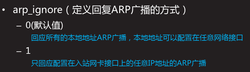
-Back end 128 server
[root@localhost network-scripts]# cat >> /etc/sysctl.conf <<EOF
> net.ipv4.conf.all.arp_ignore = 1
> net.ipv4.conf.lo.arp_ignore = 1
> net.ipv4.conf.lo.arp_announce = 2
> net.ipv4.conf.all.arp_announce = 2
> EOF

[root@localhost network-scripts]# sysctl -p
net.bridge.bridge-nf-call-ip6tables = 1
net.bridge.bridge-nf-call-iptables = 1
net.bridge.bridge-nf-call-arptables = 1
net.ipv4.ip_forward = 1
//The following 4-line configuration is newly added:
net.ipv4.conf.all.arp_ignore = 1
net.ipv4.conf.lo.arp_ignore = 1
net.ipv4.conf.lo.arp_announce = 2
net.ipv4.conf.all.arp_announce = 2

[root@localhost network-scripts]# systemctl restart NetworkManager
[root@localhost network-scripts]# systemctl restart network

-Back end 129 server
[root@test2 network-scripts]# cat >> /etc/sysctl.conf <<EOF
> net.ipv4.conf.all.arp_ignore = 1
> net.ipv4.conf.lo.arp_ignore = 1
> net.ipv4.conf.lo.arp_announce = 2
> net.ipv4.conf.all.arp_announce = 2
> EOF

[root@localhost network-scripts]# sysctl -p
net.bridge.bridge-nf-call-ip6tables = 1
net.bridge.bridge-nf-call-iptables = 1
net.bridge.bridge-nf-call-arptables = 1
net.ipv4.ip_forward = 1
net.ipv4.conf.all.arp_ignore = 1
net.ipv4.conf.lo.arp_ignore = 1
net.ipv4.conf.lo.arp_announce = 2
net.ipv4.conf.all.arp_announce = 2

[root@test2 network-scripts]# systemctl restart NetworkManager
[root@test2 network-scripts]# systemctl restart network
Meaning of the above configuration:
when an ARP broadcast asks who is 192.168.2.133 (VIP), the local computer ignores the ARP broadcast and does not make any response, and the local computer does not announce that its lo return address is 192.168.2.133
3, Deploy LVS-DR mode scheduler
1. Create a cluster scheduling server
[root@test3 ~]# yum -y install ipvsadm

[root@test3 ~]# ipvsadm -C

[root@test3 ~]# ipvsadm -A -t 192.168.2.133:80 -s wrr / / create a virtual cluster server and set the scheduling algorithm to weighted polling wrr
2. Add back-end real server
- g: parameter sets LVS working mode to DR mode
- w: set weight
[root@test3 ~]# ipvsadm -a -t 192.168.2.133:80 -r 192.168.2.128 -g -w 1

[root@test3 ~]# ipvsadm -a -t 192.168.2.133:80 -r 192.168.2.129 -g -w 2
3. View the rule list and save the rule
[root@test3 ~]# ipvsadm -Ln
IP Virtual Server version 1.2.1 (size=4096)
Prot LocalAddress:Port Scheduler Flags
  -> RemoteAddress:Port           Forward Weight ActiveConn InActConn
TCP  192.168.2.133:80 wrr
  -> 192.168.2.128:80             Route   1      0          0
  -> 192.168.2.129:80             Route   2      0          0

[root@test3 ~]# ipvsadm-save -n > /etc/sysconfig/ipvsadm-config
4, Client test
[root@VOS3000 ~]# curl  http://192.168.2.133:80
I am 192.168.2.129
[root@VOS3000 ~]# curl  http://192.168.2.133:80
I am 192.168.2.129
[root@VOS3000 ~]# curl  http://192.168.2.133:80
I am 192.168.2.128
[root@VOS3000 ~]# curl  http://192.168.2.133:80
I am 192.168.2.129
[root@VOS3000 ~]# curl  http://192.168.2.133:80
I am 192.168.2.129
[root@VOS3000 ~]# curl  http://192.168.2.133:80
I am 192.168.2.128
[root@VOS3000 ~]# curl  http://192.168.2.133:80
I am 192.168.2.129
[root@VOS3000 ~]# curl  http://192.168.2.133:80
I am 192.168.2.129
[root@VOS3000 ~]# curl  http://192.168.2.133:80
I am 192.168.2.128
[root@VOS3000 ~]# curl  http://192.168.2.133:80
I am 192.168.2.129
you can see that every time we execute a curl command (equivalent to refreshing a web page), the scheduler will poll different back-end real servers according to the weight value.
reflection
1. Why is VIP configured on all RS
because when the dispatcher forwards the request to the corresponding RS, it does not modify the destination IP of the message, so the destination IP of the request message is still VIP, so if the RS is not configured with VIP, the message will be discarded after arriving at rs.
2. Why all RS should set arp_ignore=1 and ARP_ Announcement = 2
arp_ignore=1: only respond to ARP requests whose destination IP address is the local address on the receiving network card.
because we have configured VIP on RS, there is an IP conflict at this time. When an external client sends a request to VIP, it will send the arp request first, and the dispatcher and RS will respond to the request. If an RS responds to the request, then all requests from the client will be sent to the RS without LVS, so there is no real load balancing and LVS has no significance. Therefore, we need to set RS not to respond to VIP arp requests, so that all arp requests from external clients to VIP will be resolved to the scheduler, and then sent to each RS through the scheduler of LVS.
system default arp_ignore=0, which means to respond to the arp request for the local IP address received on any network card (including the address on the loopback network card), regardless of whether the destination IP is on the receiving network card or not. In other words, if there are two network card devices A and B on the machine, even if the arp request for B IP is received on the A network card, it will respond. And arp_ If ignore is set to 1, the arp request of B IP will not be responded to. Since lo will not communicate with the outside world, if there is only one external network port, in fact, you only need to set this external network port. However, in order to ensure the security, all is also set in many cases.
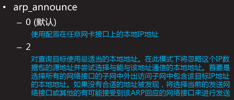
arp_ Announcement = 2: when sending ARP request, the network card uses the exit network card IP as the source IP
when RS processes the request and wants to send the response back to the client, and wants to obtain the destination MAC address corresponding to the destination IP, it needs to send the arp request. The purpose IP of arp request is to obtain the IP of MAC address. What about the source IP of arp request? It is natural to think of the source IP address of the response message, but it is not necessarily the case. The source IP of the arp request can be selected, while the arp_ The function of announcement is to control how to choose this address. System default arp_ Announcement = 0, that is, the source IP can be selected at will. This will lead to a problem. If the IP address of other network interfaces is used when sending arp request, other machines will update the MAC address of this IP when receiving the request after reaching the network, but in fact it should not be updated. Therefore, in order to avoid the confusion of arp table, we need to limit the source IP of arp request to the outlet IP, so we need to set arp_announce=2.
3. Why is VIP on RS configured on lo
it can be seen from the above that as long as the VIP on RS does not respond to the arp request, it is not necessarily configured on the lo, but also on other network interfaces. Since the lo device will not directly receive external requests, as long as the exit network card on the machine is set, it will not respond to the arp request interface on the non local network card. But if the VIP is configured on other network ports, in addition to the above configuration, you need to configure the network port not to respond to any arp request, that is, arp_ignore to be set to 8.
4. Why the VIP mask configured by lo on RS is 32 bits
this is due to the particularity of the lo device. For example, if the LO is bound to 192.168.0.200/24, the device will respond to all IP requests of the network segment (192.168.0.1-192.168.0.254), rather than only responding to the address 192.168.0.200.
5. Why should scheduler and RS be in the same network segment
according to the principle of DR mode, the scheduler only modifies the destination mac of the request message, that is, the forwarding is in the second layer, so the scheduler and RS need to be in the same network segment, so ip_forward doesn't need to be turned on either.
↓↓↓↓↓↓
Recently, I have applied for a WeChat official account. I will share some knowledge of operation and maintenance. Original public number: non famous operation and maintenance welfare: official account reply to "official account", send and transport operation and maintenance materials, and self study materials!