ESP32S2 small project, FM, network clock / radio, Arduino development environment
Effect display
@
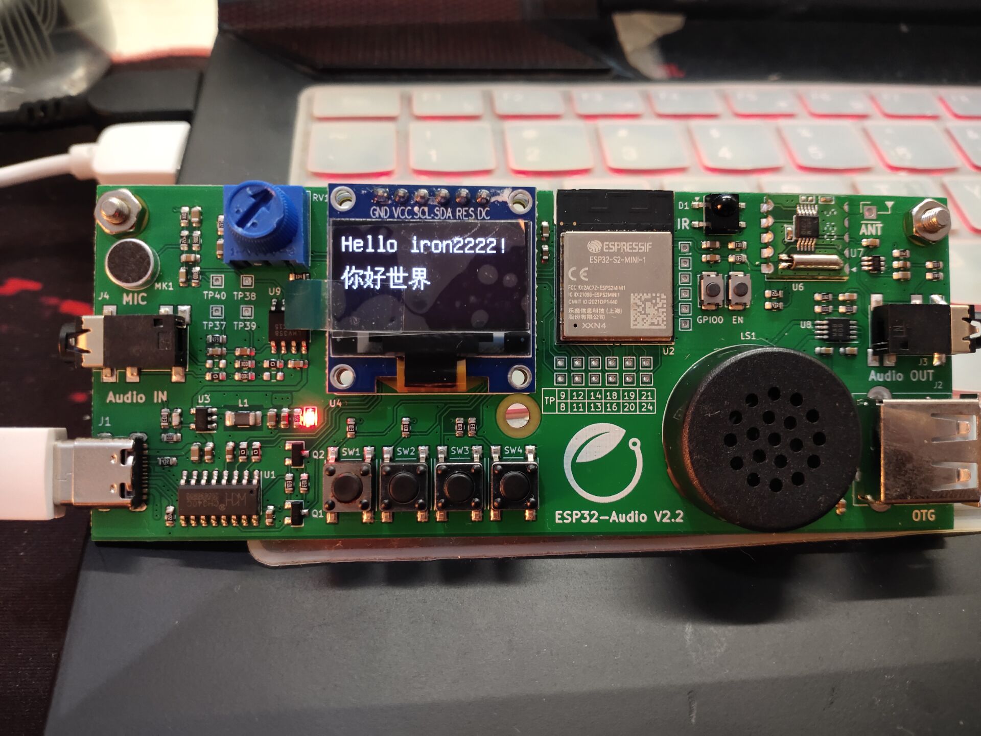
Boot animation:
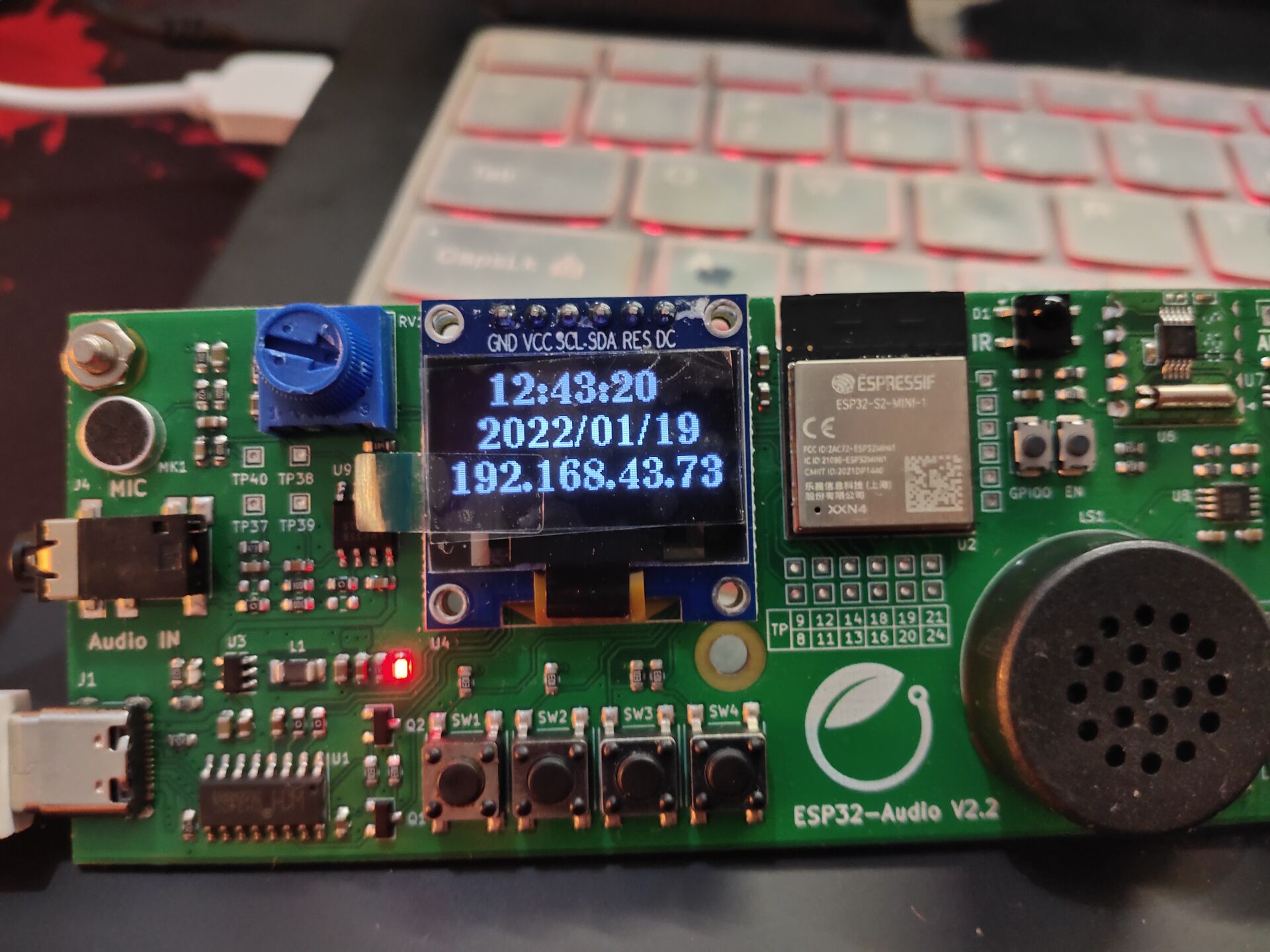
Network clock:
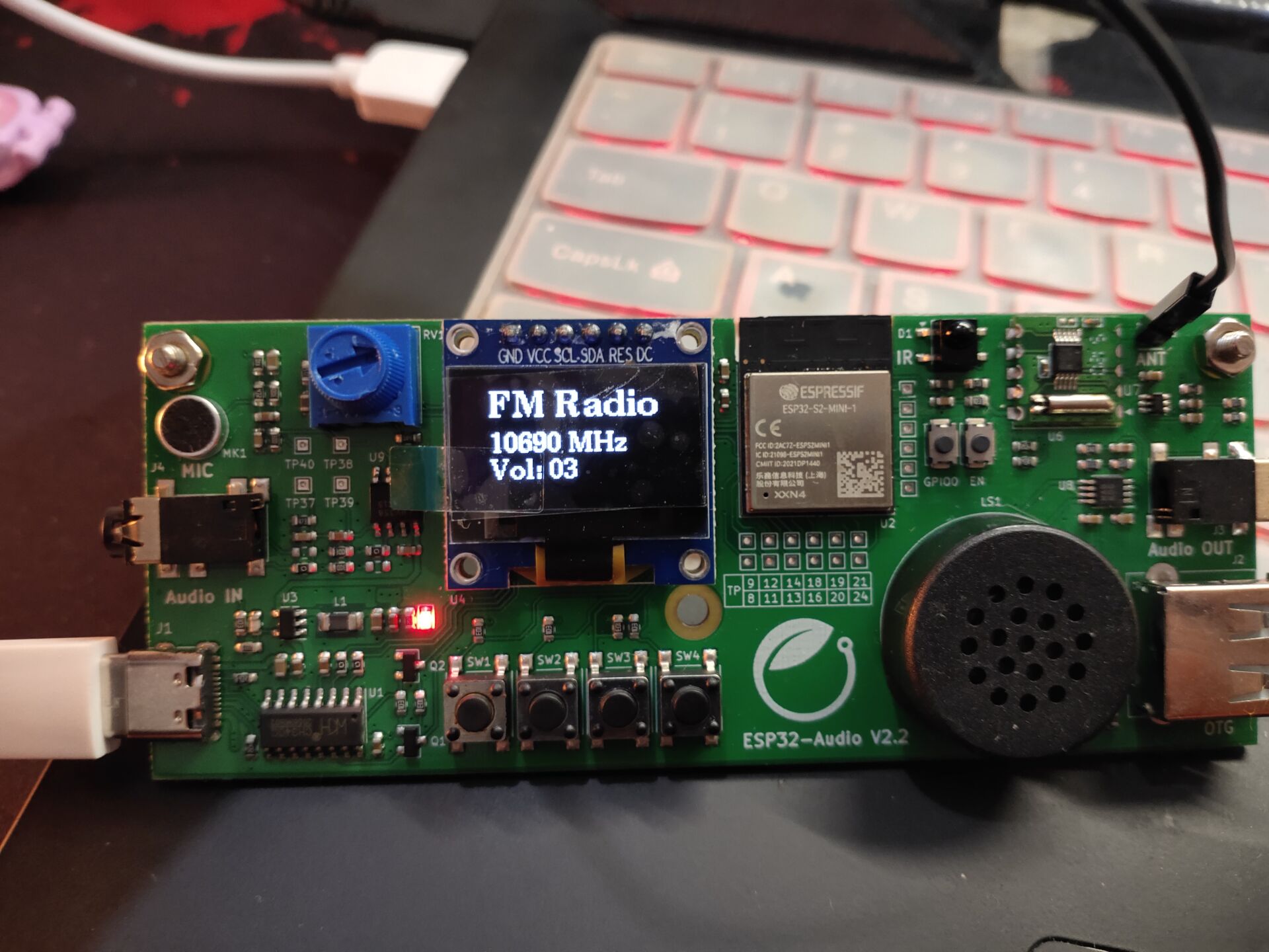
FM module:
Network radio:

hardware platform
ESP32 is a domestic WiFi chip of Lexin.
ESP32-S2-MINI-1 adopts PCB on-board antenna, the module is equipped with 4MB SPI flash, 32-bit LX7 single core processor, and the working frequency is up to 240 MHz. 43 GPIO ports, 14 capacitive sensing IO ports, support SPI, I2C, I2S, UART, ADC/DAC, PWM and other standard peripherals, support LCD interface (8-bit parallel port RGB, 8080, 6800 interface), support 8 - / 16 bit DVP image sensor interface, support the maximum clock frequency to 40 MHz, and support full speed USB OTG.
Based on ESP32-S2-MINI-1, the hard core school has expanded microphone input, key input, infrared input, FM radio module, 12864OLED screen output and speaker (headphone interface) output.
For specific information, please refer to the following website:
Electronic forest Internet of things / audio signal processing platform based on ESP32-S2 module
Development platform
The optional platforms are: ESP IDF, Arduino, and cicruitpathon. Because I just played the ESP8266 module with the Arduino platform some time ago, I choose the Arduino platform for development (I won't tell you, because the ESP IDF compilation tool chain is not configured well).
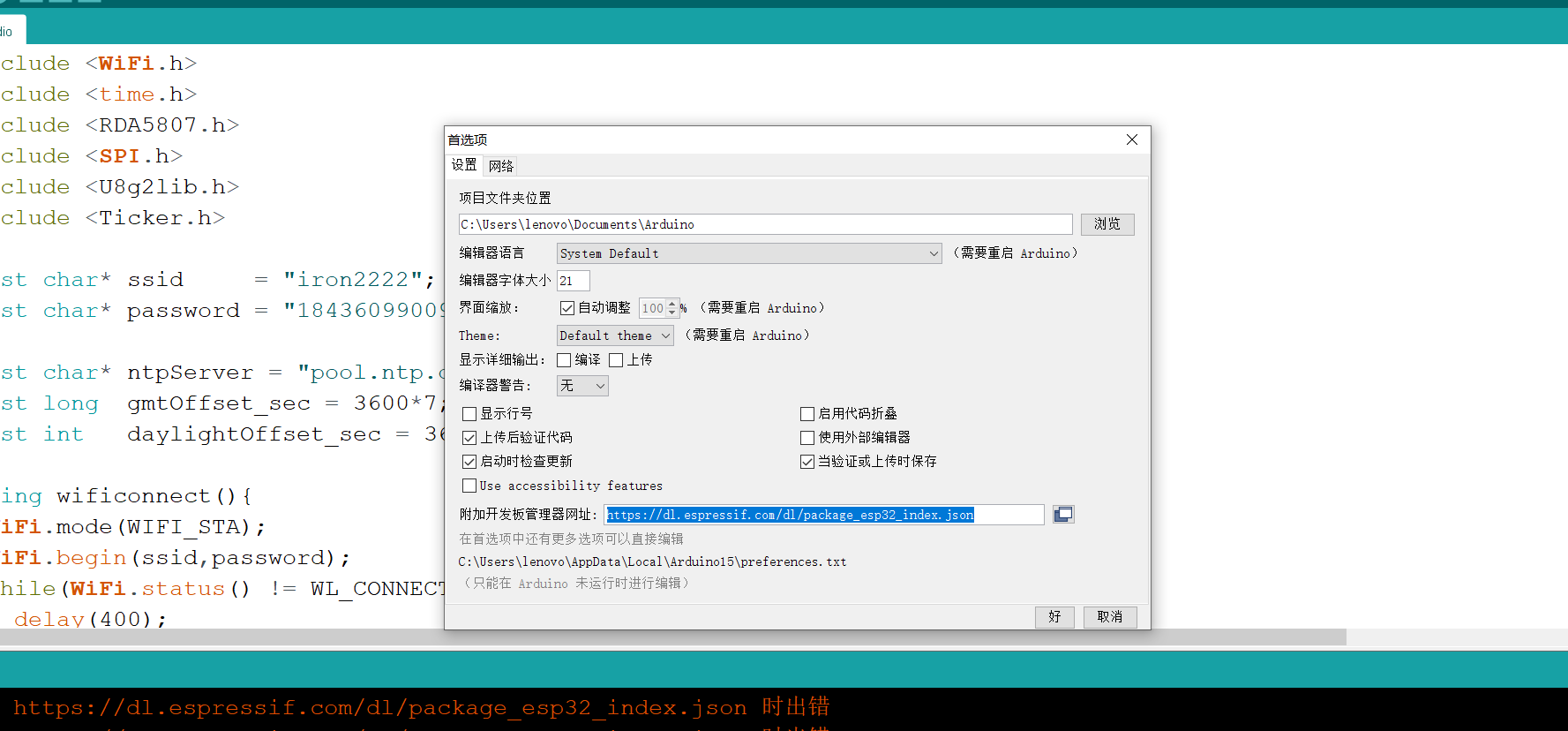
Simple environment configuration
Step 1: development board management website in preferences:
https://dl.espressif.com/dl/package_esp32_index.json
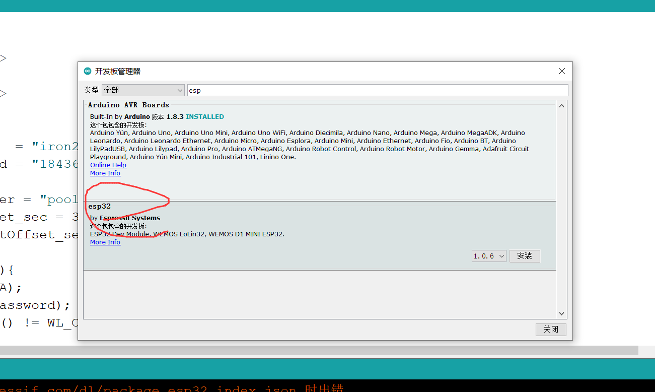
Step 2: the development board manager, find ESP32 and download it
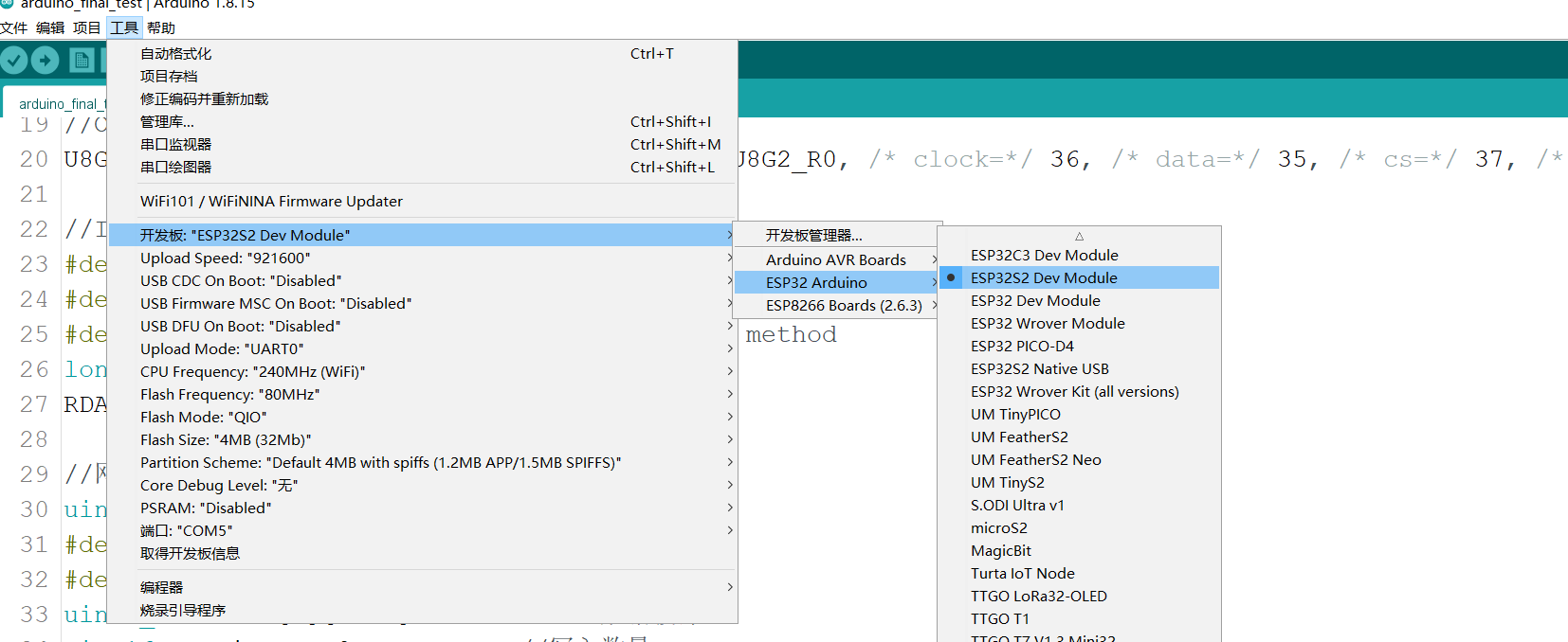
Step 3: change the development board
Because the download is too slow, I usually directly use the ESP32 package downloaded by others, but the problem is quite a lot. Let me show you my environment configuration history chart:

Manual configuration
Finally, I will tell you a method I have successfully tried:
First, download and unzip my package
--Sharing from Baidu online disk super member V4
hi, this is the content I share with Baidu online disk ~ copy this content and open the "Baidu online disk" APP to get it
Link: [external link picture transfer failed. The source station may have anti-theft chain mechanism. It is recommended to save the picture and upload it directly (img-rqh7p6cg-1643251689534)( file:///C: \Users\lenovo\AppData\Roaming\Tencent\QQTempSys[5UQ[BL(6~BS2JV6W}N6[%S.png)] https://pan.baidu.com/s/1Pcb6X0YfKsrcxr-ZpKr4wA
Extraction code: qw35
Then, unzip it into your own arduino installation path and replace it
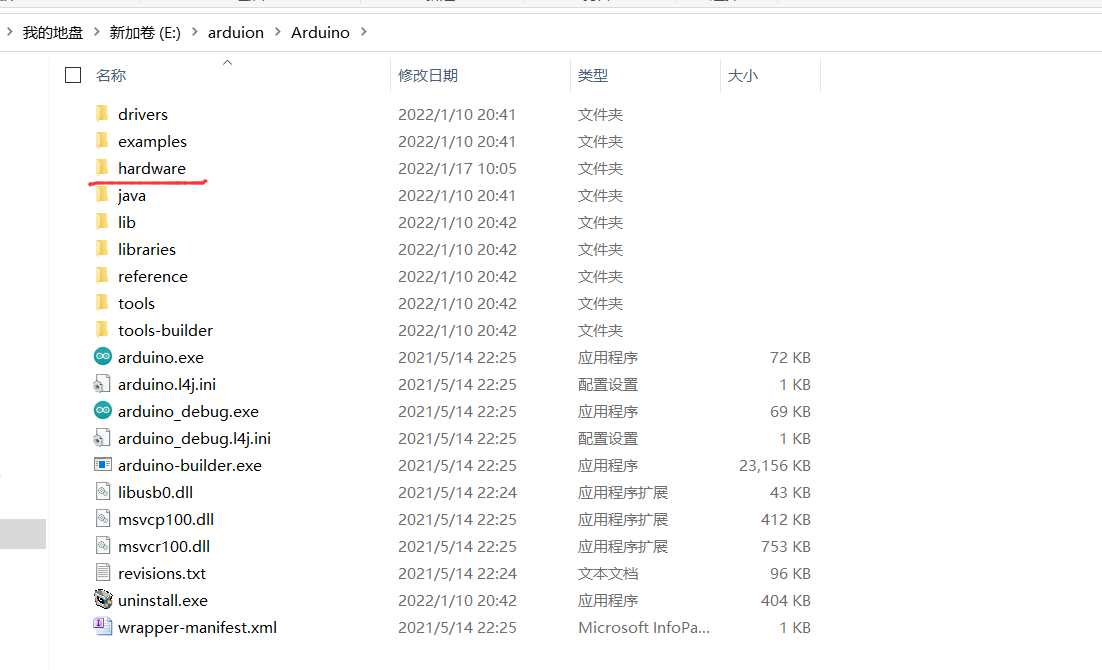
Turn it off and open Arduino again to see the development board.
In the future, if you want to configure any development board environment, just put its package in this path, and the personal test is effective.

Everything is ready. The next step is software development.
Program description
Code logic:
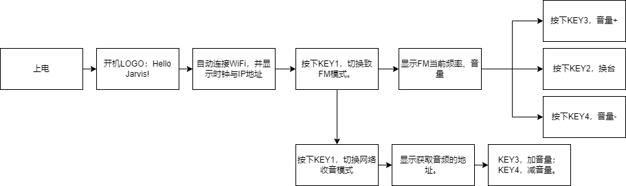
Logic is not complicated.
Connect WiFi:
//wifi user name and password
char* ssid     = "iron2222";
char* password = "*******9009";
//Start the WiFi service. Here is the client (put it in the set up function)
  WiFi.begin(ssid, password);
  Serial.print("Connecting to ");              // Serial port monitor outputs network connection information
  Serial.print(ssid); Serial.println(" ...");  // Inform the user that a WiFi connection is being attempted
  int i = 0;                                   // This program statement is used to check whether the WiFi connection is successful
  while (WiFi.status() != WL_CONNECTED) {      // WiFi. The return value of the status() function is determined by the WiFi connection status.
    delay(1000);                               // If the WiFi connection is successful, the return value is WL_CONNECTED
    Serial.print(i++); Serial.print(' ');      // Here, let nodemocu check WiFi every second through While loop Return value of status() function
  }                                            // At the same time, nodemocu will output the connection time to read seconds through the serial port monitor.
                                               // This second reading is realized by adding 1 to variable i every second.
  Serial.println("");                          // After WiFi connection is successful
  Serial.println("Connection established!");   // The "connection success" message will be output through the serial port monitor.
  Serial.print("IP address:    ");             // The IP address will also be output. This function is called
  Serial.println(WiFi.localIP());              // WiFi. Implemented by the localip () function. The return value of this function is the IP address of NodeMCU.
  ipaddress = WiFi.localIP().toString();
Network clock:
//Network clock setting
const char *ntpServer = "pool.ntp.org";
const long gmtOffset_sec = 8 * 3600;
const int daylightOffset_sec = 0;
 // Obtain and set the time from the network time server. After successful acquisition, the chip will use the RTC clock to keep the time updated (put it in the set up function)
  configTime(gmtOffset_sec, daylightOffset_sec, ntpServer);
  printLocalTime();
//Network clock display function
void timer_show() {
  struct tm timeinfo;
  if (!getLocalTime(&timeinfo))
    {
        u8g2.clearBuffer();
        u8g2.setFontDirection(0);
        u8g2.setFont(u8g2_font_ncenB08_tr);
        u8g2.setCursor(0, 40);
        u8g2.print("Failed to obtain time");
        u8g2.setCursor(2,55);
        u8g2.print(ipaddress);
        u8g2.sendBuffer();
        return;
    }
  u8g2.clearBuffer();
  u8g2.setFontDirection(0);
  u8g2.setFont(u8g2_font_ncenB14_tr);
  u8g2.setCursor(20, 15);
  u8g2.print(&timeinfo, "%H:%M:%S");
  u8g2.setCursor(15, 35);
  u8g2.print(&timeinfo, "%Y/%m/%d");
  u8g2.setCursor(2,55);
  u8g2.print(ipaddress);
  u8g2.sendBuffer();
}
FM radio:
Because the FM module transmits data through I2C, open the corresponding configuration.
//I2C pin setting
#define ESP32_I2C_SDA 5
#define ESP32_I2C_SCL 4
#define MAX_DELAY_RDS 40   // 40ms - polling method
long rds_elapsed = millis();
RDA5807 rx;
 // I2C related settings (put in the set up function)
  Wire.begin(ESP32_I2C_SDA, ESP32_I2C_SCL);
  rx.setup();
  rx.setVolume(0);//Volume setting, adjustable
  delay(500);
  //FM related settings
  rx.setFrequency(10650); //On frequency, adjustable
  //Enable SDR
  rx.setRDS(true);
//FM mode display function
void FM_show() {
  char str[64] = {0};
  u8g2.firstPage();
  u8g2.clearBuffer();         //Clear internal buffer
  u8g2.setFontDirection(0);   //Set font orientation

  u8g2.setFont(u8g2_font_ncenB14_tr);     //Set font
  u8g2.setCursor(15, 20);
  u8g2.print("FM Radio");

  u8g2.setFont(u8g2_font_ncenB10_tf);
  u8g2.setCursor(15, 40);
  sprintf(str, "%u MHz",rx.getFrequency() );
  u8g2.print(str);
  u8g2.setCursor(15, 55);
  sprintf(str, "Vol: %2.2u",rx.getVolume());
  u8g2.print(str);

  u8g2.sendBuffer();
  delay(1000);
}
Network radio:
In fact, we can focus on it here, because it involves DAC. About what ADC/DAC is, you can read this blog post:
Blog Garden: https://www.cnblogs.com/iron2222/p/15833426.html
CSDN: https://iron2222.blog.csdn.net/article/details/122636386?spm=1001.2014.3001.5502
The whole implementation process of webradio can be divided into three parts:
- Get the audio stream. The program uses the http protocol to get the audio data from a server and store the whole data in a buffer.
- Decode the audio stream. When there is certain data in the buffer (which can be adjusted through macros), start the decoding thread. The decoding thread will extract the data from the buffer, then call the decoder library and decode the audio stream into a digital signal that can be directly output.
- The decoded data is output through the DAC. After each frame of data is decoded by the decoding thread, it is directly sent to the DAC through the I2C driver.
There is a synchronization problem, that is, the synchronization between obtaining the audio stream from the server and decoding the audio stream. If the obtained audio flows fast and exceeds the decoding speed, it may burst the buffer, so some data will be lost; If the decoding speed is too fast and exceeds the speed of obtaining audio, it may consume the buffer cleanly, and the sound jam problem will also occur. This requires trade-offs.
However, the decoding of online audio stream cannot be realized in S2, so an independent network audio library is built by using ESP8266 as the network server and socket TCP transmission. The black module seen above.

//Network radio
uint16_t num=0;
#define WEBSERVERIP "192.168.43.212"
#define WEBSERVERPORT 3999
uint8_t netbuf[3][1024];      //Network data buffer
uint16_t writep = 0;          //Number of writes
uint16_t readp = 0;           //Number of reads
WiFiClient client;            //Declare a client object to connect to the server
bool connstat = false;        //Connection status
bool iswaitecho = false;      //Wait for server response
Ticker flipper;               //Time interruption
uint16_t m_offset = 0;

void onTimer(void) {
  if(readp<=writep)  dacWrite(17, netbuf[readp % 3][m_offset++]);      //Play a sound
  if (m_offset >= 1024) {
    m_offset = 0;
    readp++;      //Read complete a buffer
  }
}
bool connNetMusic() {
  uint8_t i = 0;
  while (i < 5) { //Up to 5 connections
    if (client.connect(WEBSERVERIP, WEBSERVERPORT)) {
      connstat = true;
      Serial.println("Connection successful");
      return true;
    } else {
      Serial.println("Access failed");
      client.stop(); //Close client
    }
    i++;
    delay(100);
  }
  return false;
}

void playMusic() {
        digitalWrite(41, HIGH);digitalWrite(42, HIGH);
        if (connstat == true){

            if (iswaitecho == false && (writep - readp) < 2) {
                client.write('n');          //Apply for a buffer
                iswaitecho = true;
            }
            if (client.available()) { //If there is data to read
                num = client.read(netbuf[writep % 3], 1024);
                if (writep == 0 && readp == 0) {
                    flipper.attach(0, onTimer);     //When the timer interrupt is turned on, it means 20000 interrupts per second
                }
                writep++;
                iswaitecho = false;
            }
        }
}
The above is the configuration of each module of the code. The complete code can be downloaded from my gitee library. The final program folder name is arduino_final_test, other folders are my functional tests of various modules. Everyone can play with them and complete the project step by step.
Code cloud: https://gitee.com/iron2222/esp32
epilogue
There are still many areas that can be improved in this project, such as FM's automatic channel search function, and the connection of network radio stations.
In the next step, I will use the newly built ESP IDF platform for redevelopment. Some of the arduino platform is not so handy. I wish me fewer bug s!!!

I wish you all a happy holiday and Spring Festival!