In the process of using the library of lighting technology to control LED, we briefly mentioned the overall process of MQTT. Because its MQTT server is provided by lighting technology, we don't know a lot of connection details. In this section, we are going to build a local MQTT server, and then use MQTT to control LED Client sends control command to MQTT server to control our LED.
First of all, we need to start the MQTT server. We don't need to talk about the startup mode. The previous chapter has explained that after the startup, the connection address is 192.168.43.2:1883. Remember that the connection address can't be written as 127.0.0.1, otherwise the connection can't be successful.
Then, the coding operation is started. The specific coding contents are as follows:
#include <ESP8266WiFi.h>
#include <PubSubClient.h>

#define JDQ 16

const char* MQTT_SERVER  = "192.168.43.2";
const int   MQTT_PORT    = 1883;
const char* MQTT_USRNAME = "addmin";
const char* MQTT_PASSWD  = "public";
const char* TOPIC = "home/devices/onoff/";
const char* CLIENT_ID    = "scy-mqtt-client";  //Current device's clientid sign

const char* ssid     = "cxsr";     //To be connected WIFI
const char* password = "scy251147";//To be connected WIFI Password

WiFiClient espClient;
PubSubClient  client(espClient);
long lastMsg = 0;

/**
* Connect wifi
*/
void setupWifi(){
  delay(100);
  Serial.println("Startup");
  pinMode(JDQ, OUTPUT);
  WiFi.mode(WIFI_STA);//Set mode to STA
  WiFi.begin(ssid, password);

  while (WiFi.status() != WL_CONNECTED) {//wait for WiFi Connection successful
    delay(500);
    Serial.print(".");
  }

  Serial.println("");
  Serial.println("WiFi connected");
  Serial.println("IP address: ");
  Serial.println(WiFi.localIP());
}

void reconnect() {
  while (!client.connected()) {
    Serial.print("Attempting MQTT connection...");
    // Attempt to connect
    if (client.connect(CLIENT_ID)) {
      Serial.println("connected");
      // Subscribe to topics when connection is successful
      client.subscribe(TOPIC);
    } else {
      Serial.print("failed, rc=");
      Serial.print(client.state());
      Serial.println(" try again in 5 seconds");
      // Wait 5 seconds before retrying
      delay(5000);
    }
  }
}

void callback(char* topic, byte* payload, unsigned int length) {
  Serial.print("Message arrived [");
  Serial.print(topic);   // Print subject information
  Serial.print("] ");
  for (int i = 0; i < length; i++) {
    Serial.print((char)payload[i]); // Print subject content
  }
  if ((char)payload[0] == '1') {
    digitalWrite(JDQ, HIGH);   // Lighting
    Serial.print(" turn on the light");
  } else {
    digitalWrite(JDQ, LOW);   // Lights out
    Serial.print(" Turn off the lights");
  }

  Serial.println();
}

void setup() {
  Serial.begin(115200);
  pinMode(JDQ, OUTPUT);
  setupWifi();
  client.setServer(MQTT_SERVER, MQTT_PORT); //Set up MQTT Server and port used, 1883 is the default MQTT port
  client.setCallback(callback);        //Set callback mode when ESP8266 This method is called when a subscription message is received
}

void loop() {
  if (!client.connected()) {
    reconnect();
  }
  client.loop();
}
It should be noted that in the process of execution, the networking operation will be carried out first, and then the operation of connecting to the MQTT server will be carried out. After these two operations are completed, we can control them through the MQTT Client.
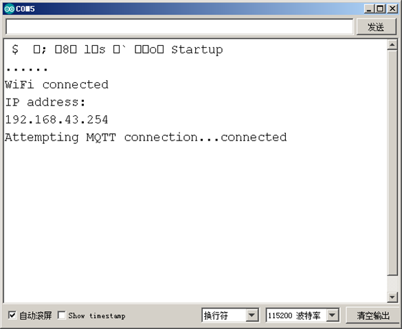
After the code is burned, we can see the specific connection through the serial port debugging window:
After that, we open the local MQTT Client and connect to the home/devices/onoff / theme. After the connection is successful, we send the control code:
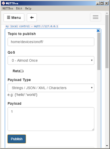
Here I send 1, which means to turn on the relay, i.e. to turn on the light. You can see that the light is turned on by us:

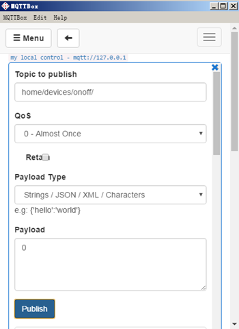
When sending 0, it means that the relay is off, and the light is off, as shown in the figure:

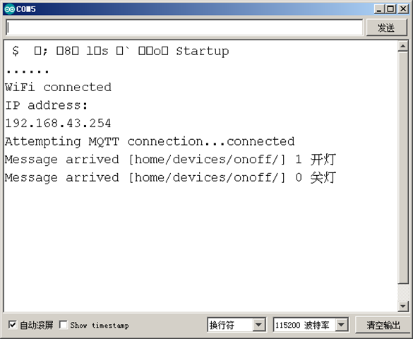
At this time, on our serial port monitor, you can see the printed log as follows:
Is it easy to use?