OSG Quick Start Guide Download address
1, Geometry overview
osg::ref_ptr<osg::Node> createSceneGraph()
{
 // Create an object to hold geometric information
 osg::ref_ptr<osg::Geometry> geom = new osg::Geometry;

 // Creates an array of four vertices
 osg::ref_ptr<osg::Vec3Array> v = new osg::Vec3Array;
 geom->setVertexArray( v.get() );
 v->push_back( osg::Vec3( -1.f, 0.f, -1.f ) );
 v->push_back( osg::Vec3( 1.f, 0.f, -1.f ) );
 v->push_back( osg::Vec3( 1.f, 0.f, 1.f ) );
 v->push_back( osg::Vec3( -1.f, 0.f, 1.f ) );

 // Create an array of four colors
 osg::ref_ptr<osg::Vec4Array> c = new osg::Vec4Array;
 geom->setColorArray( c.get() );
 geom->setColorBinding( osg::Geometry::BIND_PER_VERTEX );
 c->push_back( osg::Vec4( 1.f, 0.f, 0.f, 1.f ) );
 c->push_back( osg::Vec4( 0.f, 1.f, 0.f, 1.f ) );
 c->push_back( osg::Vec4( 0.f, 0.f, 1.f, 1.f ) );
 c->push_back( osg::Vec4( 1.f, 1.f, 1.f, 1.f ) );

 // Creates an array of unique normals
 osg::ref_ptr<osg::Vec3Array> n = new osg::Vec3Array;
 geom->setNormalArray( n.get() );

 geom->setNormalBinding( osg::Geometry::BIND_OVERALL );
 n->push_back( osg::Vec3( 0.f, -1.f, 0.f ) );

 // Draws a polygon with four vertices from the saved data
 geom->addPrimitiveSet(
 new osg::DrawArrays( osg::PrimitiveSet::QUADS, 0, 4 ) );

 // Add geometry (Drawable) to the Geode class and return Geode
 osg::ref_ptr<osg::Geode> geode = new osg::Geode;
 geode->addDrawable( geom.get() );
 return geode.get();
}
1. Operation method
- Creates an array of vertices, colors, and normals
- Create osg::Geometry, a. put vertices, colors and normals into geometry, B. OSG:: drawarrays to specify the drawing method
- osg::Geode scene instantiation, geometric information into the node
2. Vector and array classes
| class | explain | purpose |
|---|---|---|
| osg::Vec2 | Two dimensional floating point array | 2D texture |
| osg::Vec3 | 3D floating point array | Vertex and normal data |
| The following is the STD:: vector < > version | — | — |
| osg::Vec2Array | Array of vec2 | Texture coordinate array |
| osg::Vec3Array | Array of vec3 | vertex array |
| osg::Vec4Array | Array of vec4 | Color array |
Tip: the use of vector resize() operator [] can reduce the reallocation of memory
3.Drawable class - Geometry
- Used to save rendering data
- Drawable is a virtual base class that cannot be instantiated directly
Drawable subclass
- Geometry
| Geometry function | OpenGL corresponding function | explain |
|---|---|---|
| Set VBO data (equivalent to) | — | — |
| setVertexArray | glVertextPointer() | To put it bluntly, it is the core VAO+VBO |
| setColorArray | glColorPointer() | Save color |
| setNormalArray | glNormalPointer() | Save vector |
| branch | Specifies whether other variables and vertices are on the same line | — |
| setColorBinding | setColorBinding(osg::Geometry::BIND_PER_VERTEX) | Equivalent to in Core mode, in one line |
| setNormalBinding | setColorBinding(osg::Geometry::OVERALL) | It is equivalent to that in Core mode, there are in each line |
| painting | — | — |
| addPrimitiveSet() | addPrimitiveSet( new osg::DrawArrays( osg::PrimitiveSet::QUADS, 0, 4 ) ); | Set rendering mode |
- addPrimitiveSet(osg::PrimitiveSet *) and osg::DrawArrays
geom->addPrimitiveSet( new osg::DrawArrays( osg::PrimitiveSet::QUADS, 0, 4 ) );
Explanation:
addPrimitiveSet(↓)
a. osg::DrawArrays (QUADS) – draw squares in order
b. osg::DrawElementsUByte (QUADS) – draw squares in the specified order
c. osg::DrawElementsUByte (POINTS) – draw POINTS in the specified order
This is the most important sentence - painting
4.PrimitiveSet class diagram
| type | ||
|---|---|---|
| DrawArrays | Draw in order | DrawArrays(mode) |
| DrawElementsUInt | Draw according to the specified points |
DrawArrays mode type
| OSG | GL |
|---|---|
| osg::PrimitiveSet::POINTS | GL_POINT |
| osg::PrimitiveSet::LINES | GL_LINES |
2, Leaf node (Geode)
- A leaf node (Geode) no longer has children
- Save Geometry for rendering
- Geode::addDrawable(Drawable–Geometry)
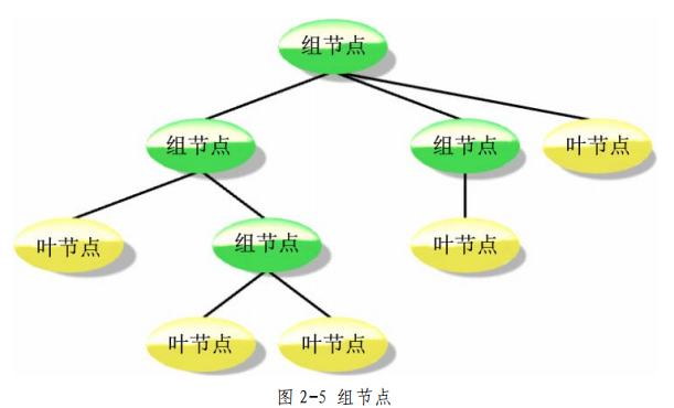
3, Group node (osg::Group)
Summary: Group defines the interface for child nodes, and all nodes derived from group support child nodes (Geode is an exception, he has no group attribute)
1 sub interface – from osg::Group
Internal data: STD:: vector < ref_ ptr > child
class Group:public Node
{
	//internal data
	std::vector< ref_ptr<Node> > child;
	//Add, delete, modify and check
	bool addChild(Node*);
	bool removeChild(Node*);
	bool replaceChild(Node*);
	bool containChild(Node*);
	//number
	unsigned int getNumChildren();
}
2 parent interface – from osg::Node
Internal list: STD:: vector < group * > parentlist;
Because it's just a reference, there's no need to manage the destructor, all of which are ordinary pointers
class Node: public Object
{
	//Define type
	typedef std::vector<Group*> ParentList;

	//query
	ParentList& getParents();
	Group* getParent(unsigned int I);

}
contrast
| type | Parent interface - from Node | Sub interface - from Group |
|---|---|---|
| storage | std::vector<Group*> ParentList ParentList parents | std::vector< ref_ptr<Node> > child |
| increase Delete change | nothing | bool addChild(Node*); bool removeChild(Node*); bool replaceChild(Node*); |
| check | bool containChild(Node*) | ParentList& getParents(); Group* getParent(unsigned int I); |
typedef std::vector<Group*> ParentList;
a. The child node does not need to manage the memory of the parent node, but directly saves the ordinary pointer, because only the parent node can release the child node
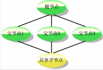
b. The child node holds multiple parent nodes
c. This pointer is automatically cleared
d. Usually: a node has a parent node (getNumParents() = = 0), get getParent(0)
3. Transform node
| Matrx+Transform | Matrix | |
|---|---|---|
| Class name | osg::Transform osg:: MatrixTransform osg::PositionAttitudeTransform | osg::Matrix |
| function | Nodes: recording all transforms | Matrix - calculation tool |
3.1 Matrix calculation tool
osg::Matrix = 4 × 4 matrix
Matrix itself is a 4 × 4 matrices (16 float s) are used for pure calculation
- Matrix assignment
osg::Matrix m;
m(0,1) = 0.f;  //Row 0, column 1
m(1,2)= 0.f;   //Row 1, column 2
- vector × Matrix matrix × matrix
osg::Matrix T;
T.makeTranslate(x,y,z);

osg:Matrix R;
R.makeRotate(angle,axis);

Vec3 vPrime= v*R*T;
Comparison of matrix multiplication between OSG and OpenGL
| OSG | OpenGL |
|---|---|
| Left multiplication | Right multiplication |
| v2= v1×R×T; | v2 = T×R×v1 |
| OSG right multiply | Multiply according to mathematics |
- The right multiplication of matrix leads to the change of node connection mode
| Illustration | explain |
|---|---|
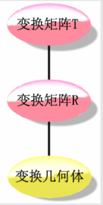 | First, a MatrixTransform of mobile MT is created to generate mobile nodes Then, create a rotating MR MatrixTransform, generate a rotating node, and hang this node under the mobile node Finally, hang Geode under the rotation node |
3.2 matrix transform node
| Class name | type | explain | |
|---|---|---|---|
| MatrixTransform | node | Reference - natural support ref_ ptr<> | Just to catch the matrix |
| Matrix | computing equipment | Ordinary class, does not support smart pointer | Just to calculate |
osg::ref_ptr<osg::MatrixTransform> mt = new osg::MatrixTransform;
osg::Matrix m;
m.setTtranslate(x,y,z);
mt->setMatrix(m);
Matrix::set function, passed in by column;
osg::Matrix m;
m.set( 1.f, 0.f, 0.f, 0.f,
 0.f, 1.f, 0.f, 0.f,
 0.f, 0.f, 1.f, 0.f,
 10.f, 0.f, 0.f, 1.f );

osg::ref_ptr<osg::MatrixTransform> mt = new osg::MatrixTransform;
mt.setMatrix(m);
3.3 position attribute transformation node
Guess:
| MatrixTransform | PositionAttitudeTransform |
|---|---|
| Matrix matrix in AutoCAD | This is the way of yaw pitch roll in Bentley |
-
Quaternion osg::Quat
How many degrees? About which axis -
Around an axis
OSG:: quat Q0 (radian, axis);
Float angle(M_PI*0.5f);
osg::Vec3 axis(0.7f,0.7f,0.f);//Inclined axis

osg::Quat q0(angle,axis);
- Go around yaw pitch roll
OSG:: quat Q0 (radian yaw, radian pitch, radian roll, axis yaw, axis pitch, axis roll);
osg::Vec3 yawAxis(0.f,0.f,1.f);
osg::Vec3 pitchAxis(1.f,0.f,0.f);
osg::Vec3 rollAxis(0.f,1.f,0.f);

osg::Quat q1(yawRad,yawAxis,pitchRad,pitchAxis,rollRad,rollAxis);
IV LOD level of detail node
- LOD can add child nodes
-
LOD can control the display of child nodes
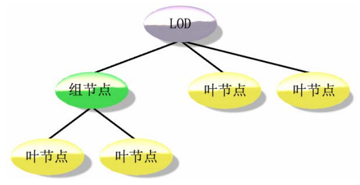
Explanation:
Above: LOD has three child nodes, which are displayed only when the distance between observation points meets the effective range of the first child node -
code
osg::ref_ptr<osg::Geode> geode1;
osg::ref_ptr<osg::Geode> geode2;

osg::ref_ptr<osg::LOD> lod = new osg::LOD;
lod->addChild(geode1.get(),0.f,1000.f);
lod->addChild(geode2.get(),950.f,1200.f);
Explanation:
a. Displayed when the distance between the viewpoint and this child node is less than 1000 units
b.LOD is a range that can be specified for each child node
Five switch nodes (osg::Switch)
osg::ref_ptr<osg::Switch> sw= new osg::Switch;

sw->addChild(group0.get(),true);
sw->addChild(group1.get(),false);
sw->addChild(geode.get(),false);