preface
This paper teaches you to use the external interrupt, connect the key to the IO port, and use the interrupt to control the internal program of the single chip microcomputer.
Equipment used: STM32F407
1, Introduction to STM32F4 external interrupt
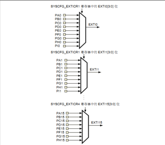
Each io of STM32F4 can be used as an interrupt input port for external interrupt. STM32 designs GPIO pin gpiox 0~GPIOx. 15 (x = a, B, C, D, e, F,G,H,I) correspond to interrupt lines 0 ~ 15 respectively. In this way, each interrupt line corresponds to up to 9 IO ports. Take line 0 as an example: it corresponds to gpioa 0,GPIOB.0,GPIOC.0,GPIOD.0,GPIOE.0,GPIOF.0,GPIOG.0,GPIOH.0,GPIOI.0 The medium break line can only be connected to one IO port at a time, so it is necessary to determine which GPIO the corresponding interrupt line is configured to through configuration.
Mapping relationship between GPIO and interrupt line:
2, Programming points
- Enable the clock of IO port and initialize IO port as input;
- Configure NVIC;
- Configure key GPIO as input mode;
- Connect the key GPIO to the exi source input;
- Configure the button EXTI interrupt / event line;
- Write EXTI interrupt service function.
Related macros are defined as follows
#define KEY1_INT_GPIO_PORT 				GPIOC
#define KEY1_INT_GPIO_CLK 				RCC_AHB1Periph_GPIOC
#define KEY1_INT_GPIO_PIN 				GPIO_Pin_9
#define KEY1_INT_EXTI_PORTSOURCE 		EXTI_PortSourceGPIOC
#define KEY1_INT_EXTI_PINSOURCE 		EXTI_PinSource9
#define KEY1_INT_EXTI_LINE 				EXTI_Line9

#define KEY_INT_EXTI_IRQ  				 EXTI9_5_IRQn 		// IO ports of 5 ~ 9 are shared
#define KEY_IRQHandler 					EXTI9_5_IRQHandler
1. Enable the IO port clock and initialize the IO port as an input
First, we need to use the IO port as the interrupt input, so we need to enable the corresponding IO port clock and initialize the phase
The IO port shall be input mode
	GPIO_InitTypeDef GPIO_InitStructure;

	RCC_AHB1PeriphClockCmd(KEY1_INT_GPIO_CLK,ENABLE);	//Turn on the corresponding GPIO clock
	GPIO_InitStructure.GPIO_Pin = KEY1_INT_GPIO_PIN;	//Select pin
	GPIO_InitStructure.GPIO_Mode = GPIO_Mode_IN;		//Configure as input mode
	GPIO_InitStructure.GPIO_PuPd = GPIO_PuPd_UP;		//Configured as pull-up mode
	GPIO_Init(KEY1_INT_GPIO_PORT,&GPIO_InitStructure);	//Initialize structure
2. Turn on SYSCFG clock and set the mapping relationship between IO port and interrupt line.
1. To configure the mapping relationship between GPIO and interrupt line, we first need to turn on the SYSCFG clock. You must note here that as long as we use external interrupts, we must turn on the SYSCFG clock.
2. We configure the mapping relationship between GPIO and interrupt line. In the library function, configure the mapping relationship between GPIO and interrupt line syscfg_ Implemented by exilineconfig():
	RCC_APB2PeriphClockCmd(RCC_APB2Periph_SYSCFG, ENABLE);
	SYSCFG_EXTILineConfig(KEY1_INT_EXTI_PORTSOURCE,KEY1_INT_EXTI_PINSOURCE);
3. Initialize online interrupt, set trigger conditions, etc.
	/* Connect EXTI interrupt source to key1 pin */
  SYSCFG_EXTILineConfig(KEY1_INT_EXTI_PORTSOURCE,KEY1_INT_EXTI_PINSOURCE);

  /* Select EXTI interrupt source */
  EXTI_InitStructure.EXTI_Line = KEY1_INT_EXTI_LINE;
  /* Interrupt mode */
  EXTI_InitStructure.EXTI_Mode = EXTI_Mode_Interrupt;
  /* Falling edge trigger */
  EXTI_InitStructure.EXTI_Trigger = EXTI_Trigger_Falling;
  /* Enable interrupt / event line */
  EXTI_InitStructure.EXTI_LineCmd = ENABLE;
  EXTI_Init(&EXTI_InitStructure);
4. Configure interrupt packet (NVIC) and enable interrupts.
static void NVIC_Configuration(void)
{
  NVIC_InitTypeDef NVIC_InitStructure;

  /* Configure NVIC as priority group 1 */
  NVIC_PriorityGroupConfig(NVIC_PriorityGroup_1);

  /* Configure interrupt source: press key 1 */
  NVIC_InitStructure.NVIC_IRQChannel = KEY_INT_EXTI_IRQ;
  /* Configure preemption priority: 1 */
  NVIC_InitStructure.NVIC_IRQChannelPreemptionPriority = 1;
  /* Configure sub priority: 1 */
  NVIC_InitStructure.NVIC_IRQChannelSubPriority = 1;
  /* Enable interrupt channel */
  NVIC_InitStructure.NVIC_IRQChannelCmd = ENABLE;
  NVIC_Init(&NVIC_InitStructure);
}
5. Write an interrupt service function.
After we configure the interrupt priority, the next thing to do is to write the interrupt service function. The name of the interrupt service function is
Defined in advance in MDK. It should be noted here that there are only 7 external interrupt functions of the IO port of STM32F4, with a score of
Do not:
EXPORT EXTI0_IRQHandler
EXPORT EXTI1_IRQHandler
EXPORT EXTI2_IRQHandler
EXPORT EXTI3_IRQHandler
EXPORT EXTI4_IRQHandler
EXPORT EXTI9_5_IRQHandler
EXPORT EXTI15_10_IRQHandler
Interrupt lines 0-4 each interrupt line corresponds to an interrupt function, and interrupt lines 5-9 share the interrupt function EXTI9_5_IRQHandler, medium
Disconnection 10-15 common interrupt function EXTI15_10_IRQHandler. When writing an interrupt service function, you often use two methods
A function.
The first function is to judge whether an interrupt on an interrupt line occurs (whether the flag bit is set):
ITStatus EXTI_GetITStatus(uint32_t EXTI_Line);
This function is generally used at the beginning of the interrupt service function to determine whether an interrupt occurs. Another function is to clear a break line
Interrupt flag bit:
void EXTI_ClearITPendingBit(uint32_t EXTI_Line);
This function is generally used to clear the interrupt flag before the end of the interrupt service function.
The commonly used interrupt service function format is
void EXTI3_IRQHandler(void)
{
	if(EXTI_GetITStatus(EXTI_Line3)!=RESET)//Judge whether an interruption on a line occurs
	{ ...Interrupt logic
	EXTI_ClearITPendingBit(EXTI_Line3); //Clear the interrupt flag bit on LINE
	}
}
It should be noted here that the firmware library also provides two functions to judge the external interrupt status and clear the external status:
Function exti of flag bit_ Getflagstatus and EXTI_ClearFlag, their functions are similar to those of the previous two functions.
Just at exti_ In the getitstatus function, you will first judge whether this interrupt is enabled. Only when it is enabled can you judge the interrupt flag bit, and
EXTI_GetFlagStatus is directly used to determine the status flag bit.
6. Initialize the key configuration in the main function
We must remember to call these initialization functions in the main function. Many novice white is an old one who forgot about this (I). After the burning program, the key didn't respond. After looking at the code for a long time, I couldn't understand where the configuration was wrong.
summary
1) Enable the IO port clock and initialize the IO port as an input.
2) Enable SYSCFG clock and set the mapping relationship between IO port and interrupt line.
3) Initialize online interrupt, set trigger conditions, etc.
4) Configure interrupt packet (NVIC) and enable interrupts.
5) Write an interrupt service function.
6) Initialize the key configuration in the main function
Through the above steps, we can use external interrupts normally.